US4360248A - Multiport optical communication system and optical star structure therefor - Google Patents
Multiport optical communication system and optical star structure thereforDownload PDFInfo
- Publication number
- US4360248A US4360248AUS06/233,754US23375481AUS4360248AUS 4360248 AUS4360248 AUS 4360248AUS 23375481 AUS23375481 AUS 23375481AUS 4360248 AUS4360248 AUS 4360248A
- Authority
- US
- United States
- Prior art keywords
- fibers
- optical
- cladding
- star
- arms
- Prior art date
- Legal status (The legal status is an assumption and is not a legal conclusion. Google has not performed a legal analysis and makes no representation as to the accuracy of the status listed.)
- Expired - Lifetime
Links
Images
Classifications
- G—PHYSICS
- G02—OPTICS
- G02B—OPTICAL ELEMENTS, SYSTEMS OR APPARATUS
- G02B6/00—Light guides; Structural details of arrangements comprising light guides and other optical elements, e.g. couplings
- G02B6/24—Coupling light guides
- G02B6/26—Optical coupling means
- G02B6/28—Optical coupling means having data bus means, i.e. plural waveguides interconnected and providing an inherently bidirectional system by mixing and splitting signals
- G02B6/2804—Optical coupling means having data bus means, i.e. plural waveguides interconnected and providing an inherently bidirectional system by mixing and splitting signals forming multipart couplers without wavelength selective elements, e.g. "T" couplers, star couplers
- G02B6/2808—Optical coupling means having data bus means, i.e. plural waveguides interconnected and providing an inherently bidirectional system by mixing and splitting signals forming multipart couplers without wavelength selective elements, e.g. "T" couplers, star couplers using a mixing element which evenly distributes an input signal over a number of outputs
- G—PHYSICS
- G02—OPTICS
- G02B—OPTICAL ELEMENTS, SYSTEMS OR APPARATUS
- G02B6/00—Light guides; Structural details of arrangements comprising light guides and other optical elements, e.g. couplings
- G02B6/24—Coupling light guides
- G02B6/26—Optical coupling means
- G02B6/28—Optical coupling means having data bus means, i.e. plural waveguides interconnected and providing an inherently bidirectional system by mixing and splitting signals
- G02B6/2804—Optical coupling means having data bus means, i.e. plural waveguides interconnected and providing an inherently bidirectional system by mixing and splitting signals forming multipart couplers without wavelength selective elements, e.g. "T" couplers, star couplers
- G02B6/2821—Optical coupling means having data bus means, i.e. plural waveguides interconnected and providing an inherently bidirectional system by mixing and splitting signals forming multipart couplers without wavelength selective elements, e.g. "T" couplers, star couplers using lateral coupling between contiguous fibres to split or combine optical signals
- G02B6/2835—Optical coupling means having data bus means, i.e. plural waveguides interconnected and providing an inherently bidirectional system by mixing and splitting signals forming multipart couplers without wavelength selective elements, e.g. "T" couplers, star couplers using lateral coupling between contiguous fibres to split or combine optical signals formed or shaped by thermal treatment, e.g. couplers
- G—PHYSICS
- G02—OPTICS
- G02B—OPTICAL ELEMENTS, SYSTEMS OR APPARATUS
- G02B6/00—Light guides; Structural details of arrangements comprising light guides and other optical elements, e.g. couplings
- G02B6/24—Coupling light guides
- G02B6/26—Optical coupling means
- G02B6/28—Optical coupling means having data bus means, i.e. plural waveguides interconnected and providing an inherently bidirectional system by mixing and splitting signals
- G02B6/2804—Optical coupling means having data bus means, i.e. plural waveguides interconnected and providing an inherently bidirectional system by mixing and splitting signals forming multipart couplers without wavelength selective elements, e.g. "T" couplers, star couplers
- G02B6/2856—Optical coupling means having data bus means, i.e. plural waveguides interconnected and providing an inherently bidirectional system by mixing and splitting signals forming multipart couplers without wavelength selective elements, e.g. "T" couplers, star couplers formed or shaped by thermal heating means, e.g. splitting, branching and/or combining elements
- Y—GENERAL TAGGING OF NEW TECHNOLOGICAL DEVELOPMENTS; GENERAL TAGGING OF CROSS-SECTIONAL TECHNOLOGIES SPANNING OVER SEVERAL SECTIONS OF THE IPC; TECHNICAL SUBJECTS COVERED BY FORMER USPC CROSS-REFERENCE ART COLLECTIONS [XRACs] AND DIGESTS
- Y10—TECHNICAL SUBJECTS COVERED BY FORMER USPC
- Y10S—TECHNICAL SUBJECTS COVERED BY FORMER USPC CROSS-REFERENCE ART COLLECTIONS [XRACs] AND DIGESTS
- Y10S359/00—Optical: systems and elements
- Y10S359/90—Methods
Definitions
- This busmay comprise a bundle of optical fibers in parallel, each with its own surrounding cladding.
- the claddingmay consist of a concentric layer of a glass or epoxy resin having a slightly lower index of refraction than the signal-carrying silica fiber, thereby to confine the light rays by total internal reflection, as is well known.
- the fibermay be metallized to reflect the light rays.
- Numerous configurationsare possible for interconnecting a plurality of input ports with a plurality of output ports which may be greater, smaller, or equal in number. For greater reliability, it is common practice to transmit the same optical signals in parallel over an incoming bundle of fibers; then to mix and redistribute the signals substantially equally to the various output ports. Some output ports may be further subdivided so that one optical fiber may provide a plurality of low-level outputs used, for example, for optical feedback to control optical sources.
- One known means for mixing a plurality of incoming optical signals from an incoming bundle of fibers and for redistributing them to another outgoing bundle of fibersis the transmission-type star coupler.
- the incoming fibers, each with associated claddingare closely bundled together and their ends are terminated in a transverse plane.
- the light raysare then passed through a common optical mixing section, one end of which abuts the fiber ends and may be fused to them.
- the mixing sectionthe light rays from all incoming fibers are then redistributed to another outgoing fiber bundle which abuts the other end of the star coupler and which may be similarly fused to it.
- the mixing sectionnormally has a cross-section at least equal to the largest bundle cross-section and has its own outer potting casing, e.g., of epoxy resin.
- the mixing sectionmay also have internal means for collimating light rays passing through it.
- Typical packing fractions for optical waveguide bundlesare in the vicinity of 40%. Losses are usually greatest in bundles of single-mode optical fibers, as compared to multi-mode optical fibers, because their cladding is usually thicker. It has been proposed to increase the packing fraction by thinning down the fiber claddings within the bundle adjacent the mixing section, but in the past this has been at the expense of higher light attenuation and losses in optical transmission efficiency.
- Our inventionis directed to an improved optical communication system and star coupler therefor which has much higher efficiency in the mixing and redistribution functions because the packing fraction may be nearly unity without increased attenuation and light losses in the interconnected cable bundles. Briefly, this is accomplished in one embodiment by eliminating all cladding from end portions of individual fibers adjacent the star mixing section and fusing them together to form a homogeneous mixing section having a cross-section substantially equal to the sum of the areas of the individual active filaments entering the star.
- the ends of the conventionally-clad fibersmay be individually fused to the ends of unclad fibers whose opposite ends are fused together to form the mixing section.
- the signal outputs from the mixing sectionmay then be distributed substantially equally to the fibers in the output fiber bundle by a complementary arrangement of unclad filaments radiating out from the other end of the mixing section and fused to the ends of the clad fibers in the output bundle.
- the composite star structurecomprising the input filaments, the fused mixing section or sections and the output filaments, is separately clad, for example by being encased in a suitable potting compound that has a slightly-lower optical index of refraction than the active elements embedded therein.
- this cladding functionmay be achieved by applying a reflective coating, e.g. of silver, over these elements of the composite star structure, this coating in turn being protected against damage and abrasion by an outside plastic coating.
- our improved optical bus systempermits any number of input ports to be interconnected with any number of output ports, within reasonable size and space limitations; and several star sections may be cascaded for further lower-level optical signal distribution if desired.
- fusion splices or optical connectorsmay be used to interconnect the various components of the star structure with the rest of the optical system.
- fusion splicesmay be eliminated entirely, if desired, and the star structure may consist simply of a section of the cable bundle in which individual fiber claddings are stripped from the active filaments which are then fused longitudinally together to form the mixing section, this cable section being separately clad as a unit, as previously described.
- optical transmission fibersmay be utilized in our improved coupling system. They may, for example, comprise single-mode or multi-mode fibers with either stepped or graded cladding, or combinations thereof.
- the fused mixing section of the starmay be formed of undoped silica fibers or it may be formed by fusing together fibers which are doped in conventional manner.
- the star structures embodying our inventionare completely bidirectional so that optical signals may be transmitted in either direction.
- the terms "input” fibers, bundles, or ports and the terms “output” fibers, bundles, or portsare used in this specification for convenience in identification only, and not by way of limitation.
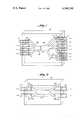
- FIG. 1is a simplified perspective view of a multiport optical distribution system embodying the invention having a differing plurality of input and output ports interconnected by several star coupler sections;
- FIG. 2is a similar perspective view, considerably simplified, of a less-complex optical distribution system embodying the invention which has only two input ports and two output ports with a unitary star coupler section interconnecting them.
- the illustrated multiport optical systemcomprises an input optical cable 10, represented as having four fiber elements, which is interconnected with a primary output optical cable 11, also having four optical fiber elements, and with a secondary output optical cable 12 having three fiber elements.
- Each of the fiber elements at the input portsis conventionally represented as having an optical fiber 10a surrounded by a concentric cladding 10b.
- each of the fiber elements at the primary output portscomprises an optical fiber 11a with cladding 11b and each of the fiber elements at the secondary output ports comprises an optical fiber 12a with cladding 12b.
- the optical star structure interconnecting the various input and output portshas three sections in the specific embodiment illustrated in FIG. 1, viz., a combining section 13a, a separating section 13b, and a further separating section 13c serially fed from one of the radiating arms of section 13b.
- Each sectionhas as many radiating arms as necessary to interconnect it with its associated ports, these arms radiating out from the end of a common optical mixer portion.
- the respective mixer portionssometimes called mixer rods, are shown at 14a, 14b, and 14c.
- the radiating arms of the star sectionsare optically interconnected with their associated fibers by a plurality of fusion splices indicated at 15, 16, and 17 for the three fiber bundles.
- the adjacent ends of mixer portions 14a and 14bare similarly joined by a fusion splice at 18; and the lowermost arm radiating out from mixer portion 14b, as viewed in FIG. 1, is joined to the end of mixer portion 14c by a similar fusion splice at 19.
- optical connectorsmay be used in place of the fusion splices, though the latter take less space and minimize optical losses.
- the optical star sections 13a, 13b, and 13care formed from bare, unclad fibers, e.g., to pure silica or other suitable glass, that have their corresponding ends fused together to form their respective mixer portions 14a, 14b, and 14c. Since, in the illustrative embodiment of FIG. 1, the star section 13a has four arms while the star section 13b has five arms, the mixer portion 14b will have a larger cross-section than mixer section 14a to which it is spliced (indicated on a slightly exaggerated scale for clarity). Similarly, mixer portion 14c will have a larger cross-section than the single arm to which it is spliced at 19 because it is interconnected to three output fibers 12. These secondary outputs may be useful for low-power needs such as for optical feedback to control a plurality of optical sources.
- the previously mentioned packing fractionis very substantially increased because the stacking/packing factor, due to spaces between the round fibers in a conventional bundled array, is totally eliminated by fusing the fibers together and because the cladding/packing factor is also completely eliminated because the individual fiber arms in the star structure are unclad. Nevertheless, light attenuation losses, which conventionally are increased by removal of fiber cladding, are kept to a low value by encasing the entire star structure in its own potting/cladding compound. In FIG. 1, this is schematically represented by rectangular block 20 of a suitable plastic compound.
- the fiber arms and mixing portions of the star elementsmay be silvered or otherwise coated with a reflecting metal film which may in turn be covered with a protective plastic coating or potted for mechanical protection and support.
- the systemis bidirectional.
- Our improved star structurecan be used to provide either or both of the combining and separating functions.
- the optical through-putis highest when the number of output ports is equal to or greater than the number of input ports. Any number of inputs or outputs from one to hundreds could conceivably be accommodated.
- the amount of optical power leaving each portdepends on the size of its fiber, and possibly on its position in an array. With only a small number of output ports, as illustrated in FIG. 1, the optical power can be made about the same in each port that is interconnected with a common mixing section even if the mixing section is relatively short.
- FIG. 2illustrates how the system structure can be considerably simplified if the numbers of input ports and output ports are equal. It is illustrated in its simplest form with only two input ports 40 and two output ports 41.
- the fibers 40aare provided with concentric cladding 40b, the latter being preferably, though not necessarily, of the plastic type.
- the two fiber elements 40a, 40bare arranged parallel to each other and their claddings are stripped off over a length slightly greater than the dimension A. They are then pinched together and fused to form the star mixing structure 42 with its two combining arms on the left and separation arms on the right, as shown. These are then encased in the potting/cladding compound 43, as previously described, which is again represented in schematic rectangular block form to simplify the drawing.
- Our inventioncan be used in any of the following types of optical fiber systems:
Landscapes
- Physics & Mathematics (AREA)
- General Physics & Mathematics (AREA)
- Optics & Photonics (AREA)
- Optical Integrated Circuits (AREA)
Abstract
Description
Claims (8)
Priority Applications (1)
| Application Number | Priority Date | Filing Date | Title |
|---|---|---|---|
| US06/233,754US4360248A (en) | 1979-04-18 | 1981-02-12 | Multiport optical communication system and optical star structure therefor |
Applications Claiming Priority (2)
| Application Number | Priority Date | Filing Date | Title |
|---|---|---|---|
| US3126479A | 1979-04-18 | 1979-04-18 | |
| US06/233,754US4360248A (en) | 1979-04-18 | 1981-02-12 | Multiport optical communication system and optical star structure therefor |
Related Parent Applications (1)
| Application Number | Title | Priority Date | Filing Date |
|---|---|---|---|
| US3126479AContinuation | 1979-04-18 | 1979-04-18 |
Publications (1)
| Publication Number | Publication Date |
|---|---|
| US4360248Atrue US4360248A (en) | 1982-11-23 |
Family
ID=26707017
Family Applications (1)
| Application Number | Title | Priority Date | Filing Date |
|---|---|---|---|
| US06/233,754Expired - LifetimeUS4360248A (en) | 1979-04-18 | 1981-02-12 | Multiport optical communication system and optical star structure therefor |
Country Status (1)
| Country | Link |
|---|---|
| US (1) | US4360248A (en) |
Cited By (54)
| Publication number | Priority date | Publication date | Assignee | Title |
|---|---|---|---|---|
| US4535440A (en)* | 1982-08-18 | 1985-08-13 | U.S. Philips Corporation | Optical multiplexer |
| US4606020A (en)* | 1984-02-03 | 1986-08-12 | The United States Of America As Represented By The Secretary Of The Army | Efficient design technique for wavelength division multiplexing |
| US4611884A (en)* | 1982-11-24 | 1986-09-16 | Magnetic Controls Company | Bi-directional optical fiber coupler |
| US4653845A (en)* | 1983-12-08 | 1987-03-31 | Northern Telecom Limited | Fiber optic star coupler |
| US4666234A (en)* | 1984-11-01 | 1987-05-19 | American Telephone And Telegraph Company | Non-tapered, butt-coupled, fused-fiber optical coupler and method of forming the same |
| US4673243A (en)* | 1984-04-10 | 1987-06-16 | Director-General Of Agency Of Industrial Science & Technology | Branch structures for rod-type optical transmission lines |
| US4687284A (en)* | 1984-09-04 | 1987-08-18 | Xerox Corporation | Bright fiber-free biconically tapered couplers |
| US4699453A (en)* | 1982-11-24 | 1987-10-13 | Magnetic Controls Company | Monolithic fiber optic coupler having total internal reflecting surface |
| US4708424A (en)* | 1984-09-21 | 1987-11-24 | Northwestern University | Transmissive single-mode fiber optics star network |
| EP0266040A3 (en)* | 1986-10-28 | 1988-08-03 | Gould Inc., | Multimode fiber optic coupler and method for making |
| US4786131A (en)* | 1987-07-28 | 1988-11-22 | Polaroid Corporation | Star coupler |
| US4842359A (en)* | 1984-09-06 | 1989-06-27 | Hitachi, Ltd. | Optical star coupler and method of manufacturing the same |
| US4869570A (en)* | 1987-02-21 | 1989-09-26 | Nippon Telegraph And Telephone Corporation | Fiber coupler and method and apparatus for manufacturing the same |
| US4900116A (en)* | 1988-12-30 | 1990-02-13 | General Dynamics Corporation, Electronics Division | Multiple pole optical filter |
| US4915469A (en)* | 1988-03-26 | 1990-04-10 | Stc Plc | Active optical fibre star couplers |
| US4948217A (en)* | 1985-08-15 | 1990-08-14 | Corning Incorporated | Optic coupler |
| US4986620A (en)* | 1985-04-19 | 1991-01-22 | U.S. Philips Corp. | Passive fiber-optic component |
| US4995692A (en)* | 1990-02-06 | 1991-02-26 | General Motors Corporation | Fiber optic star coupler |
| US5026411A (en)* | 1989-12-21 | 1991-06-25 | At&T Bell Laboratories | Fabrication of optical couplers |
| EP0416639A3 (en)* | 1989-09-08 | 1992-01-22 | Standard Elektrik Lorenz Aktiengesellschaft | Method for the fabrication of a fused optical coupler |
| EP0416640A3 (en)* | 1989-09-08 | 1992-01-22 | Standard Elektrik Lorenz Aktiengesellschaft | Method of fabrication of a fused optical coupler and coupler manufactured accordingly |
| US5091986A (en)* | 1989-11-15 | 1992-02-25 | Mitsubishi Gas Chemical Co., Ltd. | Optical divider for multimode optical fiber systems |
| DE4033932A1 (en)* | 1990-10-25 | 1992-04-30 | Daimler Benz Ag | Prodn. of optical fibre star coupler - by hot pressing of plastic fibres into solid profile, joining to same section mixer rod and locking assembly in heat-shrink tube |
| US5129021A (en)* | 1988-07-12 | 1992-07-07 | British Telecommunications Public Limited Company | Optical star couplers |
| US5135555A (en)* | 1989-12-21 | 1992-08-04 | At&T Bell Laboratories | Apparatus for fabrication of optical couplers |
| WO1992015908A1 (en)* | 1991-03-05 | 1992-09-17 | Aster Corporation | Low cost one by eight singlemode optical fiber coupler |
| US5208885A (en)* | 1992-02-27 | 1993-05-04 | At&T Bell Laboratories | Optical fiber to strip waveguide interconnect |
| US5300162A (en)* | 1990-11-29 | 1994-04-05 | Hoechst Aktiengesellschaft | Process for the production of an optical coupler for polymeric optical fibers |
| EP0459979B1 (en)* | 1988-10-07 | 1994-07-06 | Eastman Kodak Company | Method of making a fiber optic array |
| US5408556A (en)* | 1993-12-06 | 1995-04-18 | Kaptron, Inc. | 1 X N splitter for single-mode fibers and method of construction |
| US5454057A (en)* | 1994-03-15 | 1995-09-26 | Fujitsu Limited | Method for fabricating star coupler for interconnecting optical fibers and a star coupler |
| EP0683408A1 (en)* | 1994-05-20 | 1995-11-22 | SEIKOH GIKEN Co., Ltd. | Optical fibre multiplexer/demultiplexer having a reflection layer outside of an optical coupling portion |
| USRE36820E (en)* | 1995-01-13 | 2000-08-15 | Methode Electronics, Inc. | Removable optoelectronic module |
| US6179627B1 (en) | 1998-04-22 | 2001-01-30 | Stratos Lightwave, Inc. | High speed interface converter module |
| US6201704B1 (en) | 1995-01-13 | 2001-03-13 | Stratos Lightwave, Inc. | Transceive module with EMI shielding |
| US6203333B1 (en) | 1998-04-22 | 2001-03-20 | Stratos Lightwave, Inc. | High speed interface converter module |
| US6219480B1 (en)* | 1999-01-29 | 2001-04-17 | Fiberstars Incorporated | Optical coupler for coupling light between one and a plurality of light ports |
| US6220878B1 (en) | 1995-10-04 | 2001-04-24 | Methode Electronics, Inc. | Optoelectronic module with grounding means |
| US6220873B1 (en)* | 1999-08-10 | 2001-04-24 | Stratos Lightwave, Inc. | Modified contact traces for interface converter |
| GB2377505A (en)* | 2001-07-10 | 2003-01-15 | Jds Uniphase Corp | Fused optic fibre couplers |
| US20030169990A1 (en)* | 2000-08-03 | 2003-09-11 | Stephane Rio | Method for optical fibre re-cladding and resulting product |
| US7090509B1 (en) | 1999-06-11 | 2006-08-15 | Stratos International, Inc. | Multi-port pluggable transceiver (MPPT) with multiple LC duplex optical receptacles |
| US20070274632A1 (en)* | 2006-04-28 | 2007-11-29 | Gemfire Corporation | Arrayed waveguide grating with reduced channel passband asymmetry |
| USRE40150E1 (en) | 1994-04-25 | 2008-03-11 | Matsushita Electric Industrial Co., Ltd. | Fiber optic module |
| US20100008624A1 (en)* | 2008-07-14 | 2010-01-14 | Chiral Photonics, Inc. | Optical fiber coupler array |
| JP2014071171A (en)* | 2012-09-28 | 2014-04-21 | Ji Engineering Kk | Optical component, light guide member usable in optical component, and light irradiation device |
| US8712199B2 (en)* | 2008-07-14 | 2014-04-29 | Chiral Photonics, Inc. | Configurable pitch reducing optical fiber array |
| US9164241B2 (en)* | 2013-07-18 | 2015-10-20 | Honeywell International Inc. | Low loss passive optical hub for use in the plastic optical fiber networks |
| US20170164076A1 (en)* | 2015-12-04 | 2017-06-08 | Verizon Patent And Licensing Inc. | Optical network with small-form-factor optical fiber cross-connect module |
| US10838155B2 (en) | 2013-06-14 | 2020-11-17 | Chiral Photonics, Inc. | Multichannel optical coupler |
| US10914891B2 (en) | 2013-06-14 | 2021-02-09 | Chiral Photonics, Inc. | Multichannel optical coupler |
| US11156781B2 (en) | 2013-06-14 | 2021-10-26 | Chiral Photonics, Inc. | Passive aligning optical coupler array |
| US11966091B2 (en) | 2013-06-14 | 2024-04-23 | Chiral Photonics, Inc. | Multichannel optical coupler array |
| US12210185B2 (en) | 2020-02-24 | 2025-01-28 | Chiral Photonics, Inc. | Wavelength division multiplexers for space division multiplexing (SDM-WDM devices) |
Citations (7)
| Publication number | Priority date | Publication date | Assignee | Title |
|---|---|---|---|---|
| US3825319A (en)* | 1973-02-26 | 1974-07-23 | Bell Telephone Labor Inc | Butt-joined optical fibers |
| US3933455A (en)* | 1973-06-14 | 1976-01-20 | International Standard Electric Corporation | Method for joining optical fibre bundles |
| DE2712054A1 (en)* | 1976-03-22 | 1977-10-06 | Int Standard Electric Corp | COUPLING ARRANGEMENT FOR LIGHT GUIDE |
| US4054366A (en)* | 1976-07-12 | 1977-10-18 | Hughes Aircraft Company | Fiber optics access coupler |
| US4083625A (en)* | 1976-08-02 | 1978-04-11 | Corning Glass Works | Optical fiber junction device |
| US4087156A (en)* | 1975-11-07 | 1978-05-02 | International Telephone & Telegraph Corporation | Optical fiber transmission mixer and method of making same |
| US4136929A (en)* | 1974-11-29 | 1979-01-30 | Hitachi, Ltd. | Apparatus for generating light pulse train |
- 1981
- 1981-02-12USUS06/233,754patent/US4360248A/ennot_activeExpired - Lifetime
Patent Citations (7)
| Publication number | Priority date | Publication date | Assignee | Title |
|---|---|---|---|---|
| US3825319A (en)* | 1973-02-26 | 1974-07-23 | Bell Telephone Labor Inc | Butt-joined optical fibers |
| US3933455A (en)* | 1973-06-14 | 1976-01-20 | International Standard Electric Corporation | Method for joining optical fibre bundles |
| US4136929A (en)* | 1974-11-29 | 1979-01-30 | Hitachi, Ltd. | Apparatus for generating light pulse train |
| US4087156A (en)* | 1975-11-07 | 1978-05-02 | International Telephone & Telegraph Corporation | Optical fiber transmission mixer and method of making same |
| DE2712054A1 (en)* | 1976-03-22 | 1977-10-06 | Int Standard Electric Corp | COUPLING ARRANGEMENT FOR LIGHT GUIDE |
| US4054366A (en)* | 1976-07-12 | 1977-10-18 | Hughes Aircraft Company | Fiber optics access coupler |
| US4083625A (en)* | 1976-08-02 | 1978-04-11 | Corning Glass Works | Optical fiber junction device |
Non-Patent Citations (3)
| Title |
|---|
| Barnoski, "Fundamentals of Optical Fiber Communications," Academic Press Inc., New York 1976, pp. 210-213.* |
| K. Ogawa et al., "Multimode Fiber Coupler," Applied Optics, vol. 17, No. 13, Jul. 1978.* |
| K. Ogawa, "Multimode Fiber Coupler-Theory and Experiment," Optical Fiber Transmission II, Williamsburg, Virginia, WB7-1, Feb. 1977.* |
Cited By (66)
| Publication number | Priority date | Publication date | Assignee | Title |
|---|---|---|---|---|
| US4535440A (en)* | 1982-08-18 | 1985-08-13 | U.S. Philips Corporation | Optical multiplexer |
| US4611884A (en)* | 1982-11-24 | 1986-09-16 | Magnetic Controls Company | Bi-directional optical fiber coupler |
| US4699453A (en)* | 1982-11-24 | 1987-10-13 | Magnetic Controls Company | Monolithic fiber optic coupler having total internal reflecting surface |
| US4653845A (en)* | 1983-12-08 | 1987-03-31 | Northern Telecom Limited | Fiber optic star coupler |
| US4606020A (en)* | 1984-02-03 | 1986-08-12 | The United States Of America As Represented By The Secretary Of The Army | Efficient design technique for wavelength division multiplexing |
| US4673243A (en)* | 1984-04-10 | 1987-06-16 | Director-General Of Agency Of Industrial Science & Technology | Branch structures for rod-type optical transmission lines |
| US4687284A (en)* | 1984-09-04 | 1987-08-18 | Xerox Corporation | Bright fiber-free biconically tapered couplers |
| US4842359A (en)* | 1984-09-06 | 1989-06-27 | Hitachi, Ltd. | Optical star coupler and method of manufacturing the same |
| US4708424A (en)* | 1984-09-21 | 1987-11-24 | Northwestern University | Transmissive single-mode fiber optics star network |
| US4666234A (en)* | 1984-11-01 | 1987-05-19 | American Telephone And Telegraph Company | Non-tapered, butt-coupled, fused-fiber optical coupler and method of forming the same |
| US4986620A (en)* | 1985-04-19 | 1991-01-22 | U.S. Philips Corp. | Passive fiber-optic component |
| US4948217A (en)* | 1985-08-15 | 1990-08-14 | Corning Incorporated | Optic coupler |
| EP0266040A3 (en)* | 1986-10-28 | 1988-08-03 | Gould Inc., | Multimode fiber optic coupler and method for making |
| US4869570A (en)* | 1987-02-21 | 1989-09-26 | Nippon Telegraph And Telephone Corporation | Fiber coupler and method and apparatus for manufacturing the same |
| US4786131A (en)* | 1987-07-28 | 1988-11-22 | Polaroid Corporation | Star coupler |
| US4915469A (en)* | 1988-03-26 | 1990-04-10 | Stc Plc | Active optical fibre star couplers |
| US5129021A (en)* | 1988-07-12 | 1992-07-07 | British Telecommunications Public Limited Company | Optical star couplers |
| EP0459979B1 (en)* | 1988-10-07 | 1994-07-06 | Eastman Kodak Company | Method of making a fiber optic array |
| US4900116A (en)* | 1988-12-30 | 1990-02-13 | General Dynamics Corporation, Electronics Division | Multiple pole optical filter |
| US5129019A (en)* | 1989-09-08 | 1992-07-07 | Alcatel N.V. | Method of manufacturing a fused-fiber optical coupler |
| EP0416639A3 (en)* | 1989-09-08 | 1992-01-22 | Standard Elektrik Lorenz Aktiengesellschaft | Method for the fabrication of a fused optical coupler |
| EP0416640A3 (en)* | 1989-09-08 | 1992-01-22 | Standard Elektrik Lorenz Aktiengesellschaft | Method of fabrication of a fused optical coupler and coupler manufactured accordingly |
| US5091986A (en)* | 1989-11-15 | 1992-02-25 | Mitsubishi Gas Chemical Co., Ltd. | Optical divider for multimode optical fiber systems |
| US5026411A (en)* | 1989-12-21 | 1991-06-25 | At&T Bell Laboratories | Fabrication of optical couplers |
| US5135555A (en)* | 1989-12-21 | 1992-08-04 | At&T Bell Laboratories | Apparatus for fabrication of optical couplers |
| US4995692A (en)* | 1990-02-06 | 1991-02-26 | General Motors Corporation | Fiber optic star coupler |
| DE4033932A1 (en)* | 1990-10-25 | 1992-04-30 | Daimler Benz Ag | Prodn. of optical fibre star coupler - by hot pressing of plastic fibres into solid profile, joining to same section mixer rod and locking assembly in heat-shrink tube |
| US5300162A (en)* | 1990-11-29 | 1994-04-05 | Hoechst Aktiengesellschaft | Process for the production of an optical coupler for polymeric optical fibers |
| WO1992015908A1 (en)* | 1991-03-05 | 1992-09-17 | Aster Corporation | Low cost one by eight singlemode optical fiber coupler |
| US5166994A (en)* | 1991-03-05 | 1992-11-24 | Aster Corporation | Low cost one by eight singlemode optical fiber coupler |
| US5208885A (en)* | 1992-02-27 | 1993-05-04 | At&T Bell Laboratories | Optical fiber to strip waveguide interconnect |
| US5408556A (en)* | 1993-12-06 | 1995-04-18 | Kaptron, Inc. | 1 X N splitter for single-mode fibers and method of construction |
| US5454057A (en)* | 1994-03-15 | 1995-09-26 | Fujitsu Limited | Method for fabricating star coupler for interconnecting optical fibers and a star coupler |
| USRE40154E1 (en) | 1994-04-25 | 2008-03-18 | Matsushita Electric Industrial Co., Ltd. | Fiber optic module |
| USRE40150E1 (en) | 1994-04-25 | 2008-03-11 | Matsushita Electric Industrial Co., Ltd. | Fiber optic module |
| EP0683408A1 (en)* | 1994-05-20 | 1995-11-22 | SEIKOH GIKEN Co., Ltd. | Optical fibre multiplexer/demultiplexer having a reflection layer outside of an optical coupling portion |
| US6267606B1 (en) | 1995-01-13 | 2001-07-31 | Stratos Lightwave, Inc. | Removable transceiver module and receptacle |
| US6201704B1 (en) | 1995-01-13 | 2001-03-13 | Stratos Lightwave, Inc. | Transceive module with EMI shielding |
| USRE36820E (en)* | 1995-01-13 | 2000-08-15 | Methode Electronics, Inc. | Removable optoelectronic module |
| US6220878B1 (en) | 1995-10-04 | 2001-04-24 | Methode Electronics, Inc. | Optoelectronic module with grounding means |
| US6203333B1 (en) | 1998-04-22 | 2001-03-20 | Stratos Lightwave, Inc. | High speed interface converter module |
| US6179627B1 (en) | 1998-04-22 | 2001-01-30 | Stratos Lightwave, Inc. | High speed interface converter module |
| US6219480B1 (en)* | 1999-01-29 | 2001-04-17 | Fiberstars Incorporated | Optical coupler for coupling light between one and a plurality of light ports |
| US7090509B1 (en) | 1999-06-11 | 2006-08-15 | Stratos International, Inc. | Multi-port pluggable transceiver (MPPT) with multiple LC duplex optical receptacles |
| US6220873B1 (en)* | 1999-08-10 | 2001-04-24 | Stratos Lightwave, Inc. | Modified contact traces for interface converter |
| US6915043B2 (en)* | 2000-08-03 | 2005-07-05 | Highwave Optical Technologies | Method of re-cladding an optical fiber and product thus obtained |
| US20030169990A1 (en)* | 2000-08-03 | 2003-09-11 | Stephane Rio | Method for optical fibre re-cladding and resulting product |
| US6839490B2 (en) | 2001-07-10 | 2005-01-04 | Jds Uniphase Corporation | Method of making sequential coupler arrangements and resulting devices |
| US20030012506A1 (en)* | 2001-07-10 | 2003-01-16 | Jones Julian Kelly | Method of making sequential coupler arrangements and resulting devices |
| GB2377505A (en)* | 2001-07-10 | 2003-01-15 | Jds Uniphase Corp | Fused optic fibre couplers |
| US7492991B2 (en) | 2006-04-28 | 2009-02-17 | Gemfire Corporation | Arrayed waveguide grating with reduced channel passband asymmetry |
| US20070274632A1 (en)* | 2006-04-28 | 2007-11-29 | Gemfire Corporation | Arrayed waveguide grating with reduced channel passband asymmetry |
| US20150212274A1 (en)* | 2008-07-14 | 2015-07-30 | Victor Il'ich Kopp | Optimized Configurable Pitch Reducing Optical Fiber Coupler Array |
| US8712199B2 (en)* | 2008-07-14 | 2014-04-29 | Chiral Photonics, Inc. | Configurable pitch reducing optical fiber array |
| US8326099B2 (en)* | 2008-07-14 | 2012-12-04 | Chiral Photonics, Inc. | Optical fiber coupler array |
| US20100008624A1 (en)* | 2008-07-14 | 2010-01-14 | Chiral Photonics, Inc. | Optical fiber coupler array |
| US10564360B2 (en)* | 2008-07-14 | 2020-02-18 | Chiral Photonics, Inc. | Optimized configurable pitch reducing optical fiber coupler array |
| JP2014071171A (en)* | 2012-09-28 | 2014-04-21 | Ji Engineering Kk | Optical component, light guide member usable in optical component, and light irradiation device |
| US11156781B2 (en) | 2013-06-14 | 2021-10-26 | Chiral Photonics, Inc. | Passive aligning optical coupler array |
| US11966091B2 (en) | 2013-06-14 | 2024-04-23 | Chiral Photonics, Inc. | Multichannel optical coupler array |
| US10838155B2 (en) | 2013-06-14 | 2020-11-17 | Chiral Photonics, Inc. | Multichannel optical coupler |
| US10914891B2 (en) | 2013-06-14 | 2021-02-09 | Chiral Photonics, Inc. | Multichannel optical coupler |
| US9164241B2 (en)* | 2013-07-18 | 2015-10-20 | Honeywell International Inc. | Low loss passive optical hub for use in the plastic optical fiber networks |
| US20170164076A1 (en)* | 2015-12-04 | 2017-06-08 | Verizon Patent And Licensing Inc. | Optical network with small-form-factor optical fiber cross-connect module |
| US9877091B2 (en)* | 2015-12-04 | 2018-01-23 | Verizon Patent And Licensing Inc. | Optical network with small-form-factor optical fiber cross-connect module |
| US12210185B2 (en) | 2020-02-24 | 2025-01-28 | Chiral Photonics, Inc. | Wavelength division multiplexers for space division multiplexing (SDM-WDM devices) |
Similar Documents
| Publication | Publication Date | Title |
|---|---|---|
| US4360248A (en) | Multiport optical communication system and optical star structure therefor | |
| US4179185A (en) | Coupler for optical communication system | |
| CA1143978A (en) | Passive fiber optic data bus configurations | |
| US5757994A (en) | Three-part optical coupler | |
| US3874781A (en) | Coupler for optical communication system | |
| US3870396A (en) | Optical coupler | |
| US4784452A (en) | Optical fiber coupler | |
| US4550975A (en) | Optical coupling devices | |
| US4054366A (en) | Fiber optics access coupler | |
| CA1141215A (en) | Optical fiber beam splitter couplers employing coatings with dichroic properties | |
| US4234969A (en) | Bidirectional optical coupler for a data processing system | |
| US4479697A (en) | Fiber optics communications modules | |
| US3870398A (en) | Passive coupler for optical communication system | |
| US3883222A (en) | Coupler for optical communication system | |
| US3917383A (en) | Optical waveguide bundle connector | |
| US6031952A (en) | Broadband coupler | |
| EP0725289B1 (en) | Optical coupler using ferrules with four polarization maintaining optical fibres | |
| US5666448A (en) | Variable splitting optical coupler | |
| US4213670A (en) | Planar fiber optic star and access coupler | |
| CA1325123C (en) | Non-invasive optical coupler | |
| US4600267A (en) | Optical distributor | |
| US5074634A (en) | Optical multiplexing/demultiplexing device | |
| JP3391650B2 (en) | Optical splitter | |
| US8855457B2 (en) | Optical splitting component | |
| JP3311040B2 (en) | Optical fiber branch component and manufacturing method thereof |
Legal Events
| Date | Code | Title | Description |
|---|---|---|---|
| STCF | Information on status: patent grant | Free format text:PATENTED CASE | |
| AS | Assignment | Owner name:ITT CORPORATION Free format text:CHANGE OF NAME;ASSIGNOR:INTERNATIONAL TELEPHONE AND TELEGRAPH CORPORATION;REEL/FRAME:004389/0606 Effective date:19831122 | |
| MAFP | Maintenance fee payment | Free format text:PAYMENT OF MAINTENANCE FEE, 4TH YEAR, PL 96-517 (ORIGINAL EVENT CODE: M170); ENTITY STATUS OF PATENT OWNER: LARGE ENTITY Year of fee payment:4 | |
| AS | Assignment | Owner name:U.S. HOLDING COMPANY, INC., C/O ALCATEL USA CORP., Free format text:ASSIGNMENT OF ASSIGNORS INTEREST. EFFECTIVE 3/11/87;ASSIGNOR:ITT CORPORATION;REEL/FRAME:004718/0039 Effective date:19870311 | |
| AS | Assignment | Owner name:ALCATEL USA, CORP. Free format text:CHANGE OF NAME;ASSIGNOR:U.S. HOLDING COMPANY, INC.;REEL/FRAME:004827/0276 Effective date:19870910 Owner name:ALCATEL USA, CORP.,STATELESS Free format text:CHANGE OF NAME;ASSIGNOR:U.S. HOLDING COMPANY, INC.;REEL/FRAME:004827/0276 Effective date:19870910 | |
| MAFP | Maintenance fee payment | Free format text:PAYMENT OF MAINTENANCE FEE, 8TH YEAR, PL 96-517 (ORIGINAL EVENT CODE: M171); ENTITY STATUS OF PATENT OWNER: LARGE ENTITY Year of fee payment:8 | |
| FEPP | Fee payment procedure | Free format text:PAYOR NUMBER ASSIGNED (ORIGINAL EVENT CODE: ASPN); ENTITY STATUS OF PATENT OWNER: LARGE ENTITY | |
| AS | Assignment | Owner name:ALCATEL NA CABLE SYSTEMS, INC. A CORP. OF DELAWA Free format text:ASSIGNMENT OF ASSIGNORS INTEREST.;ASSIGNOR:ALCATEL USA CORP. A CORP. OF DELAWARE;REEL/FRAME:005712/0033 Effective date:19910520 | |
| MAFP | Maintenance fee payment | Free format text:PAYMENT OF MAINTENANCE FEE, 12TH YEAR, LARGE ENTITY (ORIGINAL EVENT CODE: M185); ENTITY STATUS OF PATENT OWNER: LARGE ENTITY Year of fee payment:12 | |
| FEPP | Fee payment procedure | Free format text:PAYOR NUMBER ASSIGNED (ORIGINAL EVENT CODE: ASPN); ENTITY STATUS OF PATENT OWNER: LARGE ENTITY Free format text:PAYER NUMBER DE-ASSIGNED (ORIGINAL EVENT CODE: RMPN); ENTITY STATUS OF PATENT OWNER: LARGE ENTITY |