US4360031A - Drug dispensing irrigatable electrode - Google Patents
Drug dispensing irrigatable electrodeDownload PDFInfo
- Publication number
- US4360031A US4360031AUS06/186,106US18610680AUS4360031AUS 4360031 AUS4360031 AUS 4360031AUS 18610680 AUS18610680 AUS 18610680AUS 4360031 AUS4360031 AUS 4360031A
- Authority
- US
- United States
- Prior art keywords
- conductor
- inner sheath
- sheath
- electrode
- pacing lead
- Prior art date
- Legal status (The legal status is an assumption and is not a legal conclusion. Google has not performed a legal analysis and makes no representation as to the accuracy of the status listed.)
- Expired - Lifetime
Links
Images


Classifications
- A—HUMAN NECESSITIES
- A61—MEDICAL OR VETERINARY SCIENCE; HYGIENE
- A61N—ELECTROTHERAPY; MAGNETOTHERAPY; RADIATION THERAPY; ULTRASOUND THERAPY
- A61N1/00—Electrotherapy; Circuits therefor
- A61N1/02—Details
- A61N1/04—Electrodes
- A61N1/05—Electrodes for implantation or insertion into the body, e.g. heart electrode
- A61N1/056—Transvascular endocardial electrode systems
- A61N1/0565—Electrode heads
- A61N1/0568—Electrode heads with drug delivery
Definitions
- the present inventionrelates generally to implantable medical apparatus and more specifically relates to a cardiac pacing lead having structure for dispensing chemical agents.
- Electrodesexist which dispense chemical agents.
- U.S. Pat. No. 623,022 issued to Johnsonteaches an early drug dispensing electrode. More recent drug dispensing electrodes are taught by U.S. Pat. Nos. 3,533,403; 3,680,544 and 3,817,241 issued to Woodson, Shinnick and Grausz, respectively. However, all of these devices are suitable for acute use only and are not usable for chronic implantation.
- pacing thresholdscan be substantially lowered using treatment of endocardial tissue by steroids and other chemical agents. Notice that the important feature for such a technique is the dispensing of the drug to the same tissue which is receiving the electrical stimulus. It is for that reason that the chronically implantable drug dispensers taught by U.S. Pat. Nos. 3,527,220; 3,692,027 and 4,146,029 issued to Summers, Ellinwood, Jr. and Ellinwood, Jr., respectively are not acceptable for this purpose. Furthermore, these chronically implantable drug dispensers are far more complex than is required here since they automatically dispense drugs over a relatively long period of time. The present invention, though chronically implantable, provides only discretionary drug therapy by direct action of the attending physician.
- the present inventionis a permanent transvenous cardiac pacing lead.
- the ring tip electrode of the pacing leadhas a number of apertures through which a chemical agent may be dispensed.
- the aperturesare connected to a tube which runs the length of the lead.
- the tubehas a connector through which the stylet may be inserted and removed.
- the styletis removed and the tube is coupled to a bladder.
- the purpose of the bladderis to implant a device of sufficient size to enable a physician to easily infuse a chemical agent. The bladder does not store the drug for subsequent release.
- the physicianmay percutaneously dispense chemical agents via the apertures in the tip electrode by inserting a syringe into the subcutaneously located bladder. It is anticipated that the attending physician will thereby be able to readily irrigate and dispense steroids to the endocardial tissue in contact with the ring tip electrode at any time during the pacing therapy. This technique, it is felt, will alleviate trauma and permit chronic maintenance of substantially reduced pacing thresholds.
- FIG. 1is a plan view of a permanent transvenous lead incorporating the present invention.
- FIG. 2is a front sectional view of the tip electrode.
- FIG. 3is a front sectional view showing the reed valve.
- FIG. 4is a front sectional view showing the stylet restraint.
- FIG. 5is a front sectional view of the main body of the lead proximal to the indifferent electrode.
- FIG. 6is a side sectional view of the distal end of the lead.
- FIG. 7is a top sectional view of connector 20.
- FIG. 8is a top sectional view of bladder 34.
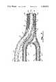
- FIG. 9schematically shows post-implant irrigation of endocardial tissue using the present invention.
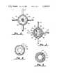
- FIG. 1is a plan view of a pacing lead incorporating the preferred embodiment of the present invention.
- ring tip electrode 40containing side apertures 42, 44, 46 and 48 (apertures 46 and 48 are not shown).
- Tines 14are used to inhibit dislodgement during chronic implantation.
- Ring electrode 12serves as the indifferent electrode as with most bipolar pacing systems.
- outer sheath 10which is of a material substantially inert to body fluids, such as urethane or silicon rubber. Outer sheath 10 must also be an electrical insulator.
- Connector 20is located at the proximal end of the pacing lead. Electrical connector pins 22a and 22b are inserted into a pulse generator to complete the electrical circuit. Electrical connector pin 22a is electrically coupled to ring tip electrode 40 via an inner conductor (not shown). Electrical connector pin 22b is electrically coupled to ring electrode 12 via an outer conductor (not shown). Sealing rings 24 are used to seal the electrical connection between electrical connector pins 22a and 22b from the ingress of body fluids.
- Connector 20also includes fluid coupling arm 26 which is shown connected to tubing 30 via fluid connector 32.
- Fluid coupling arm 26is so constructed that with tubing 30 not connected at fluid connector 32, a stylet is easily inserted into fluid coupling arm 26 and thence into the tube within the main body of the pacing lead. This is accomplished by ensuring that fluid coupling arm 26 has no sharp bends and meets connector 20 and the main body of the pacing lead via smooth curves.
- Bladder 34is coupled to tubing 30 which is in turn coupled via fluid connector 32 to fluid connector arm 26.
- Bladder 34is thin and quite inflexible as storage of the chemical agent is undesirable but it must be impervious to the desired chemical agents.
- a hypodermic syringeis percutaneously inserted into bladder 34 for dispensing drugs and irrigating the endocardial tissue. Bladder 34 must reseal itself upon removal of the hypodermic syringe. The infusate force of the hypodermic syring is sufficient to force dispensing of the drug or irrigation to the endocardial tissue via the apertures in ring tip electrode 40.
- FIG. 2is a front sectional view of the distal end of the pacing lead. Ring tip electrode 40 is shown. Element 52 is a dielectric material such as silicon rubber or urethane. The cross hatched area immediately surrounding aperture 50 signifies that element 52 is cross sectioned in that area in this view. Aperture 50 is shown as in addition to apertures 42, 44, 46 and 48 (not seen in FIG. 2). These apertures are small, being of the order of 0.005 inch. Tines 14 are shown. Tines 14 are made from the same material as outer sheath 10. See U.S. Pat. No. 3,902,501 issued to Citron et al, for a further discussion of tines 14.
- FIG. 3is a front sectional view showing reed valve assembly 54 containing individual reed valves 56 and 58.
- Reed valve assembly 54permits fluid flow in a more distal direction but prevents fluid flow in a more proximal direction. This is necessary to prevent body fluids from diffusing into the tube in the main body of the pacing lead and eventually into bladder 34. Apertures 42, 44, 46 and 48 are also shown. By reference to FIG. 6, the relative position of reed valve assembly 54 may be ascertained.
- FIG. 4is a front sectional view showing the detail of stylet restraint 60.
- FIG. 6shows the relative position of stylet restraint 60.
- stylet restraint 60contains a relatively large aperture 62 which is on the order of 0.010-0.012 inch. This aperture provides for passage of the chemical agent to be dispensed but prohibits passage of a stylet being typically 0.014 inch or larger.
- Stylet restraint 60prevents a stylet from damaging reed valve assembly 54 during implantation.
- FIG. 5is a cross-sectional view of the main body of the pacing lead as seen proximal of ring electrode 12.
- Outer sheath 10insulates outer conductor 16 from exposure to body fluids and tissue.
- Outer conductor 16is a helically wound coil of flexible, highly conductive wire as commonly used in cardiac pacing leads.
- Intermediate sheath 18is a dielectric which insulates outer conductor 16 from inner conductor 17.
- Inner conductor 17is of a construction similar to outer conductor 16.
- Inner sheath 19seals and insulates inner conductor 17 from the chemical agent to be dispensed.
- Tube 11is the area within inner sheath 19 through which the stylet is inserted at implantation and through which the chemical agent travels for dispensing.
- FIG. 6is a side sectional view of the distal end of the pacing lead.
- Outer conductor 16 and intermediate sheath 18are terminated just distal of ring electrode 12 (not shown) using techniques known in the art.
- Inner sheath 19defines tube 11 as explained above.
- Stylet restraint 60 having aperture 62is shown in position.
- Reed valve assembly 54is shown with reed valves 56 and 58. Reed valves 56 and 58 open distally as shown.
- Reed valve assembly 54 and stylet restraint 60should be made of a material impervious to body fluids and the chemical agents to be dispensed. Titanium is a preferred material.
- the chemical agent to be dispensedtravels in a distal direction in tube 11 and passes stylet restraint 60 via aperture 62.
- Reed valves 56 and 58open distally permitting the chemical agent to be forced through apertures 42, 44, 46, 48 and 50 (only 46, 48 and 50 are shown).
- Dielectric material 52is silicon rubber or other suitable material which fills the void within ring tip electrode 40 thereby assuring more positive control of the dispensing process by the attending physician.
- the volume required to permit reed valves 56 and 58 to open and the chemical agent to flow to apertures 42, 44, 46, 48 and 50is minimized to minimize the amount of chemical agent not immediately dispensed.
- Inner conductor 17is firmly attached to ring tip electrode 40 by welding or frictionally by swaging or crimping.
- Outer sheath 10is molded or shrink fit to ring tip electrode 40 to provide a tight seal.
- Reed valve assembly 54 and stylet restraint 60are attached to electrode 40 by welds 57 and 59.
- FIG. 7is a top sectional view showing a portion of connector 20.
- Outer sheath 10is shown as covering the entire assembly.
- Outer conductor 16goes to connector pin 22b.
- Inner conductor 17goes to connector pin 22a. See also FIG. 1.
- Intermediate sheath 18terminates as outer conductor 16 and inner conductor 17 separate.
- Inner sheath 19extends through fluid coupling arm 26.
- fluid coupling arm 26must not have sharp bends causing difficulty for insertion of the stylet.
- Reference 13indicates the position of the stylet during implantation and the flow of a chemical agent during dispensing or irrigation.
- FIG. 8is a top sectional view of bladder 34. Notice that tubing 30 may be molded directly to bladder 34, which simply becomes a flat enlargement of tubing 30.
- Metal plate 36is located within bladder 34 to prevent a hypodermic syringe from puncturing both walls of bladder 34 enabling the chemical agent to be dispensed external to bladder 34.
- Metal plate 36is also opaque to diagnostic radiation permitting bladder 34 to be readily located under fluoroscopy.
- FIG. 9is a schematic view of the preferred embodiment in use.
- the distal end of the pacing leadis placed into vein 72 at aperture 74.
- Ring tip electrode 40is caused to be located at the apex of the right ventricle of the heart 70.
- the proximal end of the pacing leadis arranged such that pulse generator 76 may be conveniently located and connected via connector 20.
- Tubing 30is coupled to fluid coupling arm 26 via fluid connector 32.
- Bladder 34is implanted subcutaneously at a convenient location.
- the attending physicianmay administer a chemical agent by percutaneously inserting hypodermic syringe 80 into bladder 34. Pressure on plunger 82 causes the chemical agent to be transferred from hypodermic syringe 80 to bladder 34 and thence into heart 70 from the apertures in ring tip electrode 40 as shown.
- bipolar pacing leadhaving been disclosed, those skilled in the art will readily be able to design a unipolar pacing lead incorporating the present invention.
Landscapes
- Health & Medical Sciences (AREA)
- Heart & Thoracic Surgery (AREA)
- Engineering & Computer Science (AREA)
- Biomedical Technology (AREA)
- Radiology & Medical Imaging (AREA)
- Bioinformatics & Cheminformatics (AREA)
- Vascular Medicine (AREA)
- Cardiology (AREA)
- Chemical & Material Sciences (AREA)
- Nuclear Medicine, Radiotherapy & Molecular Imaging (AREA)
- Medicinal Chemistry (AREA)
- Life Sciences & Earth Sciences (AREA)
- Animal Behavior & Ethology (AREA)
- General Health & Medical Sciences (AREA)
- Public Health (AREA)
- Veterinary Medicine (AREA)
- Electrotherapy Devices (AREA)
Abstract
Description
1. Field of the Invention
The present invention relates generally to implantable medical apparatus and more specifically relates to a cardiac pacing lead having structure for dispensing chemical agents.
2. Discussion of the Prior Art
Electrodes exist which dispense chemical agents. U.S. Pat. No. 623,022 issued to Johnson teaches an early drug dispensing electrode. More recent drug dispensing electrodes are taught by U.S. Pat. Nos. 3,533,403; 3,680,544 and 3,817,241 issued to Woodson, Shinnick and Grausz, respectively. However, all of these devices are suitable for acute use only and are not usable for chronic implantation.
What is desired is a chronically implantable transvenous cardiac pacing lead having the capability for discretionary chemical treatement to enhance pacing therapy. Tests have shown that pacing thresholds can be substantially lowered using treatment of endocardial tissue by steroids and other chemical agents. Notice that the important feature for such a technique is the dispensing of the drug to the same tissue which is receiving the electrical stimulus. It is for that reason that the chronically implantable drug dispensers taught by U.S. Pat. Nos. 3,527,220; 3,692,027 and 4,146,029 issued to Summers, Ellinwood, Jr. and Ellinwood, Jr., respectively are not acceptable for this purpose. Furthermore, these chronically implantable drug dispensers are far more complex than is required here since they automatically dispense drugs over a relatively long period of time. The present invention, though chronically implantable, provides only discretionary drug therapy by direct action of the attending physician.
The present invention is a permanent transvenous cardiac pacing lead. The ring tip electrode of the pacing lead has a number of apertures through which a chemical agent may be dispensed. The apertures are connected to a tube which runs the length of the lead. By locating the tube coaxially and internally in the conducting coils of the lead, a stylet may be inserted in the tube to assist in implantation, thereby not requiring any addition to the cross-sectional area of the lead.
At the proximal end of the lead, the tube has a connector through which the stylet may be inserted and removed. After the ring tip electrode is properly positioned, the stylet is removed and the tube is coupled to a bladder. The purpose of the bladder is to implant a device of sufficient size to enable a physician to easily infuse a chemical agent. The bladder does not store the drug for subsequent release.
After implant, the physician may percutaneously dispense chemical agents via the apertures in the tip electrode by inserting a syringe into the subcutaneously located bladder. It is anticipated that the attending physician will thereby be able to readily irrigate and dispense steroids to the endocardial tissue in contact with the ring tip electrode at any time during the pacing therapy. This technique, it is felt, will alleviate trauma and permit chronic maintenance of substantially reduced pacing thresholds.
FIG. 1 is a plan view of a permanent transvenous lead incorporating the present invention.
FIG. 2 is a front sectional view of the tip electrode.
FIG. 3 is a front sectional view showing the reed valve.
FIG. 4 is a front sectional view showing the stylet restraint.
FIG. 5 is a front sectional view of the main body of the lead proximal to the indifferent electrode.
FIG. 6 is a side sectional view of the distal end of the lead.
FIG. 7 is a top sectional view ofconnector 20.
FIG. 8 is a top sectional view ofbladder 34.
FIG. 9 schematically shows post-implant irrigation of endocardial tissue using the present invention.
The preferred mode of the present invention herein disclosed is embodied in a drug dispensing, permanent, bipolar, transvenous, ventricular pacing lead. Those skilled in the art will readily be able to apply this invention to other configurations.
FIG. 1 is a plan view of a pacing lead incorporating the preferred embodiment of the present invention. At the distal end of the pacing lead isring tip electrode 40 containingside apertures apertures Tines 14 are used to inhibit dislodgement during chronic implantation.Ring electrode 12 serves as the indifferent electrode as with most bipolar pacing systems.
The main body of the pacing lead is covered byouter sheath 10 which is of a material substantially inert to body fluids, such as urethane or silicon rubber.Outer sheath 10 must also be an electrical insulator.Connector 20 is located at the proximal end of the pacing lead.Electrical connector pins Electrical connector pin 22a is electrically coupled toring tip electrode 40 via an inner conductor (not shown).Electrical connector pin 22b is electrically coupled toring electrode 12 via an outer conductor (not shown).Sealing rings 24 are used to seal the electrical connection betweenelectrical connector pins
FIG. 2 is a front sectional view of the distal end of the pacing lead.Ring tip electrode 40 is shown.Element 52 is a dielectric material such as silicon rubber or urethane. The cross hatched area immediately surroundingaperture 50 signifies thatelement 52 is cross sectioned in that area in this view.Aperture 50 is shown as in addition toapertures Tines 14 are shown.Tines 14 are made from the same material asouter sheath 10. See U.S. Pat. No. 3,902,501 issued to Citron et al, for a further discussion oftines 14.
FIG. 3 is a front sectional view showingreed valve assembly 54 containingindividual reed valves Reed valve assembly 54 permits fluid flow in a more distal direction but prevents fluid flow in a more proximal direction. This is necessary to prevent body fluids from diffusing into the tube in the main body of the pacing lead and eventually intobladder 34.Apertures reed valve assembly 54 may be ascertained.
FIG. 4 is a front sectional view showing the detail ofstylet restraint 60. FIG. 6 shows the relative position ofstylet restraint 60. Referring again to FIG. 4, it can be seen thatstylet restraint 60 contains a relativelylarge aperture 62 which is on the order of 0.010-0.012 inch. This aperture provides for passage of the chemical agent to be dispensed but prohibits passage of a stylet being typically 0.014 inch or larger.Stylet restraint 60 prevents a stylet from damagingreed valve assembly 54 during implantation.
FIG. 5 is a cross-sectional view of the main body of the pacing lead as seen proximal ofring electrode 12.Outer sheath 10 insulatesouter conductor 16 from exposure to body fluids and tissue.Outer conductor 16 is a helically wound coil of flexible, highly conductive wire as commonly used in cardiac pacing leads.Intermediate sheath 18 is a dielectric which insulatesouter conductor 16 frominner conductor 17.Inner conductor 17 is of a construction similar toouter conductor 16.Inner sheath 19 seals and insulatesinner conductor 17 from the chemical agent to be dispensed. Tube 11 is the area withininner sheath 19 through which the stylet is inserted at implantation and through which the chemical agent travels for dispensing.
FIG. 6 is a side sectional view of the distal end of the pacing lead.Outer conductor 16 andintermediate sheath 18 are terminated just distal of ring electrode 12 (not shown) using techniques known in the art.Inner conductor 17, therefore, becomes the only conductor.Inner sheath 19 defines tube 11 as explained above.Stylet restraint 60 havingaperture 62 is shown in position.Reed valve assembly 54 is shown withreed valves Reed valves Reed valve assembly 54 andstylet restraint 60 should be made of a material impervious to body fluids and the chemical agents to be dispensed. Titanium is a preferred material.
The chemical agent to be dispensed travels in a distal direction in tube 11 and passesstylet restraint 60 viaaperture 62.Reed valves apertures Dielectric material 52 is silicon rubber or other suitable material which fills the void withinring tip electrode 40 thereby assuring more positive control of the dispensing process by the attending physician. The volume required to permitreed valves apertures
FIG. 7 is a top sectional view showing a portion ofconnector 20.Outer sheath 10 is shown as covering the entire assembly.Outer conductor 16 goes toconnector pin 22b.Inner conductor 17 goes toconnector pin 22a. See also FIG. 1.Intermediate sheath 18 terminates asouter conductor 16 andinner conductor 17 separate.
FIG. 8 is a top sectional view ofbladder 34. Notice thattubing 30 may be molded directly tobladder 34, which simply becomes a flat enlargement oftubing 30.Metal plate 36 is located withinbladder 34 to prevent a hypodermic syringe from puncturing both walls ofbladder 34 enabling the chemical agent to be dispensed external tobladder 34.Metal plate 36 is also opaque to diagnosticradiation permitting bladder 34 to be readily located under fluoroscopy.
FIG. 9 is a schematic view of the preferred embodiment in use. The distal end of the pacing lead is placed intovein 72 ataperture 74.Ring tip electrode 40 is caused to be located at the apex of the right ventricle of theheart 70. The proximal end of the pacing lead is arranged such thatpulse generator 76 may be conveniently located and connected viaconnector 20.Tubing 30 is coupled tofluid coupling arm 26 viafluid connector 32.Bladder 34 is implanted subcutaneously at a convenient location.
At some time subsequent to implant, the attending physician may administer a chemical agent by percutaneously insertinghypodermic syringe 80 intobladder 34. Pressure onplunger 82 causes the chemical agent to be transferred fromhypodermic syringe 80 tobladder 34 and thence intoheart 70 from the apertures inring tip electrode 40 as shown.
The preferred mode of a bipolar pacing lead having been disclosed, those skilled in the art will readily be able to design a unipolar pacing lead incorporating the present invention.
Claims (18)
1. An endocardial pacing lead suitable for chronic implantation comprising:
an insulative outer sheath having a proximal end and a distal end;
a first conductor having a proximal end and a distal end fixedly mounted within said outer sheath;
a fluid resistant inner sheath having a proximal end, a distal end, and an interior lumen, fixedly mounted within said outer sheath;
a first electrode electrically coupled to the distal end of said first conductor and fixedly attached to the distal end of said outer sheath, said first electrode having an exterior surface exposed to the exterior of said outer sheath and at least one aperture open to both the exterior surface of said electrode and to the lumen of said inner sheath;
a first electrical connector electrically coupled to the proximal end of said first conductor and fixedly attached to said outer sheath; and
an implantable fluid chamber fixedly attached to the proximal end of said inner sheath and in fluid communication with the lumen of said inner sheath.
2. An endocardial pacing lead according to claim 1 wherein said first conductor is a helically wound coil.
3. An endocardial pacing lead according to claim 2 wherein said inner sheath is located coaxially within said first conductor.
4. An endocardial pacing lead according to claim 3 further comprising:
a second conductor having a proximal end and a distal end;
a second electrode electrically coupled to the distal end of said second conductor and fixedly attached to said outer sheath proximal to said first electrode;
an intermediate sheath coupled to said second conductor and insulating said second conductor from said first conductor; and
a second electrical connector electrically coupled to the proximal end of said second conductor and fixedly attached to said outer sheath.
5. An endocardial pacing lead according to claim 4 wherein said first conductor and said second conductor are each a helically wound coil.
6. An endocardial pacing lead according to claim 5 wherein said intermediate sheath is located coaxially within said second conductor, said first conductor is located coaxially within said intermediate sheath, and said inner sheath is located coaxially within said first conductor.
7. An endocardial pacing lead according to claim 1 or claim 2 or claim 3 or claim 4 or claim 5 or claim 6 wherein said fluid chamber is of a material which is sealably punctured percutaneously by a hypodermic syringe whereby fluids may be transferred from said hypodermic syringe to said fluid chamber and thence to said inner sheath and thence from said at least one aperture of said first electrode.
8. An endocardial pacing lead according to claim 7 further comprising:
means fixedly attached at said distal end of said inner sheath for preventing ingress of body fluids from said at least one aperture of said first electrode into said inner sheath.
9. An endocardial pacing lead according to claim 8 wherein said means for preventing ingress of body fluid comprises at least one reed valve.
10. An endocardial pacing lead according to claim 7 wherein said fluid chamber is substantially rigid whereby the interior volume of said chamber remains substantially constant during the introduction of fluid into said chamber.
11. An endocardial pacing lead according to claim 10 further comprising fluid connector means located intermediate said proximal end of said inner sheath and said fluid chamber for disconnecting said fluid chamber from said inner sheath whereby a stylet may be inserted into said inner sheath.
12. An endocardial pacing lead according to claim 11 wherein said fluid chamber is further comprised of a disc of puncture resistant material mounted within said fluid chamber.
13. An endocardial pacing lead suitable to chronic implantation comprising:
an insulative outer sheath having a proximal end and a distal end;
a first conductor having a proximal end and a distal end, mounted within said outer sheath;
a fluid resistant inner sheath having a proximal end, a distal end and an interior lumen, fixedly mounted within said outer sheath;
a first electrode fixedly attached to the distal end of said outer sheath and electrically coupled to said distal end of said first conductor, said electrode having an exterior surface exposed to the exterior of said outer sheath and at least one aperture open to both the interior lumen of said inner sheath and to the exterior surface of said electrode;
a first electrical connector fixedly attached to said outer sheath and electrically coupled to the proximal end of said first conductor; and
an implantable substantially rigid fluid chamber fixedly attached to the proximal end of said inner sheath and in fluid communication with the lumen of said inner sheath, said fluid chamber comprised of a material which may be sealably punctured percutaneously by a hypodermic syringe whereby fluids may be transferred from said hypodermic syringe to said fluid chamber and thence to said inner sheath and thence through the at least one aperture of said first electrode.
14. An endocardial pacing lead according to claim 13 further comprising means fixedly attached at the distal end of said inner sheath for preventing ingress of body fluids from the at least one aperture of said first electrode into the lumen of said inner sheath.
15. An endocardial pacing lead according to claim 14 wherein said means for preventing ingress of body fluids comprises at least one reed valve.
16. An endocardial pacing lead according to claim 15 further comprising fluid connector means located intermediate said proximal end of said inner sheath and said fluid chamber for disconnecting said fluid chamber from said inner sheath whereby a stylet may be inserted into said inner sheath.
17. An endocardial pacing lead according to claim 16 wherein said fluid chamber further comprises a disc of puncture resistant material mounted within said fluid chamber.
18. A lead according to claim 13 or claim 14 or claim 15 or claim 16 or claim 17 further comprising:
a second conductor having a proximal end and a distal end, mounted within said inner sheath;
an insulative means mounted between said first conductor and said second conductor whereby said first conductor is electrically insulated from said second conductor;
a second electrode fixedly mounted on said outer sheath, proximal to said first electrode, electrically coupled to the distal end of said second conductor; and
a second electrical connector fixedly attached to said outer sheath and electrically coupled to the proximal end of said second conductor.
Priority Applications (1)
| Application Number | Priority Date | Filing Date | Title |
|---|---|---|---|
| US06/186,106US4360031A (en) | 1980-09-11 | 1980-09-11 | Drug dispensing irrigatable electrode |
Applications Claiming Priority (1)
| Application Number | Priority Date | Filing Date | Title |
|---|---|---|---|
| US06/186,106US4360031A (en) | 1980-09-11 | 1980-09-11 | Drug dispensing irrigatable electrode |
Publications (1)
| Publication Number | Publication Date |
|---|---|
| US4360031Atrue US4360031A (en) | 1982-11-23 |
Family
ID=22683678
Family Applications (1)
| Application Number | Title | Priority Date | Filing Date |
|---|---|---|---|
| US06/186,106Expired - LifetimeUS4360031A (en) | 1980-09-11 | 1980-09-11 | Drug dispensing irrigatable electrode |
Country Status (1)
| Country | Link |
|---|---|
| US (1) | US4360031A (en) |
Cited By (84)
| Publication number | Priority date | Publication date | Assignee | Title |
|---|---|---|---|---|
| US4414986A (en)* | 1982-01-29 | 1983-11-15 | Medtronic, Inc. | Biomedical stimulation lead |
| US4506680A (en)* | 1983-03-17 | 1985-03-26 | Medtronic, Inc. | Drug dispensing body implantable lead |
| US4577642A (en)* | 1985-02-27 | 1986-03-25 | Medtronic, Inc. | Drug dispensing body implantable lead employing molecular sieves and methods of fabrication |
| US4706682A (en)* | 1985-08-21 | 1987-11-17 | Minnesota Mining And Manufacturing Company | External ear canal electrode to be placed proximate the tympanic membrane |
| US4819662A (en)* | 1987-10-26 | 1989-04-11 | Cardiac Pacemakers, Inc. | Cardiac electrode with drug delivery capabilities |
| US4841971A (en)* | 1987-05-26 | 1989-06-27 | Cordis Leads, Inc. | Endocardial lead with projections having saw tooth formation |
| US4974595A (en)* | 1987-11-13 | 1990-12-04 | Nordenstroem Bjoern | Electrode device intended to be introduced into the body of a living being |
| US5081990A (en)* | 1990-05-11 | 1992-01-21 | New York University | Catheter for spinal epidural injection of drugs and measurement of evoked potentials |
| WO1992007605A1 (en)* | 1990-11-05 | 1992-05-14 | Ravi Xavier | Implantable drug dispensing multielectrode catheter |
| US5119832A (en)* | 1989-07-11 | 1992-06-09 | Ravi Xavier | Epidural catheter with nerve stimulators |
| FR2693115A1 (en)* | 1992-07-02 | 1994-01-07 | Celsa Lg | Implantable cardiac stimulation electrical unit - retards the medicament distribution near to electrode until electrode is positioned at stimulation area |
| WO1994007413A1 (en)* | 1992-09-25 | 1994-04-14 | Ep Technologies, Inc. | Catheters and methods for performing cardiac diagnosis and treatment |
| US5305745A (en)* | 1988-06-13 | 1994-04-26 | Fred Zacouto | Device for protection against blood-related disorders, notably thromboses, embolisms, vascular spasms, hemorrhages, hemopathies and the presence of abnormal elements in the blood |
| US5324325A (en)* | 1991-06-27 | 1994-06-28 | Siemens Pacesetter, Inc. | Myocardial steroid releasing lead |
| US5344439A (en)* | 1992-10-30 | 1994-09-06 | Medtronic, Inc. | Catheter with retractable anchor mechanism |
| US5405372A (en)* | 1992-05-21 | 1995-04-11 | Siemens-Elema Ab | Medical electrode arrangement |
| US5454838A (en)* | 1992-07-27 | 1995-10-03 | Sorin Biomedica S.P.A. | Method and a device for monitoring heart function |
| US5462521A (en)* | 1993-12-21 | 1995-10-31 | Angeion Corporation | Fluid cooled and perfused tip for a catheter |
| US5531679A (en)* | 1994-03-14 | 1996-07-02 | Schulman; Joseph H. | Fluidic infusion system for catheter or probe |
| US5531780A (en)* | 1992-09-03 | 1996-07-02 | Pacesetter, Inc. | Implantable stimulation lead having an advanceable therapeutic drug delivery system |
| US5609612A (en)* | 1993-10-05 | 1997-03-11 | Sorin Biomedica Cardio S.P.A. | Device for determining myocardial function and corresponding procedure and method |
| WO1997004834A3 (en)* | 1995-07-25 | 1997-03-27 | Pharmatarget Inc | Implantable pharmacological defibrillator system |
| US5628778A (en)* | 1994-11-21 | 1997-05-13 | Medtronic Inc. | Single pass medical electrical lead |
| US5647870A (en)* | 1993-03-16 | 1997-07-15 | Ep Technologies, Inc. | Multiple electrode support structures |
| US5693075A (en)* | 1993-10-05 | 1997-12-02 | Sorin Biomedica S.P.A. | Device for determining myocardial function and corresponding procedure |
| WO1998002040A1 (en) | 1996-07-17 | 1998-01-22 | Medtronic, Inc. | System for enhancing cardiac signal sensing by cardiac pacemakers through genetic treatment |
| US5725525A (en)* | 1993-03-16 | 1998-03-10 | Ep Technologies, Inc. | Multiple electrode support structures with integral hub and spline elements |
| WO1998015317A1 (en)* | 1996-10-07 | 1998-04-16 | Sulzer Intermedics Inc. | Controllable drug injection electrode |
| US5800498A (en)* | 1996-04-26 | 1998-09-01 | Pharmatarget, Inc. | Catheter for implantable rhythm control device |
| US5823189A (en)* | 1993-03-16 | 1998-10-20 | Ep Technologies, Inc. | Multiple electrode support structures with spline elements and over-molded hub |
| US5830209A (en)* | 1992-02-05 | 1998-11-03 | Angeion Corporation | Multi-fiber laser catheter |
| US5871443A (en)* | 1992-09-25 | 1999-02-16 | Ep Technologies, Inc. | Cardiac mapping and ablation systems |
| US5893847A (en)* | 1993-03-16 | 1999-04-13 | Ep Technologies, Inc. | Multiple electrode support structures with slotted hub and hoop spline elements |
| US5904680A (en)* | 1992-09-25 | 1999-05-18 | Ep Technologies, Inc. | Multiple electrode support structures having optimal bio-mechanical characteristics |
| EP0985429A2 (en) | 1998-09-09 | 2000-03-15 | Vitatron Medical B.V. | Medical device |
| US6061595A (en)* | 1999-01-04 | 2000-05-09 | Pacesetter, Inc. | Laser spot weld winding to connector joint |
| US6181973B1 (en) | 1999-04-02 | 2001-01-30 | Claudio Ceron | Anchoring structure for implantable electrodes |
| US6228052B1 (en) | 1996-02-29 | 2001-05-08 | Medtronic Inc. | Dilator for introducer system having injection port |
| US6293594B1 (en) | 1999-01-20 | 2001-09-25 | Pacesetter, Inc. | Joining a winding to a connector using a transition ring |
| US6405091B1 (en)* | 1999-07-20 | 2002-06-11 | Pacesetter, Inc. | Lead assembly with masked microdisk tip electrode and monolithic controlled release device |
| US6478776B1 (en) | 2000-04-05 | 2002-11-12 | Biocardia, Inc. | Implant delivery catheter system and methods for its use |
| US6595927B2 (en) | 2001-07-23 | 2003-07-22 | Medtronic, Inc. | Method and system for diagnosing and administering therapy of pulmonary congestion |
| US20040015211A1 (en)* | 2002-06-04 | 2004-01-22 | Nurmikko Arto V. | Optically-connected implants and related systems and methods of use |
| US6697675B1 (en) | 2001-06-14 | 2004-02-24 | Pacesetter, Inc. | Laser welded joint for implantable lead |
| US20040068312A1 (en)* | 2002-10-02 | 2004-04-08 | Medtronic, Inc. | Delivery of active fixation implatable lead systems |
| US20040082875A1 (en)* | 2002-10-24 | 2004-04-29 | Brown University Research Foundation | Microstructured arrays for cortex interaction and related methods of manufacture and use |
| US20040106953A1 (en)* | 2002-10-04 | 2004-06-03 | Yomtov Barry M. | Medical device for controlled drug delivery and cardiac monitoring and/or stimulation |
| US20040236377A1 (en)* | 2001-07-02 | 2004-11-25 | Medtronic, Inc. | System and method for enhancing cardiac signal sensing by cardiac pacemakers through genetic treatment |
| US20050060014A1 (en)* | 2001-08-31 | 2005-03-17 | Medtronic, Inc. | Implantable medical electrical stimulation lead fixation method and apparatus |
| US20050113744A1 (en)* | 2003-11-21 | 2005-05-26 | Cyberkinetics, Inc. | Agent delivery systems and related methods under control of biological electrical signals |
| US20050203366A1 (en)* | 2004-03-12 | 2005-09-15 | Donoghue John P. | Neurological event monitoring and therapy systems and related methods |
| US20050228469A1 (en)* | 2004-04-12 | 2005-10-13 | Cardiac Pacemakers, Inc. | Electrode and conductor interconnect and method therefor |
| US20050267597A1 (en)* | 2003-11-25 | 2005-12-01 | Flaherty J Christopher | Neural interface system with embedded id |
| US20060049957A1 (en)* | 2004-08-13 | 2006-03-09 | Surgenor Timothy R | Biological interface systems with controlled device selector and related methods |
| US20060167371A1 (en)* | 2005-01-10 | 2006-07-27 | Flaherty J Christopher | Biological interface system with patient training apparatus |
| US20060167564A1 (en)* | 2005-01-10 | 2006-07-27 | Flaherty J C | Limb and digit movement system |
| US20060173259A1 (en)* | 2004-10-04 | 2006-08-03 | Flaherty J C | Biological interface system |
| US7094201B1 (en) | 1996-07-17 | 2006-08-22 | Medtronic, Inc. | System and method for genetically treating cardiac conduction disturbances |
| US20060189900A1 (en)* | 2005-01-18 | 2006-08-24 | Flaherty J C | Biological interface system with automated configuration |
| US20070027394A1 (en)* | 2005-07-29 | 2007-02-01 | Ujhelyi Michael R | Method and apparatus to control conduction through the heart to treat cardiac conditions |
| US20070032738A1 (en)* | 2005-01-06 | 2007-02-08 | Flaherty J C | Adaptive patient training routine for biological interface system |
| US20070100411A1 (en)* | 2005-10-27 | 2007-05-03 | Medtronic, Inc. | Implantable medical electrical stimulation lead fixation method and apparatus |
| US20070106202A1 (en)* | 2005-11-04 | 2007-05-10 | Cardiac Pacemakers, Inc. | Method and apparatus for modifying tissue to improve electrical stimulation efficacy |
| US20070106143A1 (en)* | 2005-11-08 | 2007-05-10 | Flaherty J C | Electrode arrays and related methods |
| US20070156126A1 (en)* | 2005-12-29 | 2007-07-05 | Flaherty J C | Medical device insertion system and related methods |
| US7353067B1 (en)* | 2004-01-16 | 2008-04-01 | Pacesetter, Inc. | Implantable leads, electrode portions and methods for securing |
| US20080103578A1 (en)* | 2006-10-31 | 2008-05-01 | Medtronic, Inc. | Implantable medical elongated member with in situ formed fixation element |
| US20080103579A1 (en)* | 2006-10-31 | 2008-05-01 | Medtronic, Inc. | Implantable medical elongated member with adhesive elements |
| US20080103580A1 (en)* | 2006-10-31 | 2008-05-01 | Medtronic, Inc. | Implantable medical elongated member with dual purpose conduit |
| US7392079B2 (en) | 2001-11-14 | 2008-06-24 | Brown University Research Foundation | Neurological signal decoding |
| US20090093811A1 (en)* | 2007-10-09 | 2009-04-09 | Josef Koblish | Cooled ablation catheter devices and methods of use |
| US20090292330A1 (en)* | 2008-05-20 | 2009-11-26 | Thomas Doerr | Implantable shock electrode line and implantable defibrillation arrangement |
| US7647097B2 (en) | 2003-12-29 | 2010-01-12 | Braingate Co., Llc | Transcutaneous implant |
| US20100023021A1 (en)* | 2005-12-27 | 2010-01-28 | Flaherty J Christopher | Biological Interface and Insertion |
| US20110004095A1 (en)* | 2004-12-23 | 2011-01-06 | Michael Maschke | Intravenous Pacemaker Electrode |
| US7901368B2 (en) | 2005-01-06 | 2011-03-08 | Braingate Co., Llc | Neurally controlled patient ambulation system |
| US20110224655A1 (en)* | 2008-09-11 | 2011-09-15 | Asirvatham Samuel J | Central core multifunctional cardiac devices |
| US8095197B2 (en) | 2003-11-03 | 2012-01-10 | Microchips, Inc. | Medical device for sensing glucose |
| US8095209B2 (en) | 2005-01-06 | 2012-01-10 | Braingate Co., Llc | Biological interface system with gated control signal |
| US8346339B2 (en) | 2011-04-22 | 2013-01-01 | Topera, Inc. | Basket style cardiac mapping catheter having a flexible electrode assembly for detection of cardiac rhythm disorders |
| US11285317B2 (en) | 2015-12-29 | 2022-03-29 | Rainbow Medical Ltd. | Disc therapy |
| US11298530B1 (en) | 2021-05-03 | 2022-04-12 | Discure Technologies Ltd. | Synergistic therapies for intervertebral disc degeneration |
| US11344721B1 (en) | 2021-08-16 | 2022-05-31 | Rainbow Medical Ltd. | Cartilage treatment |
| US11484706B2 (en) | 2015-12-29 | 2022-11-01 | Discure Technologies Ltd | Disc therapy |
Citations (6)
| Publication number | Priority date | Publication date | Assignee | Title |
|---|---|---|---|---|
| US3533403A (en)* | 1967-05-10 | 1970-10-13 | Riley D Woodson | Combination heart catheter and electrode |
| US3568660A (en)* | 1967-11-20 | 1971-03-09 | Battelle Development Corp | Pacemaker catheter |
| US3618613A (en)* | 1969-05-19 | 1971-11-09 | Heyer Schulte Corp | Antithrombotic intravascular catheter reinforced with nonkinking means |
| US3640269A (en)* | 1969-10-24 | 1972-02-08 | Jose M R Delgado | Fluid-conducting instrument insertable in living organisms |
| US3680544A (en)* | 1970-09-09 | 1972-08-01 | James P Shinnick | Transthoracic cannula-type device for cardiopulmonary resuscitation |
| DE2820867A1 (en)* | 1978-05-10 | 1979-11-15 | Biotronik Mess & Therapieg | Heart pacemaker electrode supply lead - comprises parallel conductive coils joined at ends and deforming independently |
- 1980
- 1980-09-11USUS06/186,106patent/US4360031A/ennot_activeExpired - Lifetime
Patent Citations (6)
| Publication number | Priority date | Publication date | Assignee | Title |
|---|---|---|---|---|
| US3533403A (en)* | 1967-05-10 | 1970-10-13 | Riley D Woodson | Combination heart catheter and electrode |
| US3568660A (en)* | 1967-11-20 | 1971-03-09 | Battelle Development Corp | Pacemaker catheter |
| US3618613A (en)* | 1969-05-19 | 1971-11-09 | Heyer Schulte Corp | Antithrombotic intravascular catheter reinforced with nonkinking means |
| US3640269A (en)* | 1969-10-24 | 1972-02-08 | Jose M R Delgado | Fluid-conducting instrument insertable in living organisms |
| US3680544A (en)* | 1970-09-09 | 1972-08-01 | James P Shinnick | Transthoracic cannula-type device for cardiopulmonary resuscitation |
| DE2820867A1 (en)* | 1978-05-10 | 1979-11-15 | Biotronik Mess & Therapieg | Heart pacemaker electrode supply lead - comprises parallel conductive coils joined at ends and deforming independently |
Non-Patent Citations (1)
| Title |
|---|
| USCI Catalog, Jun., 1974, pp. 1-12.* |
Cited By (146)
| Publication number | Priority date | Publication date | Assignee | Title |
|---|---|---|---|---|
| US4414986A (en)* | 1982-01-29 | 1983-11-15 | Medtronic, Inc. | Biomedical stimulation lead |
| US4506680A (en)* | 1983-03-17 | 1985-03-26 | Medtronic, Inc. | Drug dispensing body implantable lead |
| US4577642A (en)* | 1985-02-27 | 1986-03-25 | Medtronic, Inc. | Drug dispensing body implantable lead employing molecular sieves and methods of fabrication |
| US4706682A (en)* | 1985-08-21 | 1987-11-17 | Minnesota Mining And Manufacturing Company | External ear canal electrode to be placed proximate the tympanic membrane |
| US4841971A (en)* | 1987-05-26 | 1989-06-27 | Cordis Leads, Inc. | Endocardial lead with projections having saw tooth formation |
| US4819662A (en)* | 1987-10-26 | 1989-04-11 | Cardiac Pacemakers, Inc. | Cardiac electrode with drug delivery capabilities |
| US4974595A (en)* | 1987-11-13 | 1990-12-04 | Nordenstroem Bjoern | Electrode device intended to be introduced into the body of a living being |
| US5305745A (en)* | 1988-06-13 | 1994-04-26 | Fred Zacouto | Device for protection against blood-related disorders, notably thromboses, embolisms, vascular spasms, hemorrhages, hemopathies and the presence of abnormal elements in the blood |
| US5119832A (en)* | 1989-07-11 | 1992-06-09 | Ravi Xavier | Epidural catheter with nerve stimulators |
| US5081990A (en)* | 1990-05-11 | 1992-01-21 | New York University | Catheter for spinal epidural injection of drugs and measurement of evoked potentials |
| WO1992007605A1 (en)* | 1990-11-05 | 1992-05-14 | Ravi Xavier | Implantable drug dispensing multielectrode catheter |
| US5324325A (en)* | 1991-06-27 | 1994-06-28 | Siemens Pacesetter, Inc. | Myocardial steroid releasing lead |
| US5830209A (en)* | 1992-02-05 | 1998-11-03 | Angeion Corporation | Multi-fiber laser catheter |
| US5405372A (en)* | 1992-05-21 | 1995-04-11 | Siemens-Elema Ab | Medical electrode arrangement |
| FR2693115A1 (en)* | 1992-07-02 | 1994-01-07 | Celsa Lg | Implantable cardiac stimulation electrical unit - retards the medicament distribution near to electrode until electrode is positioned at stimulation area |
| US5454838A (en)* | 1992-07-27 | 1995-10-03 | Sorin Biomedica S.P.A. | Method and a device for monitoring heart function |
| US5531780A (en)* | 1992-09-03 | 1996-07-02 | Pacesetter, Inc. | Implantable stimulation lead having an advanceable therapeutic drug delivery system |
| US5313943A (en)* | 1992-09-25 | 1994-05-24 | Ep Technologies, Inc. | Catheters and methods for performing cardiac diagnosis and treatment |
| US5871443A (en)* | 1992-09-25 | 1999-02-16 | Ep Technologies, Inc. | Cardiac mapping and ablation systems |
| WO1994007413A1 (en)* | 1992-09-25 | 1994-04-14 | Ep Technologies, Inc. | Catheters and methods for performing cardiac diagnosis and treatment |
| US5904680A (en)* | 1992-09-25 | 1999-05-18 | Ep Technologies, Inc. | Multiple electrode support structures having optimal bio-mechanical characteristics |
| US5344439A (en)* | 1992-10-30 | 1994-09-06 | Medtronic, Inc. | Catheter with retractable anchor mechanism |
| US6216044B1 (en) | 1993-03-16 | 2001-04-10 | Ep Technologies, Inc. | Medical device with three dimensional collapsible basket structure |
| US6460545B2 (en) | 1993-03-16 | 2002-10-08 | Ep Technologies, Inc. | Medical device with three dimensional collapsible basket structure |
| US5647870A (en)* | 1993-03-16 | 1997-07-15 | Ep Technologies, Inc. | Multiple electrode support structures |
| US5893847A (en)* | 1993-03-16 | 1999-04-13 | Ep Technologies, Inc. | Multiple electrode support structures with slotted hub and hoop spline elements |
| US5725525A (en)* | 1993-03-16 | 1998-03-10 | Ep Technologies, Inc. | Multiple electrode support structures with integral hub and spline elements |
| US6805131B2 (en) | 1993-03-16 | 2004-10-19 | Ep Technologies, Inc. | Medical device with three dimensional collapsible basket structure |
| US5823189A (en)* | 1993-03-16 | 1998-10-20 | Ep Technologies, Inc. | Multiple electrode support structures with spline elements and over-molded hub |
| US5609612A (en)* | 1993-10-05 | 1997-03-11 | Sorin Biomedica Cardio S.P.A. | Device for determining myocardial function and corresponding procedure and method |
| US5693075A (en)* | 1993-10-05 | 1997-12-02 | Sorin Biomedica S.P.A. | Device for determining myocardial function and corresponding procedure |
| US6017338A (en)* | 1993-12-21 | 2000-01-25 | Angeion Corporation | Fluid cooled and perfused tip for a catheter |
| US5462521A (en)* | 1993-12-21 | 1995-10-31 | Angeion Corporation | Fluid cooled and perfused tip for a catheter |
| US5643197A (en)* | 1993-12-21 | 1997-07-01 | Angeion Corporation | Fluid cooled and perfused tip for a catheter |
| US5531679A (en)* | 1994-03-14 | 1996-07-02 | Schulman; Joseph H. | Fluidic infusion system for catheter or probe |
| US5628778A (en)* | 1994-11-21 | 1997-05-13 | Medtronic Inc. | Single pass medical electrical lead |
| WO1997004834A3 (en)* | 1995-07-25 | 1997-03-27 | Pharmatarget Inc | Implantable pharmacological defibrillator system |
| US6228052B1 (en) | 1996-02-29 | 2001-05-08 | Medtronic Inc. | Dilator for introducer system having injection port |
| US5800498A (en)* | 1996-04-26 | 1998-09-01 | Pharmatarget, Inc. | Catheter for implantable rhythm control device |
| US7337011B2 (en) | 1996-07-17 | 2008-02-26 | Medtronic, Inc. | System and method for enhancing cardiac signal sensing by cardiac pacemakers through genetic treatment |
| US7094201B1 (en) | 1996-07-17 | 2006-08-22 | Medtronic, Inc. | System and method for genetically treating cardiac conduction disturbances |
| WO1998002040A1 (en) | 1996-07-17 | 1998-01-22 | Medtronic, Inc. | System for enhancing cardiac signal sensing by cardiac pacemakers through genetic treatment |
| US6665563B2 (en) | 1996-07-17 | 2003-12-16 | Medtronic, Inc. | System and method for enhancing cardiac signal sensing by cardiac pacemakers through genetic treatment |
| US6567705B1 (en) | 1996-07-17 | 2003-05-20 | Medtronic, Inc | System and method for enhancing cardiac signal sensing by cardiac pacemakers through genetic treatment |
| US6801805B2 (en) | 1996-07-17 | 2004-10-05 | Medtronic, Inc. | System and method for enhancing cardiac signal sensing by cardiac pacemakers through genetic treatment |
| WO1998015317A1 (en)* | 1996-10-07 | 1998-04-16 | Sulzer Intermedics Inc. | Controllable drug injection electrode |
| EP0985429A2 (en) | 1998-09-09 | 2000-03-15 | Vitatron Medical B.V. | Medical device |
| US6061595A (en)* | 1999-01-04 | 2000-05-09 | Pacesetter, Inc. | Laser spot weld winding to connector joint |
| US6293594B1 (en) | 1999-01-20 | 2001-09-25 | Pacesetter, Inc. | Joining a winding to a connector using a transition ring |
| US6181973B1 (en) | 1999-04-02 | 2001-01-30 | Claudio Ceron | Anchoring structure for implantable electrodes |
| US6405091B1 (en)* | 1999-07-20 | 2002-06-11 | Pacesetter, Inc. | Lead assembly with masked microdisk tip electrode and monolithic controlled release device |
| US6478776B1 (en) | 2000-04-05 | 2002-11-12 | Biocardia, Inc. | Implant delivery catheter system and methods for its use |
| US6971998B2 (en) | 2000-04-05 | 2005-12-06 | Biocardia, Inc. | Implant delivery catheter system and methods for its use |
| US8529550B2 (en) | 2000-04-05 | 2013-09-10 | Biocardia, Inc. | Implant delivery catheter system and methods for its use |
| US6697675B1 (en) | 2001-06-14 | 2004-02-24 | Pacesetter, Inc. | Laser welded joint for implantable lead |
| US20040236377A1 (en)* | 2001-07-02 | 2004-11-25 | Medtronic, Inc. | System and method for enhancing cardiac signal sensing by cardiac pacemakers through genetic treatment |
| US6595927B2 (en) | 2001-07-23 | 2003-07-22 | Medtronic, Inc. | Method and system for diagnosing and administering therapy of pulmonary congestion |
| US6999819B2 (en) | 2001-08-31 | 2006-02-14 | Medtronic, Inc. | Implantable medical electrical stimulation lead fixation method and apparatus |
| US20060129218A1 (en)* | 2001-08-31 | 2006-06-15 | Medtronic, Inc. | Implantable medical electrical stimulation lead fixation method and apparatus |
| US20050060014A1 (en)* | 2001-08-31 | 2005-03-17 | Medtronic, Inc. | Implantable medical electrical stimulation lead fixation method and apparatus |
| US8000805B2 (en) | 2001-08-31 | 2011-08-16 | Medtronic, Inc. | Implantable medical lead including tine markers |
| US20070050004A1 (en)* | 2001-08-31 | 2007-03-01 | Medtronic, Inc. | Implantable medical lead including tine markers |
| US8626314B2 (en) | 2001-08-31 | 2014-01-07 | Medtronic, Inc. | Implantable medical lead including a plurality of tine elements |
| US7912555B2 (en) | 2001-08-31 | 2011-03-22 | Medtronic, Inc. | Implantable medical electrical stimulation lead fixation method and apparatus |
| US8036756B2 (en) | 2001-08-31 | 2011-10-11 | Medtronics Inc | Implantable medical electrical stimulation lead fixation method and apparatus |
| US7330764B2 (en) | 2001-08-31 | 2008-02-12 | Medtronic, Inc. | Implantable medical electrical stimulation lead fixation method and apparatus |
| US7392079B2 (en) | 2001-11-14 | 2008-06-24 | Brown University Research Foundation | Neurological signal decoding |
| US20040015211A1 (en)* | 2002-06-04 | 2004-01-22 | Nurmikko Arto V. | Optically-connected implants and related systems and methods of use |
| US7280870B2 (en) | 2002-06-04 | 2007-10-09 | Brown University Research Foundation | Optically-connected implants and related systems and methods of use |
| US20040068312A1 (en)* | 2002-10-02 | 2004-04-08 | Medtronic, Inc. | Delivery of active fixation implatable lead systems |
| US20040068299A1 (en)* | 2002-10-02 | 2004-04-08 | Laske Timothy G. | Active fluid delivery catheter |
| US7274966B2 (en) | 2002-10-02 | 2007-09-25 | Medtronic, Inc. | Medical fluid delivery system |
| US7187971B2 (en) | 2002-10-02 | 2007-03-06 | Medtronic, Inc. | Medical fluid delivery system |
| US6931286B2 (en)* | 2002-10-02 | 2005-08-16 | Medtronic, Inc. | Delivery of active fixation implatable lead systems |
| US7103418B2 (en) | 2002-10-02 | 2006-09-05 | Medtronic, Inc. | Active fluid delivery catheter |
| US7917208B2 (en) | 2002-10-04 | 2011-03-29 | Microchips, Inc. | Medical device for controlled drug delivery and cardiac monitoring and/or stimulation |
| US20040106953A1 (en)* | 2002-10-04 | 2004-06-03 | Yomtov Barry M. | Medical device for controlled drug delivery and cardiac monitoring and/or stimulation |
| WO2004033036A3 (en)* | 2002-10-04 | 2004-09-30 | Microchips Inc | Medical device for controlled drug delivery and cardiac monitoring and/or stimulation |
| US20070169333A1 (en)* | 2002-10-24 | 2007-07-26 | Donoghue John P | Microstructured arrays for cortex interaction and related methods of manufacture and use |
| US20040082875A1 (en)* | 2002-10-24 | 2004-04-29 | Brown University Research Foundation | Microstructured arrays for cortex interaction and related methods of manufacture and use |
| US7212851B2 (en) | 2002-10-24 | 2007-05-01 | Brown University Research Foundation | Microstructured arrays for cortex interaction and related methods of manufacture and use |
| US8095197B2 (en) | 2003-11-03 | 2012-01-10 | Microchips, Inc. | Medical device for sensing glucose |
| US20050113744A1 (en)* | 2003-11-21 | 2005-05-26 | Cyberkinetics, Inc. | Agent delivery systems and related methods under control of biological electrical signals |
| US7751877B2 (en) | 2003-11-25 | 2010-07-06 | Braingate Co., Llc | Neural interface system with embedded id |
| US20050267597A1 (en)* | 2003-11-25 | 2005-12-01 | Flaherty J Christopher | Neural interface system with embedded id |
| US20050273890A1 (en)* | 2003-11-25 | 2005-12-08 | Flaherty J C | Neural interface system and method for neural control of multiple devices |
| US7647097B2 (en) | 2003-12-29 | 2010-01-12 | Braingate Co., Llc | Transcutaneous implant |
| US7353067B1 (en)* | 2004-01-16 | 2008-04-01 | Pacesetter, Inc. | Implantable leads, electrode portions and methods for securing |
| US20050203366A1 (en)* | 2004-03-12 | 2005-09-15 | Donoghue John P. | Neurological event monitoring and therapy systems and related methods |
| US20050228469A1 (en)* | 2004-04-12 | 2005-10-13 | Cardiac Pacemakers, Inc. | Electrode and conductor interconnect and method therefor |
| US20060049957A1 (en)* | 2004-08-13 | 2006-03-09 | Surgenor Timothy R | Biological interface systems with controlled device selector and related methods |
| US20060058627A1 (en)* | 2004-08-13 | 2006-03-16 | Flaherty J C | Biological interface systems with wireless connection and related methods |
| US8560041B2 (en) | 2004-10-04 | 2013-10-15 | Braingate Co., Llc | Biological interface system |
| US20060173259A1 (en)* | 2004-10-04 | 2006-08-03 | Flaherty J C | Biological interface system |
| US20110004095A1 (en)* | 2004-12-23 | 2011-01-06 | Michael Maschke | Intravenous Pacemaker Electrode |
| US8095209B2 (en) | 2005-01-06 | 2012-01-10 | Braingate Co., Llc | Biological interface system with gated control signal |
| US20070032738A1 (en)* | 2005-01-06 | 2007-02-08 | Flaherty J C | Adaptive patient training routine for biological interface system |
| US7991461B2 (en) | 2005-01-06 | 2011-08-02 | Braingate Co., Llc | Patient training routine for biological interface system |
| US7901368B2 (en) | 2005-01-06 | 2011-03-08 | Braingate Co., Llc | Neurally controlled patient ambulation system |
| US8812096B2 (en) | 2005-01-10 | 2014-08-19 | Braingate Co., Llc | Biological interface system with patient training apparatus |
| US20060189899A1 (en)* | 2005-01-10 | 2006-08-24 | Flaherty J Christopher | Joint movement apparatus |
| US20060189901A1 (en)* | 2005-01-10 | 2006-08-24 | Flaherty J C | Biological interface system with surrogate controlled device |
| US20060167371A1 (en)* | 2005-01-10 | 2006-07-27 | Flaherty J Christopher | Biological interface system with patient training apparatus |
| US20060167564A1 (en)* | 2005-01-10 | 2006-07-27 | Flaherty J C | Limb and digit movement system |
| US20060189900A1 (en)* | 2005-01-18 | 2006-08-24 | Flaherty J C | Biological interface system with automated configuration |
| US7881780B2 (en) | 2005-01-18 | 2011-02-01 | Braingate Co., Llc | Biological interface system with thresholded configuration |
| US20060195042A1 (en)* | 2005-01-18 | 2006-08-31 | Flaherty J C | Biological interface system with thresholded configuration |
| US8060194B2 (en) | 2005-01-18 | 2011-11-15 | Braingate Co., Llc | Biological interface system with automated configuration |
| US20070027394A1 (en)* | 2005-07-29 | 2007-02-01 | Ujhelyi Michael R | Method and apparatus to control conduction through the heart to treat cardiac conditions |
| US8892197B2 (en) | 2005-07-29 | 2014-11-18 | Medtronic, Inc. | Method and apparatus to control conduction through the heart to treat cardiac conditions |
| US20070100411A1 (en)* | 2005-10-27 | 2007-05-03 | Medtronic, Inc. | Implantable medical electrical stimulation lead fixation method and apparatus |
| US20070106202A1 (en)* | 2005-11-04 | 2007-05-10 | Cardiac Pacemakers, Inc. | Method and apparatus for modifying tissue to improve electrical stimulation efficacy |
| US7630761B2 (en) | 2005-11-04 | 2009-12-08 | Cardiac Pacemakers, Inc. | Method and apparatus for modifying tissue to improve electrical stimulation efficacy |
| US20070106143A1 (en)* | 2005-11-08 | 2007-05-10 | Flaherty J C | Electrode arrays and related methods |
| US20100023021A1 (en)* | 2005-12-27 | 2010-01-28 | Flaherty J Christopher | Biological Interface and Insertion |
| US20070156126A1 (en)* | 2005-12-29 | 2007-07-05 | Flaherty J C | Medical device insertion system and related methods |
| US9643004B2 (en) | 2006-10-31 | 2017-05-09 | Medtronic, Inc. | Implantable medical elongated member with adhesive elements |
| US20080103580A1 (en)* | 2006-10-31 | 2008-05-01 | Medtronic, Inc. | Implantable medical elongated member with dual purpose conduit |
| US20080103579A1 (en)* | 2006-10-31 | 2008-05-01 | Medtronic, Inc. | Implantable medical elongated member with adhesive elements |
| US10556104B2 (en) | 2006-10-31 | 2020-02-11 | Medtronic, Inc. | Implantable medical elongated member with adhesive elements |
| US20080103578A1 (en)* | 2006-10-31 | 2008-05-01 | Medtronic, Inc. | Implantable medical elongated member with in situ formed fixation element |
| US20090093811A1 (en)* | 2007-10-09 | 2009-04-09 | Josef Koblish | Cooled ablation catheter devices and methods of use |
| US9023030B2 (en)* | 2007-10-09 | 2015-05-05 | Boston Scientific Scimed, Inc. | Cooled ablation catheter devices and methods of use |
| US10813687B2 (en) | 2007-10-09 | 2020-10-27 | Boston Scientific Scimed Inc | Cooled ablation catheter devices and methods of use |
| US20090292330A1 (en)* | 2008-05-20 | 2009-11-26 | Thomas Doerr | Implantable shock electrode line and implantable defibrillation arrangement |
| US8014857B2 (en)* | 2008-05-20 | 2011-09-06 | Biotronik Crm Patent Ag | Implantable shock electrode line and implantable defibrillation arrangement |
| US20110224655A1 (en)* | 2008-09-11 | 2011-09-15 | Asirvatham Samuel J | Central core multifunctional cardiac devices |
| US8364234B2 (en) | 2011-04-22 | 2013-01-29 | Topera, Inc. | Basket style cardiac mapping catheter having spline bends for detection of cardiac rhythm disorders |
| US8364235B2 (en) | 2011-04-22 | 2013-01-29 | Topera, Inc. | Basket style cardiac mapping catheter having an atraumatic basket tip for detection of cardiac rhythm disorders |
| US8644902B2 (en) | 2011-04-22 | 2014-02-04 | Topera, Inc. | Methods for detection of cardiac rhythm disorders using basket style cardiac mapping catheter |
| US8504133B2 (en) | 2011-04-22 | 2013-08-06 | Topera, Inc. | Basket style cardiac mapping catheter having a flexible electrode assembly and an atraumatic tip for detection of cardiac rhythm disorders |
| US9504399B2 (en) | 2011-04-22 | 2016-11-29 | Topera, Inc. | Basket style cardiac mapping catheter having a flexible electrode assembly for sensing monophasic action potentials |
| US9560982B2 (en) | 2011-04-22 | 2017-02-07 | Topera, Inc. | Methods for detection of cardiac rhythm disorders using basket style cardiac mapping catheter |
| US8364236B2 (en) | 2011-04-22 | 2013-01-29 | Topera, Inc. | Flexible electrode assembly for insertion into body lumen or organ |
| US9895072B2 (en) | 2011-04-22 | 2018-02-20 | Topera, Inc. | Basket style cardiac mapping catheter having an atraumatic, metallic two-part distal tip for detection of cardiac rhythm disorders |
| US10244960B2 (en) | 2011-04-22 | 2019-04-02 | Topera, Inc. | Basket style cardiac mapping catheter having spline bends for detection of cardiac rhythm disorders |
| US8812074B2 (en) | 2011-04-22 | 2014-08-19 | Topera, Inc. | Methods for detection of cardiac rhythm disorders using basket style cardiac mapping catheter |
| US8346339B2 (en) | 2011-04-22 | 2013-01-01 | Topera, Inc. | Basket style cardiac mapping catheter having a flexible electrode assembly for detection of cardiac rhythm disorders |
| US12336825B2 (en) | 2011-04-22 | 2025-06-24 | Topera Inc. | Basket style cardiac mapping catheter having a flexible electrode assembly for detection of cardiac rhythm disorders |
| US11484706B2 (en) | 2015-12-29 | 2022-11-01 | Discure Technologies Ltd | Disc therapy |
| US11612742B2 (en) | 2015-12-29 | 2023-03-28 | Discure Technologies Ltd. | Disc therapy |
| US12005252B2 (en) | 2015-12-29 | 2024-06-11 | Discure Technologies Ltd | Disc therapy |
| US11285317B2 (en) | 2015-12-29 | 2022-03-29 | Rainbow Medical Ltd. | Disc therapy |
| US11298530B1 (en) | 2021-05-03 | 2022-04-12 | Discure Technologies Ltd. | Synergistic therapies for intervertebral disc degeneration |
| US12420085B2 (en) | 2021-05-03 | 2025-09-23 | Discure Technologies Ltd | Synergistic therapies for inter vertebral disc degeneration |
| US11344721B1 (en) | 2021-08-16 | 2022-05-31 | Rainbow Medical Ltd. | Cartilage treatment |
Similar Documents
| Publication | Publication Date | Title |
|---|---|---|
| US4360031A (en) | Drug dispensing irrigatable electrode | |
| US6408213B1 (en) | Low profile, ventricular, transvenous, epicardial defibrillation lead | |
| US7657324B2 (en) | Seal for use with cardiac lead | |
| US6377856B1 (en) | Device and method for implanting medical leads | |
| US7628801B2 (en) | Coronary vein leads having an atraumatic tip and method therefor | |
| US7532939B2 (en) | Active fixation medical lead | |
| US5954761A (en) | Implantable endocardial lead assembly having a stent | |
| EP0422363B1 (en) | Screw-in drug eluting medical lead for implantation | |
| US6889092B2 (en) | High impedance electrode assembly | |
| JP4112806B2 (en) | Permanently implantable intravenous lead and cardiac rhythm management device capable of performing cardiac pacing | |
| JP2801163B2 (en) | Medical electrical lead reinforced spine branch assembly | |
| US6931285B2 (en) | Drive shaft seal for a medical electrical lead | |
| US4920980A (en) | Catheter with controllable tip | |
| US3804098A (en) | Body implantable lead | |
| US20080300664A1 (en) | Method and apparatus for placing a coronary sinus/cardiac vein pacing and defibrillation lead with adjustable electrode spacing | |
| US6944505B2 (en) | Ultrasound echogenic cardiac lead | |
| US8694128B2 (en) | Medical electrical lead | |
| US5876408A (en) | Method for enhancing implantation of thin leads |
Legal Events
| Date | Code | Title | Description |
|---|---|---|---|
| STCF | Information on status: patent grant | Free format text:PATENTED CASE |