US4359877A - Heat pump coil circuit - Google Patents
Heat pump coil circuitDownload PDFInfo
- Publication number
- US4359877A US4359877AUS06/262,250US26225081AUS4359877AUS 4359877 AUS4359877 AUS 4359877AUS 26225081 AUS26225081 AUS 26225081AUS 4359877 AUS4359877 AUS 4359877A
- Authority
- US
- United States
- Prior art keywords
- circuit
- opening
- refrigerant
- circuits
- heat exchange
- Prior art date
- Legal status (The legal status is an assumption and is not a legal conclusion. Google has not performed a legal analysis and makes no representation as to the accuracy of the status listed.)
- Expired - Fee Related
Links
Images

Classifications
- F—MECHANICAL ENGINEERING; LIGHTING; HEATING; WEAPONS; BLASTING
- F25—REFRIGERATION OR COOLING; COMBINED HEATING AND REFRIGERATION SYSTEMS; HEAT PUMP SYSTEMS; MANUFACTURE OR STORAGE OF ICE; LIQUEFACTION SOLIDIFICATION OF GASES
- F25B—REFRIGERATION MACHINES, PLANTS OR SYSTEMS; COMBINED HEATING AND REFRIGERATION SYSTEMS; HEAT PUMP SYSTEMS
- F25B13/00—Compression machines, plants or systems, with reversible cycle
- F—MECHANICAL ENGINEERING; LIGHTING; HEATING; WEAPONS; BLASTING
- F25—REFRIGERATION OR COOLING; COMBINED HEATING AND REFRIGERATION SYSTEMS; HEAT PUMP SYSTEMS; MANUFACTURE OR STORAGE OF ICE; LIQUEFACTION SOLIDIFICATION OF GASES
- F25B—REFRIGERATION MACHINES, PLANTS OR SYSTEMS; COMBINED HEATING AND REFRIGERATION SYSTEMS; HEAT PUMP SYSTEMS
- F25B47/00—Arrangements for preventing or removing deposits or corrosion, not provided for in another subclass
- F25B47/02—Defrosting cycles
- F25B47/022—Defrosting cycles hot gas defrosting
- F25B47/025—Defrosting cycles hot gas defrosting by reversing the cycle
- F—MECHANICAL ENGINEERING; LIGHTING; HEATING; WEAPONS; BLASTING
- F25—REFRIGERATION OR COOLING; COMBINED HEATING AND REFRIGERATION SYSTEMS; HEAT PUMP SYSTEMS; MANUFACTURE OR STORAGE OF ICE; LIQUEFACTION SOLIDIFICATION OF GASES
- F25B—REFRIGERATION MACHINES, PLANTS OR SYSTEMS; COMBINED HEATING AND REFRIGERATION SYSTEMS; HEAT PUMP SYSTEMS
- F25B2313/00—Compression machines, plants or systems with reversible cycle not otherwise provided for
- F25B2313/025—Compression machines, plants or systems with reversible cycle not otherwise provided for using multiple outdoor units
Definitions
- water present on the exterior surfaces of the tubingfor example, water resulting from defrosting of the outdoor coil, tends to pass in a downward direction toward the lower part of the outdoor coil.
- the tendency of water on the row or rows of finned tubing to move downwardly toward the lower part of the outdoor coilenhances the propensity of the lower part of the outdoor coil to form frost or ice and to accumulate the largest build-up of frost or ice during the system heating cycle operation.
- the downward flow of water or slush formed during defrostdetracts from the melting process near the bottom portions of the outdoor coil.
- the present inventionrelates to an outdoor heat exchanger adapted for use in a reverse cycle refrigeration system.
- the heat exchangerincludes a central portion having a plurality of substantially vertically disposed circuits each of which defines a continuous passageway.
- a defrost circuithaving an end portion positioned at each vertical end of the central portion is arranged so that the circuit through each end portion provides a continuous passageway that are connected to form a continuous circuit through the defrost circuit between an inlet and outlet.
- the circuitsare connected to the refrigeration system so that the inlet to the defrost coil is in the lower circuit when the outdoor heat exchanger is functioning as the condenser.
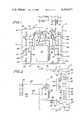
- FIG. 1is a schematic view of a reverse cycle refrigeration heat pump system including a schematic cross sectional elevational view of the outdoor heat exchanger incorporating the present invention
- FIG. 2is a schematic view of the refrigeration system of FIG. 1;
- FIG. 3is a view similar to FIG. 2 showing another embodiment of the invention.
- a heating cycle flow control restricting or expansion means 26connected to the outdoor coil 4 and a cooling expansion means 29 connected to the indoor coil 2, the two expansion means being connected by conduit 28.
- Each of the expansion meanshas associated therewith a bypass line for bypassing the expansion means during operation of the system on one of the cycles.
- the heating expansion means 26is provided with a bypass line 30 including a check valve 31 which permits the flow of condensed refrigerant through the bypass line into the conduit 28 during cooling while the cooling expansion means 29 is provided with a bypass line 32 including a check valve 33 for permitting flow of condensed refrigerant through the bypass line during heating cycle.
- conduit 28 connecting the two expansion means 28 and 29is always part of the high pressure side of the system regardless of whether the system is operating on the cooling or heating cycle and is therefore conveying condensed refrigerant at the pressure of the heat exchanger functioning as the condenser.
- the outdoor heat exchanger 4was of the spirally wound single pass spine fin heat exchange tubing type.
- the various circuits making up the outdoor heat exchangerare formed by cutting the single wound spiral and appropriately connecting the cut ends to form the desired circuits.
- the coilis enclosed in the housing 15 which is substantially rectangular and includes side walls 6 each provided with intake openings 7, a base or drain pan 8 and a top 9 having a discharge opening 11.
- the compressor 10 and reversing valve 14are normally positioned in the outdoor portion 3 generally as shown in FIG. 1 within the spirally wound coil 4.
- the compressor 10discharges relatively hot gaseous refrigerant through discharge line 12 to the four-way reversing valve 14.
- Valve 14selectively operable by suitable means (not shown), reverses refrigerant flow through a portion of the refrigeration system in order to obtain the desired heating or cooling effects.
- hot gaseous refrigerantflows during the cooling cycle operation, illustrated by the solid line arrows, through lines 18 to the outdoor heat exchange coil 4.
- Ambient air passed over the surface of coil 4 by suitable fan means 17effects condensation of the gaseous refrigerant passing through the outdoor coil.
- the liquid refrigerant formed in the heat exchange coil 4flows through line 24, bypass line 31 and line 28 to the indoor expansion means 29 which provides the requisite pressure drop between the indoor and outdoor heat exchange coils in the refrigeration system.
- the refrigerantthereafter flows to the indoor heat exchange coil 2 serving, during the cooling cycle, as an evaporator.
- Refrigerant passing through the indoor coil 2is converted into gaseous refrigerant as it extracts heat from the stream of air flowing over the indoor coil under the influence of suitable fan means (not shown).
- the gaseous refrigerantthereafter passes through line 34 to the reversing valve 14 and thereafter through the compressor suction line 36 to the compressor 10 to complete the refrigerant flow cycle.
- the reversing valve 14may be actuated to place line 12 in communication with the indoor heat exchange coil 2 and line 36 in communication with the outdoor heat exchange coil 4 when it is desired to operate the unit in the heating cycle.
- the dotted line arrowsillustrate the direction of refrigerant flow during the heating cycle.
- heat from the refrigerant flowing in the indoor coilis rejected to the stream of air flowing thereover.
- the rejection of heat from the refrigerantconverts the gaseous refrigerant to liquid refrigerant which flows through bypass check valve 33 to the expansion means 26 to the outdoor coil 4 now functioning as an evaporator.
- the gaseous refrigerant created in the outdoor coil as a result of the heat transferred between the refrigerant and the ambient air passing thereoverflows through lines 18 to reversing valve 14 to the compressor 10.
- ambient outdoor temperaturesmay be such that the coil temperature is below freezing which results in frost or ice build-up on the coil.
- This frost or icehas an insulating effect and blocks air from passing through the coil.
- This build-up of frost or icemust be removed to obtain efficient refrigeration operation.
- defrostingis periodically effected by reversing the system so that hot gaseous refrigerant is directed to the outdoor coil during which time the accumulated frost or ice melts and runs down and off the fins and coils. In certain frost or ice conditions, all of the frost may not clear the heat exchanger coil before the cycle of operation is returned to the heating mode.
- the effectiveness of the system defrostis enhanced since applicant's coil construction serves to pass, during the system defrost cycle, a portion of the relatively hot gaseous refrigerant from the compressor is fed directly to the lower portion of the coil, the area when the heaviest build-up of frost or ice normally occurs.
- Circuit 46includes a first circuit or section 48 arranged above the vertically disposed circuits 40 and a second circuit or section 50 arranged below the vertically disposed circuits 40.
- the circuits 48 and 50are interconnected by line 51 to form the single circuit 46 that is in parallel flow arrangement with the circuits 40 between lines 18 and 24 with inlet and outlet being interchangeable between the upper and lower circuits depending on the direction of refrigerant flow.
- Refrigerant flow through circuit 46is in parallel with circuits 40.
- the hot gaseous refrigerant entering the lower circuit 50effectively melts frost when present thereon.
- the length of the lower circuit 50is such that the temperature of all its surfaces is above freezing so that as the refrigerant condenses and cools in split circuit 46, all of the sub-cooling takes place in the upper circuit 48.
- FIG. 3there is shown another embodiment of the invention wherein similar components of the system are designated with the same reference numerals used in the embodiment of FIG. 1.
- the hot gaseous refrigerant from line 18is directed to two lower defrost circuits rather than the single circuit 46.
- frost buildupis from the base pan up, in some instances it may be necessary to increase the height of the heat exchange area receiving the hot refrigerant.
- the split defrost heat exchange circuit 46includes two circuits 60 and 60' in the upper portion and 62 and 62' in the lower portion.
- hot gaseous refrigerant from the system line 18enters simultaneously the upper portion of both circuits 62 and 62'.
- This arrangementdirects the relatively hot gaseous refrigerant to two points of the lower extremities of outdoor heat exchanger 4 thereby increasing the area being defrosted.
- the hot gaseous refrigerantmay be directed to the lower portions of the defrost circuits as disclosed in the embodiment of FIGS. 1 and 2.
Landscapes
- Engineering & Computer Science (AREA)
- Physics & Mathematics (AREA)
- Mechanical Engineering (AREA)
- Thermal Sciences (AREA)
- General Engineering & Computer Science (AREA)
- Compression-Type Refrigeration Machines With Reversible Cycles (AREA)
- Defrosting Systems (AREA)
Abstract
Description
Claims (5)
Priority Applications (4)
| Application Number | Priority Date | Filing Date | Title |
|---|---|---|---|
| US06/262,250US4359877A (en) | 1981-05-11 | 1981-05-11 | Heat pump coil circuit |
| DE19823216948DE3216948A1 (en) | 1981-05-11 | 1982-05-06 | EXTERNAL HEAT EXCHANGER AND HEAT EXCHANGE DEVICE |
| FR8208216AFR2505465B1 (en) | 1981-05-11 | 1982-05-11 | IMPROVED DEFROST SYSTEM FOR REVERSIBLE CYCLE HEAT PUMPS |
| JP57080846AJPS57192757A (en) | 1981-05-11 | 1982-05-11 | Coil circuit for heat pump |
Applications Claiming Priority (1)
| Application Number | Priority Date | Filing Date | Title |
|---|---|---|---|
| US06/262,250US4359877A (en) | 1981-05-11 | 1981-05-11 | Heat pump coil circuit |
Publications (1)
| Publication Number | Publication Date |
|---|---|
| US4359877Atrue US4359877A (en) | 1982-11-23 |
Family
ID=22996791
Family Applications (1)
| Application Number | Title | Priority Date | Filing Date |
|---|---|---|---|
| US06/262,250Expired - Fee RelatedUS4359877A (en) | 1981-05-11 | 1981-05-11 | Heat pump coil circuit |
Country Status (4)
| Country | Link |
|---|---|
| US (1) | US4359877A (en) |
| JP (1) | JPS57192757A (en) |
| DE (1) | DE3216948A1 (en) |
| FR (1) | FR2505465B1 (en) |
Cited By (4)
| Publication number | Priority date | Publication date | Assignee | Title |
|---|---|---|---|---|
| US4483156A (en)* | 1984-04-27 | 1984-11-20 | The Trane Company | Bi-directional variable subcooler for heat pumps |
| WO2000011383A1 (en)* | 1998-08-25 | 2000-03-02 | Aeroquip Corporation | Manifold assembly |
| US6295828B1 (en)* | 1999-09-08 | 2001-10-02 | Samsung Electronics Co., Ltd. | Apparatus for switching a refrigerant channel of an air conditioner having cooling and warming functions |
| US20090188265A1 (en)* | 2008-01-28 | 2009-07-30 | Lg Electronics Inc. | Air conditioning system |
Families Citing this family (3)
| Publication number | Priority date | Publication date | Assignee | Title |
|---|---|---|---|---|
| DE3315391A1 (en)* | 1983-04-28 | 1984-10-31 | Manfred 5020 Frechen Umbach | DEFROSTING DEVICE FOR SEVERAL REFRIGERATION SYSTEMS |
| DE3333903C2 (en)* | 1983-09-20 | 1986-01-23 | Manfred 5020 Frechen Umbach | Defrosting device for refrigerant evaporator |
| JPH0557602U (en)* | 1991-12-28 | 1993-07-30 | トーソク株式会社 | Micrometer |
Citations (6)
| Publication number | Priority date | Publication date | Assignee | Title |
|---|---|---|---|---|
| US2806674A (en)* | 1954-09-02 | 1957-09-17 | Westinghouse Electric Corp | Heat pumps |
| US4057977A (en)* | 1976-10-06 | 1977-11-15 | General Electric Company | Reverse cycle heat pump circuit |
| US4171622A (en)* | 1976-07-29 | 1979-10-23 | Matsushita Electric Industrial Co., Limited | Heat pump including auxiliary outdoor heat exchanger acting as defroster and sub-cooler |
| US4182133A (en)* | 1978-08-02 | 1980-01-08 | Carrier Corporation | Humidity control for a refrigeration system |
| US4240269A (en)* | 1979-05-29 | 1980-12-23 | Carrier Corporation | Heat pump system |
| US4313313A (en)* | 1980-01-17 | 1982-02-02 | Carrier Corporation | Apparatus and method for defrosting a heat exchanger of a refrigeration circuit |
Family Cites Families (2)
| Publication number | Priority date | Publication date | Assignee | Title |
|---|---|---|---|---|
| US3142970A (en)* | 1963-02-11 | 1964-08-04 | Carrier Corp | Coil apparatus |
| US3534806A (en)* | 1968-08-01 | 1970-10-20 | K E T G Corp | Air conditioning method and system |
- 1981
- 1981-05-11USUS06/262,250patent/US4359877A/ennot_activeExpired - Fee Related
- 1982
- 1982-05-06DEDE19823216948patent/DE3216948A1/ennot_activeWithdrawn
- 1982-05-11JPJP57080846Apatent/JPS57192757A/enactivePending
- 1982-05-11FRFR8208216Apatent/FR2505465B1/ennot_activeExpired
Patent Citations (6)
| Publication number | Priority date | Publication date | Assignee | Title |
|---|---|---|---|---|
| US2806674A (en)* | 1954-09-02 | 1957-09-17 | Westinghouse Electric Corp | Heat pumps |
| US4171622A (en)* | 1976-07-29 | 1979-10-23 | Matsushita Electric Industrial Co., Limited | Heat pump including auxiliary outdoor heat exchanger acting as defroster and sub-cooler |
| US4057977A (en)* | 1976-10-06 | 1977-11-15 | General Electric Company | Reverse cycle heat pump circuit |
| US4182133A (en)* | 1978-08-02 | 1980-01-08 | Carrier Corporation | Humidity control for a refrigeration system |
| US4240269A (en)* | 1979-05-29 | 1980-12-23 | Carrier Corporation | Heat pump system |
| US4313313A (en)* | 1980-01-17 | 1982-02-02 | Carrier Corporation | Apparatus and method for defrosting a heat exchanger of a refrigeration circuit |
Cited By (6)
| Publication number | Priority date | Publication date | Assignee | Title |
|---|---|---|---|---|
| US4483156A (en)* | 1984-04-27 | 1984-11-20 | The Trane Company | Bi-directional variable subcooler for heat pumps |
| WO2000011383A1 (en)* | 1998-08-25 | 2000-03-02 | Aeroquip Corporation | Manifold assembly |
| US6363965B1 (en)* | 1998-08-25 | 2002-04-02 | Eaton Aeroquip Inc. | Manifold assembly |
| US6295828B1 (en)* | 1999-09-08 | 2001-10-02 | Samsung Electronics Co., Ltd. | Apparatus for switching a refrigerant channel of an air conditioner having cooling and warming functions |
| US20090188265A1 (en)* | 2008-01-28 | 2009-07-30 | Lg Electronics Inc. | Air conditioning system |
| US7918098B2 (en)* | 2008-01-28 | 2011-04-05 | Lg Electronics Inc. | Air conditioning system |
Also Published As
| Publication number | Publication date |
|---|---|
| DE3216948A1 (en) | 1982-12-02 |
| JPS57192757A (en) | 1982-11-26 |
| FR2505465A1 (en) | 1982-11-12 |
| FR2505465B1 (en) | 1986-04-25 |
Similar Documents
| Publication | Publication Date | Title |
|---|---|---|
| CN1605821B (en) | Evaporator for refrigerated merchandisers | |
| US4565070A (en) | Apparatus and method for defrosting a heat exchanger in a refrigeration circuit | |
| US4285205A (en) | Refrigerant sub-cooling | |
| US4554968A (en) | Wrapped fin heat exchanger circuiting | |
| US4936107A (en) | External heat exchange unit with plurality of heat exchanger elements and fan devices and method for controlling fan devices | |
| US4171622A (en) | Heat pump including auxiliary outdoor heat exchanger acting as defroster and sub-cooler | |
| US5275008A (en) | Air conditioner with auxillary condenser defrost | |
| US20080141708A1 (en) | Space-Saving Multichannel Heat Exchanger | |
| US3142970A (en) | Coil apparatus | |
| US7216494B2 (en) | Supermarket refrigeration system and associated methods | |
| US4407137A (en) | Fast defrost heat exchanger | |
| US4976116A (en) | Cold-air generating device | |
| EP0249472A2 (en) | Refrigeration system with hot gas pre-cooler | |
| CA1189703A (en) | Climatic control system | |
| JPH07180930A (en) | Liquid receiver integrated type refrigerant condenser | |
| US3545224A (en) | Heat pump apparatus | |
| US4302945A (en) | Method for defrosting a refrigeration system | |
| US4305417A (en) | Rotationally indexing valve | |
| US4359877A (en) | Heat pump coil circuit | |
| US3313123A (en) | Condensate removal apparatus | |
| US5157935A (en) | Hot gas defrost system for refrigeration systems and apparatus therefor | |
| CA1121168A (en) | Refrigeration circuit defrost system, method and components | |
| US3195321A (en) | Refrigeration system including defrosting means | |
| JP2000205735A (en) | refrigerator | |
| US20120114474A1 (en) | Fin array for use in a centrifugal fan |
Legal Events
| Date | Code | Title | Description |
|---|---|---|---|
| AS | Assignment | Owner name:GENERAL ELECTRIC COMPANY, A CORP. OF NY. Free format text:ASSIGNMENT OF ASSIGNORS INTEREST.;ASSIGNOR:COYNE GERARD G.;REEL/FRAME:003888/0404 Effective date:19810423 | |
| AS | Assignment | Owner name:TRANE CAC, INC., LA CROSSE, WI, A CORP. OF DE Free format text:ASSIGNMENT OF ASSIGNORS INTEREST.;ASSIGNOR:GENERAL ELECTRIC COMPANY A NY CORP.;REEL/FRAME:004053/0022 Effective date:19820915 | |
| AS | Assignment | Owner name:AMERICAN STANDARD INC., A CORP OF DE Free format text:MERGER;ASSIGNORS:TRANE COMPANY, THE;A-S SALEM INC., A CORP. OF DE (MERGED INTO);REEL/FRAME:004372/0349 Effective date:19841226 | |
| AS | Assignment | Owner name:TRANE COMPANY THE A DE CORP. Free format text:MERGER;ASSIGNOR:TRANE CAC, INC., A CORP OF DE;REEL/FRAME:004432/0755 Effective date:19831222 Owner name:TRANE COMPANY THE A WI CORP Free format text:MERGER;ASSIGNOR:TRANE CAC, INC. A DE CORP. (INTO);REEL/FRAME:004432/0778 Effective date:19831222 Owner name:A-S CAPITAL INC., A CORP OF DE Free format text:MERGER;ASSIGNOR:TRANE COMPANY THE A WI CORP;REEL/FRAME:004432/0765 Effective date:19840224 | |
| AS | Assignment | Owner name:A-S CAPITAL INC. Free format text:MERGER;ASSIGNOR:TRANE COMPANY THE;REEL/FRAME:004476/0376 Effective date:19840224 | |
| MAFP | Maintenance fee payment | Free format text:PAYMENT OF MAINTENANCE FEE, 4TH YEAR, PL 96-517 (ORIGINAL EVENT CODE: M170); ENTITY STATUS OF PATENT OWNER: LARGE ENTITY Year of fee payment:4 | |
| AS | Assignment | Owner name:TRANE COMPANY THE, A COMPANY OF WISCONSIN Free format text:MERGER;ASSIGNORS:TRANE COMPANY AND TRANE CAC, INC.;TRANE CAC, INC.;REEL/FRAME:004508/0687 Effective date:19831222 | |
| AS | Assignment | Owner name:BANKERS TRUST COMPANY Free format text:SECURITY INTEREST;ASSIGNOR:AMERICAN STANDARD INC., A DE. CORP.,;REEL/FRAME:004905/0035 Effective date:19880624 Owner name:BANKERS TRUST COMPANY, 4 ALBANY STREET, 9TH FLOOR, Free format text:SECURITY INTEREST;ASSIGNOR:TRANE AIR CONDITIONING COMPANY, A DE CORP.;REEL/FRAME:004905/0213 Effective date:19880624 Owner name:BANKERS TRUST COMPANY, NEW YORK Free format text:SECURITY INTEREST;ASSIGNOR:TRANE AIR CONDITIONING COMPANY, A DE CORP.;REEL/FRAME:004905/0213 Effective date:19880624 | |
| MAFP | Maintenance fee payment | Free format text:PAYMENT OF MAINTENANCE FEE, 8TH YEAR, PL 96-517 (ORIGINAL EVENT CODE: M171); ENTITY STATUS OF PATENT OWNER: LARGE ENTITY Year of fee payment:8 | |
| AS | Assignment | Owner name:CHEMICAL BANK, AS COLLATERAL AGENT, NEW YORK Free format text:ASSIGNMENT OF SECURITY INTEREST;ASSIGNOR:BANKERS TRUST COMPANY, AS COLLATERAL TRUSTEE;REEL/FRAME:006565/0753 Effective date:19930601 Owner name:CHEMICAL BANK, AS COLLATERAL AGENT, NEW YORK Free format text:ASSIGNMENT OF ASSIGNORS INTEREST;ASSIGNOR:AMERICAN STANDARD INC.;REEL/FRAME:006566/0170 Effective date:19930601 | |
| FEPP | Fee payment procedure | Free format text:MAINTENANCE FEE REMINDER MAILED (ORIGINAL EVENT CODE: REM.); ENTITY STATUS OF PATENT OWNER: LARGE ENTITY | |
| LAPS | Lapse for failure to pay maintenance fees | ||
| FP | Lapsed due to failure to pay maintenance fee | Effective date:19941123 | |
| AS | Assignment | Owner name:AMERICAN STANDARD, INC., NEW JERSEY Free format text:RELEASE OF SECURITY INTEREST (RE-RECORD TO CORRECT DUPLICATES SUBMITTED BY CUSTOMER. THE NEW SCHEDULE CHANGES THE TOTAL NUMBER OF PROPERTY NUMBERS INVOLVED FROM 1133 TO 794. THIS RELEASE OF SECURITY INTEREST WAS PREVIOUSLY RECORDED AT REEL 8869, FRAME 0001.);ASSIGNOR:CHASE MANHATTAN BANK, THE (FORMERLY KNOWN AS CHEMICAL BANK);REEL/FRAME:009123/0300 Effective date:19970801 | |
| AS | Assignment | Owner name:AMERICAN STANDARD, INC., NEW JERSEY Free format text:RELEASE OF SECURITY INTEREST;ASSIGNOR:CHASE MANHATTAN BANK, THE (FORMERLY KNOWN AS CHEMICAL BANK);REEL/FRAME:008869/0001 Effective date:19970801 | |
| AS | Assignment | Owner name:AMERICAN STANDARD INTERNATIONAL INC., NEW YORK Free format text:NOTICE OF ASSIGNMENT;ASSIGNOR:AMERICAN STANDARD INC., A CORPORATION OF DELAWARE;REEL/FRAME:011474/0650 Effective date:20010104 | |
| STCH | Information on status: patent discontinuation | Free format text:PATENT EXPIRED DUE TO NONPAYMENT OF MAINTENANCE FEES UNDER 37 CFR 1.362 |