US4357672A - Distance ranging apparatus and method - Google Patents
Distance ranging apparatus and methodDownload PDFInfo
- Publication number
- US4357672A US4357672AUS06/173,723US17372380AUS4357672AUS 4357672 AUS4357672 AUS 4357672AUS 17372380 AUS17372380 AUS 17372380AUS 4357672 AUS4357672 AUS 4357672A
- Authority
- US
- United States
- Prior art keywords
- microprocessor system
- wave energy
- movable element
- count
- counts
- Prior art date
- Legal status (The legal status is an assumption and is not a legal conclusion. Google has not performed a legal analysis and makes no representation as to the accuracy of the status listed.)
- Expired - Lifetime
Links
- 238000000034methodMethods0.000titleclaimsabstractdescription18
- 230000006870functionEffects0.000claimsdescription12
- 230000001902propagating effectEffects0.000claimsdescription8
- 241001422033ThestylusSpecies0.000description8
- 238000010586diagramMethods0.000description7
- 230000008901benefitEffects0.000description5
- 229910003460diamondInorganic materials0.000description3
- 239000010432diamondSubstances0.000description3
- 230000006872improvementEffects0.000description2
- 238000004519manufacturing processMethods0.000description2
- 230000035939shockEffects0.000description2
- 230000000903blocking effectEffects0.000description1
- 230000001419dependent effectEffects0.000description1
- 230000000694effectsEffects0.000description1
- 230000005611electricityEffects0.000description1
- 230000014509gene expressionEffects0.000description1
- 239000011521glassSubstances0.000description1
- 230000001976improved effectEffects0.000description1
- 230000009191jumpingEffects0.000description1
- 239000002184metalSubstances0.000description1
- 239000004033plasticSubstances0.000description1
- 239000002985plastic filmSubstances0.000description1
- 230000004044responseEffects0.000description1
- 238000004513sizingMethods0.000description1
- 239000007787solidSubstances0.000description1
- 230000008093supporting effectEffects0.000description1
- 230000003319supportive effectEffects0.000description1
- 230000007704transitionEffects0.000description1
- 230000001960triggered effectEffects0.000description1
Images

Classifications
- G—PHYSICS
- G01—MEASURING; TESTING
- G01S—RADIO DIRECTION-FINDING; RADIO NAVIGATION; DETERMINING DISTANCE OR VELOCITY BY USE OF RADIO WAVES; LOCATING OR PRESENCE-DETECTING BY USE OF THE REFLECTION OR RERADIATION OF RADIO WAVES; ANALOGOUS ARRANGEMENTS USING OTHER WAVES
- G01S15/00—Systems using the reflection or reradiation of acoustic waves, e.g. sonar systems
- G01S15/02—Systems using the reflection or reradiation of acoustic waves, e.g. sonar systems using reflection of acoustic waves
- G01S15/06—Systems determining the position data of a target
- G01S15/46—Indirect determination of position data
- G—PHYSICS
- G01—MEASURING; TESTING
- G01S—RADIO DIRECTION-FINDING; RADIO NAVIGATION; DETERMINING DISTANCE OR VELOCITY BY USE OF RADIO WAVES; LOCATING OR PRESENCE-DETECTING BY USE OF THE REFLECTION OR RERADIATION OF RADIO WAVES; ANALOGOUS ARRANGEMENTS USING OTHER WAVES
- G01S15/00—Systems using the reflection or reradiation of acoustic waves, e.g. sonar systems
- G01S15/88—Sonar systems specially adapted for specific applications
Definitions
- This inventionrelates to improvements in distance ranging apparatus and, more particularly, to a distance ranging technique and apparatus, such as a graphical digitizer, which employs a microprocessor.
- ranging systemswhich employ wave energy, preferably acoustic wave energy or other wave energy which is of the nature of a mechanical disturbance, in the determination of the distance between an object and a reference location by determining the transit time of the wave energy traveling between the object and the reference.
- wave energypreferably acoustic wave energy or other wave energy which is of the nature of a mechanical disturbance
- One type of equipment that employs this principleis the graphical data digitizer that is conventionally used to input graphical coordinate information, or the like, to a companion system.
- wave energyis typically passed between a movable element (such as a stylus or cursor) and one or more transducers located at fixed reference locations.
- the transit time of the wave energy traveling between the movable element and the reference locationsis used in determining the position of the movable element, typically in terms of digital coordinates.
- graphical data digitizersThere are many types of commerically available graphical data digitizers, and these operate in a variety of ways. For example, the type of graphical data digitizer manufactured and sold by applicants' assignee, Science Accessories Corp., measures the transit time of acoustic wave energy propagating through air. Other graphical data digitizers measure the transit time of wave energy through a solid data tablet, or through wires, etc. Regardless of the transition medium employed, a necessary part of these systems is timing circuitry for timing the travel of wave energy between the movable element and one or more reference locations or positions.
- clock pulsesare generated at a predetermined rate and circuitry is used to initiate a count of clock pulses when the wave energy is emitted from the movable element (or the reference, depending on the mode of operation) and subsequently to terminate the count when the wave energy arrives at the reference location (or the movable element).
- the circuitry for generating this timingcan tend to be expensive and to increase the manufacturing cost of a graphical data digitizer equipment. The cost of this circuitry can be particularly significant when attempting to manufacture a relatively low cost system, for example, a graphical data digitizer system that would be affordable by the public at large for use in conjunction with personal computers.
- Another type of equipment which employs a sonic ranging principleis an automatically focusing camera.
- the present inventionis directed to an apparatus and method for determining the distance between an object and a reference position.
- a microprocessor systemis provided, and includes a central processor unit, a memory, and a timing circuit for producing timing pulses which determine the rate at which said microprocessor system performs individual instructions.
- means controlled by the microprocessor systemare provided for generating propagating wave energy. Further means are provided for detecting the wave energy after it has passed between the object and the reference position.
- the microprocessor systemis adapted to generate and store a count that depends upon the number of instruction cycles that the microprocessor system performs during a time interval that is a function of the travel time of said wave energy traveling between the object and said reference position. Assuming the propagation speed is known (e.g. through air), the count will be indicative of the distance between the object and the reference position.
- a graphical data digitizing devicefor determining the position of a movable element with respect to first and second reference locations.
- the means controlled by the microprocessor systemis used to generate pulses of acoustic wave energy at the movable element.
- First and second spaced acoustic receiversare coupled to the microprocessor system.
- the microprocessor systemis adapted to initiate a first count of instruction cycles of the microprocessor system upon generation of a pulse of acoustic wave energy, and to terminate said first count when the acoustic wave energy is received at the first acoustic receiver.
- the microprocessor systemis adapted to initiate a second count of its instruction cycles when the pulse of acoustic wave energy is generated and to terminate said second count when the acoustic wave energy is received at the second receiver.
- the terminated first and second countsare stored and are indicative of the distance between the movable element and the first and second receivers, respectively.
- the acoustic receiversare mounted with their axes parallel, and each receiver has a generally circular receptivity pattern.
- the present inventionhas advantage for use in conjunction with apparatus which performs sonic ranging through air.
- propagation through airis slow enough that a count of microprocessor system instruction cycles is at a high enough rate to provide a substantial number of counts per unit distance traveled by the sound wave energy. Since, under present technology, the operating frequency of existing economical microprocessor systems is limited, the relatively slow propagation speed of sound through air is an advantage in obtaining adequate resolution with economically available operating frequencies.
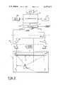
- FIG. 1is a block diagram of a graphical data digitizing device in accordance with the invention and which can be used to practice the method of the invention.
- FIG. 2is a front elevational perspective view of the housing of the embodiment of FIG. 1, showing the microphones of the embodiment of FIG. 1.
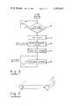
- FIG. 3is a flow diagram of the routine used to program the microprocessor system of the FIG. 1 embodiment.
- FIG. 4is a flow diagram of the "interrupt" portion of the routine of FIG. 3.
- a data spaceis generally defined by the surface area just above a generally flat surface 11, although it will become clear that the data space in accordance with the invention is not necessarily restricted and that the surface is supportive only and performs no active function in the operation of the invention.
- the surface 11may be a glass or plastic sheet for supporting documents for writing purposes and sufficiently transparent to enable tracings to be made, or it may be the surface of a display device upon which specific points, lines or areas are to be precisely located.
- a movable element or "stylus" 12preferably in cartridge form, is movable over the surface 11 and has a tip 13 which may, for example, be a conventional ball point pen cartridge.
- the tip of the stylusalso includes an electrode pair which has a gap for producing an electrical discharge in the form of a spark.
- the sparkis constituted by a sudden discontinuous discharge of electricity through air and produces a fast rise time sound pulse or wave radiating from the point of discharge.
- the spark-generating stylusis well known in the art and is described in further detail, for example, in the U.S. Pat. No. 3,838,212.
- Other techniquescan alternatively be used for generating pulses of acoustic energy, for example by employing a piezoelectric transducer.
- the stylus sparkswhich may be individual or at regular intervals, are triggered by a spark trigger circuit 41 which is also disclosed in the U.S. Pat. No. 3,838,212.
- the shock wave created by the spark at the tip of stylus 12propagates through the atmosphere until contacting transducers A and B which, in the present embodiment, are electret button microphones each having a substantially circular receptivity pattern.
- the microphonesare mounted along a straight line, a distance c apart, in an elongated, hollow, generally rectangular housing 90, typically formed of metal or plastic.
- the bar-shaped housing 90which also preferably houses all of the electronics set forth in FIG. 1, is also illustrated in FIG. 2, which shows a front view of the microphones A and B.
- the microphoneswhich may be, for example "Realistic” brand lapel microphones sold by Tandy Corp., have parallel axes in the present embodiment.
- the microphonespreferably have a circular receptivity pattern and a virtual center which is helpful in obtaining more accurate digitalization.
- the outputs of microphones A and Bare coupled via amplifiers 21 and 31, respectively, to logic circuitry 95 which is, in turn, coupled to interface 140 of a microprocessor system 200.
- the microprocessor system 200includes a microprocessor central processing unit 100, which may be any suitable unit for example a model Z80 manufactured by Zilog Corp. of Cupertino, Calif. As is conventional in the microprocessor art, the microprocessor central processing unit 100 operates in conjunction with other components of the microprocessor system 200, viz., a read-only memory (ROM) 110 in which the program is stored, a random access memory (RAM) 120, and a timing circuit 130 which includes the basic system clock.
- ROMread-only memory
- RAMrandom access memory
- the timing circuit 130may be any suitable microprocessor timing generator as is disclosed, for example, in the "TRS-80 Microcomputer Technical Reference Handbook" of Tandy Corp. In one form of the present invention, a basic clocking frequency of about 2 MHz was employed.
- the interface 140is preferably a standard parallel input/output interface, for example, a "PIO” interface manufactured by Zilog Corp. for use in conjunction with the Zilog Model Z-80 microprocessor.
- a "pen switch" in the tip 13 of stylus 12is coupled to the microprocessor system via interface 140.
- the logic circuitry 95includes AND gates 96 and 97 and an OR gate 98.
- the AND gate 96receives as one input thereof the output of microphone A via amplifier 21 and as its other input a signal designated "flag A" which is received from microprocessor 100 via interface 140.
- the AND gate 97receives as one input the output of microphone B via amplifier 31, and receives as its other input a signal designated "flag B” which is received from microprocessor 100 via interface 140.
- the outputs of AND gates 96 and 97are coupled to the inputs of OR gate 98 whose output is coupled to an "interrupt" input of microprocessor 100 via interface 140.
- a companion systemwhich is typically a computer but may be any companion equipment which utilizes the digital information produced by the disclosed apparatus, is coupled to microprocessor via interface 140 (or via another interface, if desired). Also, suitable power supplies (not shown) are provided to the apparatus, as is conventional.
- FIG. 1 apparatusOperation of the FIG. 1 apparatus is controlled by the microprocessor system 200, as will be described in detail hereinbelow in conjunction with the microprocessor program flow diagram. Briefly, however, operation of the apparatus is as follows: The distances between the stylus tip and the microphones A and B can be determined from the time duration of transit of acoustic energy between the stylus tip and each microphone. When a spark is generated at the stylus tip, the microprocessor immediately begins keeping track of the time it takes for the sound wave front to reach the microphones. This is done by counting instruction cycles of the microprocessor system, and no additonal clock or scaler is necessary, as in conventional graphical data digitizers. When the sound energy reaches a selected one of the microphones, the count is terminated. The procedure is then repeated using the other microphone.
- the spark shock waveproduces a fast rise time electrical impulse upon impinging on the microphone surface, and the band pass amplifiers 21 and 31 allow only the fast rise time portion of the electrical pulse to pass while blocking out noise signals outside the band.
- the amplifiersinclude threshold discriminators which provide an output pulse with steep leading edges in response to the input thereto exceeding a predetermined level.
- the range determinationsare, of course, dependent upon the speed of sound in air which is essentially a known quantity. Since the velocity of sound in air varies with temperature, appropriate velocity compensation techniques can be employed, as known in the art, to generate suitable correction signals.
- FIG. 1assume that microphone A is the origin and that the rectangular coordinates of the stylus tip are represented by x and y. If the distance between microphone centers is designated c and the distance between the stylus tip and the microphones A and B are respectively designated by a and b, the expressions for x and y are:
- the dashed lines 15 and 16indicate the bounds of the area within which the stylus position is to be determined in this embodiment. Determinations outside lines 15 and 16 (e.g. with negative values of x resulting from positions to the left of line 15) can be obtained, but excessively obtuse angles tend to introduce error due to number sizing.
- FIGS. 3 and 4there is shown a flow diagram in accordance with which the microprocessor system is programmed to carry out the functions described herein.
- the flow diagram of FIG. 3is entered when a command is made, via the computer or companion system (referenced in FIG. 1) to which the digital graphical information is to be fed, requesting the next piece of digitized graphical data.
- an operator-controlled switch(not shown) could be used to initiate the "digitize" routine of FIG. 3.
- inquiryis made (decision diamond 311) as to whether or not the "pen down" switch of stylus 12 is closed.
- a contact switch at the end of the penis conveniently used to indicate a point or series of points to be digitized by application of writing pressure.
- the diamond 311is reentered and loop 312 is continued while waiting for the pen-down switch to be closed.
- block 313is entered, this block representing the setting of a flag designated "flag A”.
- a counteris then initialized at zero, as represented by the block 314.
- the block 315is then entered and a pulse command is issued to the spark trigger 41 (FIG. 1).
- the counterwhich has been initialized at zero, is then incremented (block 316), and continues to be incremented, as indicated by the loop 317.
- the countercan be incremented by using a series of "increment counter” instructions in the microprocessor program, in which case the count will be equal to the number of instruction cycles of the microprocessor system that occurred after issuance of the pulse command.
- the loop 317could be implemented by following an "increment counter” instruction with a “jump back” instruction (i.e., jumping back to the "increment counter” instruction).
- the digitizer resolutionis in terms of the count rate, so it is advantageous to have the highest possible count rate (for example, by implementing the loop 317 using a series of "increment counter” instructions).
- the microprocessoris of the type which records the instruction from which an interrupt is implemented, it will be understood that one can alternatively obtain a maximized count of instruction cycles even when using a "jump back" instruction (which saves program space, as compared to a long series of "increment counter” instructions).
- the actual number of instruction cyclescan be determined from a knowledge of whether an interrupt was effected from the "increment counter” instruction or the "jump back” instruction. In such case the number of instruction cycles will be either twice the stored count (in cases where the interrupt was effected after an "increment counter” instruction) or twice the stored count plus one (where an interrupt was effected after the "jump back" instruction).
- the loop 317continues until an "interrupt” occurs (output of OR gate 98 in FIG. 1) by virtue of sound wave energy being received at an acoustic receiver (A and/or B), and depending upon which flag is set.
- flag AWhen flag A is set, AND gate 96 is enabled and an output from receiver A will cause an interrupt via AND gate 96 and OR gate 98.
- flag BWhen flag B is set, AND gate 97 is enabled and an output from receiver B will cause an interrupt via AND gate 97 and OR gate 98.
- the "interrupt" routineis then entered, the flow diagram for this routine being illustrated in FIG. 4. When an interrupt occurs, a test is made to see whether flag A or flag B is set, as represented by the demand 411. If flag A is set, block 412 is entered and the contents of the counter are stored in location A. Flag A is then reset (block 413) and flag B is set (block 414). Return is then made to block 314 of the "digitize" routine.
- Block 422can then be entered, and the (x,y) coordinates of the movable element (stylus or cursor) position are computed in accordance with relationships (3) and (4), set forth above.
- the routineis then exited and, typically, return is made to a predetermined point in the program of the computer or companion equipment to which the digitizer is coupled. It will be understood that, if desired, the computations indicated as being performed by block 422 could alternatively be performed by the companion computer or companion equipment.
- the present inventionhas particular advantage for use in conjunction with apparatus which performs sonic ranging through air. Propagation through air is slow enough that a count of microprocessor system instruction cycles is at a high enough rate to provide a substantial number of counts per unit distance traveled by the sound wave energy. Since, under present technology, the operating frequency of existing economical microprocessor systems is limited, the relatively slow propagation speed of sound through air is an advantage in obtaining adequate resolution with economically available operating frequencies.
Landscapes
- Engineering & Computer Science (AREA)
- Radar, Positioning & Navigation (AREA)
- Remote Sensing (AREA)
- Physics & Mathematics (AREA)
- Acoustics & Sound (AREA)
- Computer Networks & Wireless Communication (AREA)
- General Physics & Mathematics (AREA)
- Measurement Of Velocity Or Position Using Acoustic Or Ultrasonic Waves (AREA)
Abstract
Description
x.sup.2 +y.sup.2 =a.sup.2 (1)
(c-x).sup.2 +y.sup.2 =b.sup.2 (2)
Claims (33)
Priority Applications (3)
| Application Number | Priority Date | Filing Date | Title |
|---|---|---|---|
| US06/173,723US4357672A (en) | 1980-07-30 | 1980-07-30 | Distance ranging apparatus and method |
| EP81902172AEP0057204A1 (en) | 1980-07-30 | 1981-07-27 | Distance ranging apparatus and method |
| PCT/US1981/000995WO1982000526A1 (en) | 1980-07-30 | 1981-07-27 | Distance ranging apparatus and method |
Applications Claiming Priority (1)
| Application Number | Priority Date | Filing Date | Title |
|---|---|---|---|
| US06/173,723US4357672A (en) | 1980-07-30 | 1980-07-30 | Distance ranging apparatus and method |
Publications (1)
| Publication Number | Publication Date |
|---|---|
| US4357672Atrue US4357672A (en) | 1982-11-02 |
Family
ID=22633217
Family Applications (1)
| Application Number | Title | Priority Date | Filing Date |
|---|---|---|---|
| US06/173,723Expired - LifetimeUS4357672A (en) | 1980-07-30 | 1980-07-30 | Distance ranging apparatus and method |
Country Status (3)
| Country | Link |
|---|---|
| US (1) | US4357672A (en) |
| EP (1) | EP0057204A1 (en) |
| WO (1) | WO1982000526A1 (en) |
Cited By (37)
| Publication number | Priority date | Publication date | Assignee | Title |
|---|---|---|---|---|
| US4578768A (en)* | 1984-04-06 | 1986-03-25 | Racine Marsh V | Computer aided coordinate digitizing system |
| US4630226A (en)* | 1983-09-19 | 1986-12-16 | Nissan Motor Company, Limited | Ultra-sonic distance sensor system and method with correction feature for sensor value |
| US4658385A (en)* | 1984-05-25 | 1987-04-14 | Casio Computer Co., Ltd. | Obstacle detection system |
| US4661039A (en)* | 1983-10-20 | 1987-04-28 | Donaldson Company | Flexible-frame robot |
| US4811250A (en)* | 1986-05-02 | 1989-03-07 | Applied Power Inc. | Deviation measurement system |
| US4912663A (en)* | 1988-03-02 | 1990-03-27 | Westinghouse Electric Corp. | Sonic digitizer coil measurement system |
| US4973800A (en)* | 1988-12-15 | 1990-11-27 | Science Accessories Corp. | Apparatus for digitizing positions on a transparency |
| US4991148A (en)* | 1989-09-26 | 1991-02-05 | Gilchrist Ian R | Acoustic digitizing system |
| US5043950A (en)* | 1990-01-19 | 1991-08-27 | Science Accessories Corp. | Apparatus and method for distance determination |
| US5047960A (en)* | 1989-01-04 | 1991-09-10 | Sloan Scott K | Apparatus and method to automate data entry into an application program |
| US5050134A (en)* | 1990-01-19 | 1991-09-17 | Science Accessories Corp. | Position determining apparatus |
| US5054005A (en)* | 1990-03-16 | 1991-10-01 | Science Accessories Corp. | Apparatus and method for determining travel time of acoustic energy |
| US5056783A (en)* | 1989-10-18 | 1991-10-15 | Batronics, Inc. | Sports implement swing analyzer |
| US5142506A (en)* | 1990-10-22 | 1992-08-25 | Logitech, Inc. | Ultrasonic position locating method and apparatus therefor |
| US5235511A (en)* | 1988-06-09 | 1993-08-10 | Spectra-Physics, Inc. | Method for automatic depth control for earth moving and grading |
| US5280457A (en)* | 1992-07-31 | 1994-01-18 | The Administrators Of The Tulane Educational Fund | Position detecting system and method |
| US5308936A (en)* | 1992-08-26 | 1994-05-03 | Mark S. Knighton | Ultrasonic pen-type data input device |
| US5379269A (en)* | 1993-01-13 | 1995-01-03 | Science Accessories Corp. | Position determining apparatus |
| US5491706A (en)* | 1993-04-07 | 1996-02-13 | Sharp Kabushiki Kaisha | Display-integrated type tablet device capable of detecting correct coordinates at a tip end of a detection pen by detecting external noise |
| US5517579A (en)* | 1994-02-04 | 1996-05-14 | Baron R & D Ltd. | Handwritting input apparatus for handwritting recognition using more than one sensing technique |
| US5652593A (en)* | 1994-09-29 | 1997-07-29 | Von Schrader Company | Method and apparatus for guiding a machine |
| US5920288A (en)* | 1995-06-07 | 1999-07-06 | Parkervision, Inc. | Tracking system and method for controlling the field of view of a camera |
| US6067080A (en)* | 1997-02-21 | 2000-05-23 | Electronics For Imaging | Retrofittable apparatus for converting a substantially planar surface into an electronic data capture device |
| US6100877A (en)* | 1998-05-14 | 2000-08-08 | Virtual Ink, Corp. | Method for calibrating a transcription system |
| US6104387A (en)* | 1997-05-14 | 2000-08-15 | Virtual Ink Corporation | Transcription system |
| US6111565A (en)* | 1998-05-14 | 2000-08-29 | Virtual Ink Corp. | Stylus for use with transcription system |
| US6124847A (en)* | 1998-05-14 | 2000-09-26 | Virtual Ink, Corp. | Collapsible detector assembly |
| US6147681A (en)* | 1998-05-14 | 2000-11-14 | Virtual Ink, Corp. | Detector for use in a transcription system |
| US6177927B1 (en) | 1998-05-14 | 2001-01-23 | Virtual Ink Corp. | Transcription system kit |
| US6191778B1 (en) | 1998-05-14 | 2001-02-20 | Virtual Ink Corp. | Transcription system kit for forming composite images |
| US6211863B1 (en) | 1998-05-14 | 2001-04-03 | Virtual Ink. Corp. | Method and software for enabling use of transcription system as a mouse |
| US6292177B1 (en) | 1997-03-05 | 2001-09-18 | Tidenet, Inc. | Marking device for electronic presentation board |
| US6310615B1 (en) | 1998-05-14 | 2001-10-30 | Virtual Ink Corporation | Dual mode eraser |
| US6326565B1 (en) | 1997-02-28 | 2001-12-04 | Electronics For Imaging, Inc. | Marking device for electronic presentation board |
| US20020054026A1 (en)* | 2000-04-17 | 2002-05-09 | Bradley Stevenson | Synchronized transmission of recorded writing data with audio |
| US7050509B2 (en) | 1997-04-22 | 2006-05-23 | Silicon Laboratories Inc. | Digital isolation system with hybrid circuit in ADC calibration loop |
| US20080059114A1 (en)* | 2004-05-26 | 2008-03-06 | Philippe Coperet | Device and Method for the Dimensional Characterization of a Cylindrical Object |
Families Citing this family (4)
| Publication number | Priority date | Publication date | Assignee | Title |
|---|---|---|---|---|
| US4578674A (en)* | 1983-04-20 | 1986-03-25 | International Business Machines Corporation | Method and apparatus for wireless cursor position control |
| NL8500088A (en)* | 1985-01-16 | 1986-08-18 | Lely Nv C Van Der | DEVICE FOR AUTOMATIC MILKING OF AN ANIMAL. |
| NL8502039A (en)* | 1985-07-16 | 1987-02-16 | Nedap Nv | DEVICE FOR AUTOMATIC APPLICATION OF A MILK. |
| US5082276A (en)* | 1991-03-04 | 1992-01-21 | Stevens Douglas W | Distance measuring golf putting apparatus |
Citations (11)
| Publication number | Priority date | Publication date | Assignee | Title |
|---|---|---|---|---|
| US3757285A (en)* | 1971-07-22 | 1973-09-04 | R Ferre | Acoustic range measuring device |
| US4012588A (en)* | 1975-08-29 | 1977-03-15 | Science Accessories Corporation | Position determining apparatus and transducer therefor |
| US4037189A (en)* | 1975-10-20 | 1977-07-19 | Western Gear Corporation | Method and apparatus for determining the profile of an underwater pipeline |
| US4038530A (en)* | 1975-07-24 | 1977-07-26 | Oki Electric Industry Company, Ltd. | Hybrid computer for displaying sound rays of a sonar system |
| US4049954A (en)* | 1975-04-22 | 1977-09-20 | Commissariat A L'energie Atomique | Device for accurate measurement of the dimensions of an object by ultrasonic waves |
| US4113382A (en)* | 1975-12-12 | 1978-09-12 | Karl Vockenhuber | Method of and system for measuring distances |
| US4118782A (en)* | 1977-03-24 | 1978-10-03 | The United States Of America As Represented By The Secretary Of The Navy | Digital sound velocity calculator |
| US4136394A (en)* | 1977-09-23 | 1979-01-23 | Joseph Jones | Golf yardage indicator system |
| US4238844A (en)* | 1978-02-28 | 1980-12-09 | Yokogawa Electric Works, Ltd. | Displaced position detecting device |
| US4247768A (en)* | 1978-11-30 | 1981-01-27 | British Railways Board | Vehicle velocity related measuring systems |
| US4264978A (en)* | 1979-10-15 | 1981-04-28 | Whidden Glenn H | Device for locating audio surveillance apparatus |
- 1980
- 1980-07-30USUS06/173,723patent/US4357672A/ennot_activeExpired - Lifetime
- 1981
- 1981-07-27WOPCT/US1981/000995patent/WO1982000526A1/enunknown
- 1981-07-27EPEP81902172Apatent/EP0057204A1/ennot_activeWithdrawn
Patent Citations (11)
| Publication number | Priority date | Publication date | Assignee | Title |
|---|---|---|---|---|
| US3757285A (en)* | 1971-07-22 | 1973-09-04 | R Ferre | Acoustic range measuring device |
| US4049954A (en)* | 1975-04-22 | 1977-09-20 | Commissariat A L'energie Atomique | Device for accurate measurement of the dimensions of an object by ultrasonic waves |
| US4038530A (en)* | 1975-07-24 | 1977-07-26 | Oki Electric Industry Company, Ltd. | Hybrid computer for displaying sound rays of a sonar system |
| US4012588A (en)* | 1975-08-29 | 1977-03-15 | Science Accessories Corporation | Position determining apparatus and transducer therefor |
| US4037189A (en)* | 1975-10-20 | 1977-07-19 | Western Gear Corporation | Method and apparatus for determining the profile of an underwater pipeline |
| US4113382A (en)* | 1975-12-12 | 1978-09-12 | Karl Vockenhuber | Method of and system for measuring distances |
| US4118782A (en)* | 1977-03-24 | 1978-10-03 | The United States Of America As Represented By The Secretary Of The Navy | Digital sound velocity calculator |
| US4136394A (en)* | 1977-09-23 | 1979-01-23 | Joseph Jones | Golf yardage indicator system |
| US4238844A (en)* | 1978-02-28 | 1980-12-09 | Yokogawa Electric Works, Ltd. | Displaced position detecting device |
| US4247768A (en)* | 1978-11-30 | 1981-01-27 | British Railways Board | Vehicle velocity related measuring systems |
| US4264978A (en)* | 1979-10-15 | 1981-04-28 | Whidden Glenn H | Device for locating audio surveillance apparatus |
Cited By (38)
| Publication number | Priority date | Publication date | Assignee | Title |
|---|---|---|---|---|
| US4630226A (en)* | 1983-09-19 | 1986-12-16 | Nissan Motor Company, Limited | Ultra-sonic distance sensor system and method with correction feature for sensor value |
| US4661039A (en)* | 1983-10-20 | 1987-04-28 | Donaldson Company | Flexible-frame robot |
| US4578768A (en)* | 1984-04-06 | 1986-03-25 | Racine Marsh V | Computer aided coordinate digitizing system |
| US4658385A (en)* | 1984-05-25 | 1987-04-14 | Casio Computer Co., Ltd. | Obstacle detection system |
| US4811250A (en)* | 1986-05-02 | 1989-03-07 | Applied Power Inc. | Deviation measurement system |
| US4912663A (en)* | 1988-03-02 | 1990-03-27 | Westinghouse Electric Corp. | Sonic digitizer coil measurement system |
| US5235511A (en)* | 1988-06-09 | 1993-08-10 | Spectra-Physics, Inc. | Method for automatic depth control for earth moving and grading |
| US4973800A (en)* | 1988-12-15 | 1990-11-27 | Science Accessories Corp. | Apparatus for digitizing positions on a transparency |
| US5047960A (en)* | 1989-01-04 | 1991-09-10 | Sloan Scott K | Apparatus and method to automate data entry into an application program |
| US4991148A (en)* | 1989-09-26 | 1991-02-05 | Gilchrist Ian R | Acoustic digitizing system |
| US5056783A (en)* | 1989-10-18 | 1991-10-15 | Batronics, Inc. | Sports implement swing analyzer |
| US5050134A (en)* | 1990-01-19 | 1991-09-17 | Science Accessories Corp. | Position determining apparatus |
| US5043950A (en)* | 1990-01-19 | 1991-08-27 | Science Accessories Corp. | Apparatus and method for distance determination |
| US5054005A (en)* | 1990-03-16 | 1991-10-01 | Science Accessories Corp. | Apparatus and method for determining travel time of acoustic energy |
| US5142506A (en)* | 1990-10-22 | 1992-08-25 | Logitech, Inc. | Ultrasonic position locating method and apparatus therefor |
| US5280457A (en)* | 1992-07-31 | 1994-01-18 | The Administrators Of The Tulane Educational Fund | Position detecting system and method |
| US5308936A (en)* | 1992-08-26 | 1994-05-03 | Mark S. Knighton | Ultrasonic pen-type data input device |
| US5379269A (en)* | 1993-01-13 | 1995-01-03 | Science Accessories Corp. | Position determining apparatus |
| US5491706A (en)* | 1993-04-07 | 1996-02-13 | Sharp Kabushiki Kaisha | Display-integrated type tablet device capable of detecting correct coordinates at a tip end of a detection pen by detecting external noise |
| US5517579A (en)* | 1994-02-04 | 1996-05-14 | Baron R & D Ltd. | Handwritting input apparatus for handwritting recognition using more than one sensing technique |
| US5652593A (en)* | 1994-09-29 | 1997-07-29 | Von Schrader Company | Method and apparatus for guiding a machine |
| US5920288A (en)* | 1995-06-07 | 1999-07-06 | Parkervision, Inc. | Tracking system and method for controlling the field of view of a camera |
| US6067080A (en)* | 1997-02-21 | 2000-05-23 | Electronics For Imaging | Retrofittable apparatus for converting a substantially planar surface into an electronic data capture device |
| US6326565B1 (en) | 1997-02-28 | 2001-12-04 | Electronics For Imaging, Inc. | Marking device for electronic presentation board |
| US6292177B1 (en) | 1997-03-05 | 2001-09-18 | Tidenet, Inc. | Marking device for electronic presentation board |
| US7050509B2 (en) | 1997-04-22 | 2006-05-23 | Silicon Laboratories Inc. | Digital isolation system with hybrid circuit in ADC calibration loop |
| US6104387A (en)* | 1997-05-14 | 2000-08-15 | Virtual Ink Corporation | Transcription system |
| US6100877A (en)* | 1998-05-14 | 2000-08-08 | Virtual Ink, Corp. | Method for calibrating a transcription system |
| US6177927B1 (en) | 1998-05-14 | 2001-01-23 | Virtual Ink Corp. | Transcription system kit |
| US6191778B1 (en) | 1998-05-14 | 2001-02-20 | Virtual Ink Corp. | Transcription system kit for forming composite images |
| US6211863B1 (en) | 1998-05-14 | 2001-04-03 | Virtual Ink. Corp. | Method and software for enabling use of transcription system as a mouse |
| US6147681A (en)* | 1998-05-14 | 2000-11-14 | Virtual Ink, Corp. | Detector for use in a transcription system |
| US6310615B1 (en) | 1998-05-14 | 2001-10-30 | Virtual Ink Corporation | Dual mode eraser |
| US6124847A (en)* | 1998-05-14 | 2000-09-26 | Virtual Ink, Corp. | Collapsible detector assembly |
| US6111565A (en)* | 1998-05-14 | 2000-08-29 | Virtual Ink Corp. | Stylus for use with transcription system |
| US20020054026A1 (en)* | 2000-04-17 | 2002-05-09 | Bradley Stevenson | Synchronized transmission of recorded writing data with audio |
| US20080059114A1 (en)* | 2004-05-26 | 2008-03-06 | Philippe Coperet | Device and Method for the Dimensional Characterization of a Cylindrical Object |
| US8478563B2 (en)* | 2004-05-26 | 2013-07-02 | Socomate International | Device and method for the dimensional characterization of a cylindrical object |
Also Published As
| Publication number | Publication date |
|---|---|
| EP0057204A1 (en) | 1982-08-11 |
| WO1982000526A1 (en) | 1982-02-18 |
Similar Documents
| Publication | Publication Date | Title |
|---|---|---|
| US4357672A (en) | Distance ranging apparatus and method | |
| EP0169538B1 (en) | Tablet type coordinate input apparatus using elastic waves | |
| US4317005A (en) | Position-determining system | |
| US5308936A (en) | Ultrasonic pen-type data input device | |
| US4488000A (en) | Apparatus for determining position and writing pressure | |
| US3504334A (en) | Rectangular coordinate indicating system employing cordless stylus | |
| US4124838A (en) | Apparatus for position determination | |
| US5691959A (en) | Stylus position digitizer using acoustic waves | |
| EP0123043B1 (en) | Velocity sensing cursor control device and method | |
| US4564928A (en) | Graphical data apparatus | |
| JP3053262B2 (en) | Coordinate input device and method | |
| US5050134A (en) | Position determining apparatus | |
| JPH08286817A (en) | Coordinate input device | |
| US5009277A (en) | Method and apparatus for position determination | |
| JPH0614310B2 (en) | Coordinate input device | |
| US3692936A (en) | Acoustic coordinate data determination system | |
| JPH0618490A (en) | Method and device for searching acoustic emission source in material | |
| US5054005A (en) | Apparatus and method for determining travel time of acoustic energy | |
| JPH0844485A (en) | Coordinate input device | |
| EP0107922A1 (en) | Graphical data apparatus | |
| JP3503259B2 (en) | Coordinate input device | |
| JP2523832B2 (en) | Coordinate input device | |
| CA2074077A1 (en) | Position determining apparatus and method | |
| JP2002079792A (en) | Electronic black board device and method for calculating coordinate | |
| JP2612055B2 (en) | Coordinate input device |
Legal Events
| Date | Code | Title | Description |
|---|---|---|---|
| STCF | Information on status: patent grant | Free format text:PATENTED CASE | |
| AS | Assignment | Owner name:MCG FINANCE CORPORATION, VIRGINIA Free format text:SECURITY AGREEMENT;ASSIGNOR:GTCO CORPORATION;REEL/FRAME:010070/0137 Effective date:19990201 | |
| AS | Assignment | Owner name:FIRST UNION NATIONAL BANK, A CORPORATION OF NORTH Free format text:SECURITY INTEREST;ASSIGNOR:GTCO CORPORATION;REEL/FRAME:010514/0611 Effective date:19991227 | |
| AS | Assignment | Owner name:FIRST UNION NATIONAL BANK, VIRGINIA Free format text:SECURITY INTEREST;ASSIGNOR:GTCO CORPORATION;REEL/FRAME:010547/0449 Effective date:20000225 | |
| AS | Assignment | Owner name:GTCO CORPORATION, MARYLAND Free format text:RELEASE OF SECURITY INTEREST;ASSIGNOR:MCG FINANCE CORPORATION;REEL/FRAME:010696/0359 Effective date:20000112 | |
| AS | Assignment | Owner name:GTCO CORPORATION, TEXAS Free format text:RELEASE BY SECURED PARTY;ASSIGNOR:WACHOVIA BANK, NATIONAL ASSOCIATION, FKA FIRST UNION NATIONAL BANK;REEL/FRAME:020299/0585 Effective date:20071228 |