US4356780A - Equalized furrow forming apparatus for a seed planter - Google Patents
Equalized furrow forming apparatus for a seed planterDownload PDFInfo
- Publication number
- US4356780A US4356780AUS06/153,975US15397580AUS4356780AUS 4356780 AUS4356780 AUS 4356780AUS 15397580 AUS15397580 AUS 15397580AUS 4356780 AUS4356780 AUS 4356780A
- Authority
- US
- United States
- Prior art keywords
- frame
- wheel
- furrow
- support
- soil
- Prior art date
- Legal status (The legal status is an assumption and is not a legal conclusion. Google has not performed a legal analysis and makes no representation as to the accuracy of the status listed.)
- Expired - Lifetime
Links
Images

Classifications
- A—HUMAN NECESSITIES
- A01—AGRICULTURE; FORESTRY; ANIMAL HUSBANDRY; HUNTING; TRAPPING; FISHING
- A01C—PLANTING; SOWING; FERTILISING
- A01C7/00—Sowing
- A01C7/20—Parts of seeders for conducting and depositing seed
- A01C7/201—Mounting of the seeding tools
- A01C7/203—Mounting of the seeding tools comprising depth regulation means
- A—HUMAN NECESSITIES
- A01—AGRICULTURE; FORESTRY; ANIMAL HUSBANDRY; HUNTING; TRAPPING; FISHING
- A01C—PLANTING; SOWING; FERTILISING
- A01C5/00—Making or covering furrows or holes for sowing, planting or manuring
- A01C5/06—Machines for making or covering drills or furrows for sowing or planting
- A01C5/062—Devices for making drills or furrows
- A01C5/064—Devices for making drills or furrows with rotating tools
- Y—GENERAL TAGGING OF NEW TECHNOLOGICAL DEVELOPMENTS; GENERAL TAGGING OF CROSS-SECTIONAL TECHNOLOGIES SPANNING OVER SEVERAL SECTIONS OF THE IPC; TECHNICAL SUBJECTS COVERED BY FORMER USPC CROSS-REFERENCE ART COLLECTIONS [XRACs] AND DIGESTS
- Y10—TECHNICAL SUBJECTS COVERED BY FORMER USPC
- Y10S—TECHNICAL SUBJECTS COVERED BY FORMER USPC CROSS-REFERENCE ART COLLECTIONS [XRACs] AND DIGESTS
- Y10S111/00—Planting
- Y10S111/927—Parallelogram mounting
Definitions
- This inventionpertains generally to agricultural planting equipment.
- seed plantersmeet certain primary design objectives which are: creating a furrow having an accurate planting depth and preferably providing soil having a reasonably high moisture content for early germination, accurate seed spacing and seed to soil contact.
- This inventionis primarily concerned with the furrow forming aspect of the planter.
- a known seed planterutilizes a conventional pair of rotatably mounted, generally flat, disk openers that substantially contact each other where the disks enter the ground and diverge apart rearwardly and upwardly.
- the disksare supported on a frame which is connected to a tool bar by a parallel bar linkage so that the frame is maintained in a generally horizontal position parallel to the ground despite varying ground contours.
- a pair of rotatable gauge wheelsare individually pivotally supported on the frame rearward of the disks with their wheel axes also being located rearwardly of the disk axes. Each wheel laterally closely approaches its associated disk and may scrape the disk where same exits the soil to compact the soil to form a generally V-shaped furrow with flat upper surfaces. It also gauges at this position.
- This structureprovides a furrow of accurate and adjustable depth although with somewhat undesirable furrow characteristics.
- a problemoccurs when one of the gauge wheels encounters an obstruction and the other does not. The one wheel merely rides over the obstruction, lifting the frame and hence disks upward. If the obstruction is the height of the planting depth, the seed is merely deposited on the ground with no furrow provided and thus with little chance of germination. The other wheel merely drops down to the soil level but does not support the frame. Hence, in this condition, accurate furrow depth is not provided. Flotation is also decreased as only one wheel is gauging and supporting the frame. Where the wheels are somewhat laterally spaced from the disks on the frame, tilting of the disks and frame can also occur which affects planting depth accuracy.
- the equalizerwhen a wheel encounters an obstacle and rises, forces downwardly the other wheel a like amount with the other wheel continuing to contact the soil it was riding upon.
- both wheelssupport the frame, and the frame rises the average distance between the two elevations, or half of the distance of the obstacle height and not all of it, so seed will still fall into a furrow and germinate.
- applicantpreferably desires a non-positive equalizing system wherein the individually mounted wheels are not tied together under all conditions that is, when one wheel moves up, the other wheel moves down and vice versa.
- the wheel moving downwill continue to fall to a lower position than the increase in height of the wheel forced up (since the wheels are not tied together) if operating outside of the equalizing range. This always provides a soft mound of soil alongside the seed furrow since the lower wheel contacts the soil in the same manner as the higher wheel thus trapping the soil. Further, when the tool bar is lifted, both wheels can fall downwardly to remove soil or trash trapped between the wheels and disks.
- Another objectis to provide an apparatus that has a non-positive operation.
- Another objectis to provide an apparatus that reduces the frequency and severity of the equalizing action.
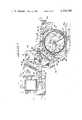
- FIG. 1is a side elevational view of the apparatus of this invention
- FIG. 2is a view looking rearward before the tool bar showing the apparatus set at zero furrow depth
- FIG. 3is essentially a schematic view immediately before the gauge wheel bearings looking rearward showing the furrow walls and mounds formed along the furrow;
- FIG. 4is a sectional view of a gauge wheel and support arm taken along 4--4 of FIG. 1;
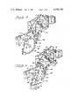
- FIG. 5is a perspective right side view primarily of the right disk and scraper with the associated gauge wheel of the apparatus removed;
- FIG. 6is a view similar to FIG. 5 but with the right disk removed.
- FIG. 7is a partial plan view of the apparatus taken along 7--7 of FIG. 1 showing the equalizer and the gauge wheel adjustment.
- Apparatus 10indicates an equalized furrow forming apparatus for a seed planter.
- Apparatus 10has a frame 11.
- Apparatus 10includes a mounting means 12 for attachment to a mobile power source such as a tractor or tool bar for towing.
- Mounting means 12includes a head bracket 14 having lateral flanges 15 and 16.
- Bracket 14has suitable holes for connection thereof to the tool bar by U-bolts and nuts.
- Dual spaced upper links 19are pivotally connected to the upper part of flanges 15 and 16 at pivots 20 by suitable fasteners and are similarly connected to frame 11 at 21.
- Dual, spaced lower links 22are similarly connected between the noted flanges at pivots 24 and the frame at 25.
- the conventional parallel linkage arrangement describedallows the apparatus to follow the ground contour in operation.
- each means 26extends between channel 28 attached between upper links 19 and support structure which includes tube 29 rigidly connected between links 22 and braces 30 extending between tube 29 (see FIG. 6) and each link 22.
- Means 26includes spring 31 having a hook end 32 which connects with a suitable aperture in brace 30.
- Frame 11is a weldment that provides the necessary structure for all elements of the apparatus. As shown best in FIGS. 1 and 6, frame 11 consists of left 39 and right hand 40 lower sheets that provide the support for the later to be described disks, compaction runner, seed shoe, gauge wheels and equalizer. Frame 11 also includes upper channel 41 which is welded to the sheets and which houses the gauge wheel adjustment and spreader plate 42 which primarily provides support for left and right hand plates 43 and 44 on which are mounted pivots 21 and 25 of the parallel bar linkage. Suitable structure in the plates provide stops as desired for the parallel linkage.
- support 46is welded into sheets 39 and 40 and supports furrow forming disks 47 and 48.
- the axes of the fourteen inch diameter disksare staggered longitudinally by one inch with left disk 47 forward and the axes inclined so that the included angle is 9.5 degrees and the disks substantially contact each other at a point forward of their axes at about 38 degrees downwardly from the horizontal.
- flange type bearings 49are utilized which are rotatably connected to support 46 welded to frame 11 by bolts threaded therein.
- pin 50which loosely supports compaction runner 51.
- Runner 51also has a lower V-shaped configuration that extends slightly below the disks to provide the desired firmed furrow configuration.
- Runner 51is also supported on rearward deflector or shoe 52 via pin 54 with shoe 52 being attached to sheets 39 and 40 by suitable cap screws shown.
- Shoe 52is also spaced for seed tube 55 which extends therebetween to drop seed rearward of the V-shaped portion of the runner 51 into a furrow. Shoe 52 also prevents the movement of loose soil back into the furrow until the seed has been deposited.
- gauge wheel mounting 57Located forwardly of support 46 and connected between sheets 39 and 40 by suitable fasteners is gauge wheel mounting 57.
- Mounting 57has pins 58 and 59 which are staggered longitudinally by one inch as the disks, with pin 58 forward and the pins are threaded into the mounting on axes parallel to the disk axes.
- left hand arm or support 60mounted on pin 58 is left hand arm or support 60.
- Arm 60has a rearwardly extending portion 61 that is connected to gauge wheel assembly 62 and a forwardly extending portion 64.
- Right hand arm of support 65is similar to 60, and has rearward portion 66 for gauge wheel assembly 67 (not shown in FIG. 1) but because of the staggered mounting, has a longer forward upper portion 68 than 64 since they are transversely aligned to contact gauge wheel depth adjustment mechanism 69.
- Gauge wheel assembly 62(see FIG. 4) is typical for both arms 60 and 65 and includes wheel 70 made from composite elements connected by suitable fasteners.
- Each arm 60 (and 65)is connected to a roller bearing 71 with integral shaft by pin 72.
- the bore for bearing 71 in arm 60is inclined laterally outwardly and downwardly by about 2.50° from the associated disk, as shown in FIG. 3, so that radially inward peripheral lip 74 of semi-pneumatic tire 75 will substantially contact its disk at an arc of about 8:30 to 4:30 throughout its travel as shown in broken lines in FIG. 1 and create uncompacted mound 74a of loose soil alongside the furrow wall.
- This arcextends beyond the point of entry of the disk into the soil and its exit and helps prevent the flow of trash between wheel and disk. Primarily it provides a mound of uncompacted soil for deposition into a furrow to provide uniform cover for the seed regardless of soil type in conjunction with the other gauge wheel.
- the flexing of tire 75helps prevent caking of soil thereon.
- Gauge wheel adjustment mechanism 69is shown best in FIGS. 1 and 7. Adjusting mechanism 69 is located in upper channel 41 of frame 11 and is readily accessible from the end of the apparatus remote from the tool bar.
- Mechanism 69includes hollow slide 77 located in channel 41 and supported for movement on pins 78 (one shown) extending through channel 41 and slots in slide 77.
- Slide 77also has a clevis end 79 rigid therewith and extending through a suitable opening through spreader plate 42 and has equalizer assembly 80 extending transversely therethrough. Equalizer assembly 80 extends between the ends of 64 of arm 60 and 68 of arm 65 and forward thereof.
- slide 77will force arms 60 and 65 rearwardly causing the associated wheel assemblies to move toward the soil thereby lifting frame 11 and thus raising the disk to create a shallow furrow. Contrary movement will provide a deeper furrow.
- the movement of slide 77is caused by a depth adjustment rod 81 having a right hand thread at its rearmost end that is engageable with a complementary internal thread in the rearward end of the slide 77.
- Indicator 82is mounted on slide 77 on rod 81. Attached to the end of rod 81 is knob 84. Rotation of knob 84 clockwise will move indicator 82 and slide 77 rearward thus lowering the gauge wheels to create a shallow furrow.
- the indicatorwill also move to the zero gauge position shown in FIG. 2. Turning counterclockwise will produce a counter result. As shown, the indicator indicates an approximate two inch planting depth. Suitable detent means can be provided to maintain knob 84 in the set position.
- Scraperssuch as right hand scraper 86 (see FIG. 5) which extends from frame 11 and is located outside the 8:30 to 4:30 position noted of the contact of the gauge wheel and the disk, will remove soil that sticks to the disk as it leaves the furrow. Normally, this soil falls back alongside the furrow or inside the gauge rim where it moves out as water over a dam. However, when the tool bar is raised, and since each arm 60 and 65 can drop away from equalizer assembly 80 this allows the accumulated scraped soil to drop out from this area aiding in cleaning the apparatus.
- FIG. 1discloses the substantial meeting of the preferably staggered disks and the gauge wheels in the zero position.
- the solid line position of the gauge wheels in FIG. 1discloses a two inch planting furrow, while the upper broken line position shows the approximate highest elevation of the gauge wheels which provides approximately a four inch furrow depth.
- gaugingoccurs (with little change) between the maximum depth of the disks (and laterally adjacent the disks) and where the disks exit the soil.
- the compaction runnerprovides a consistent, V-shaped firmed furrow bottom while the deflector or shoe prevents soil inflow into the furrow and provides support for the seed tube.
- FIG. 3discloses the gauged furrow and the mounds 74a of moist uncompacted soil for later deposition into the furrow after the seed during the planting process.
- equalizer assembly 80includes bar 87 having spherical bearing 88 mounted in spherical opening in the center of bar 87 for movement therein.
- Bar 87has left arm 89 adjacent but forward of arm 64 and arm 90 adjacent and forward of arm 68.
- Pin 91extends between suitable holes in clevis 79 secured to slide 77 and via a fastener rigidly holds spherical bearing 88 therebetween. Therefore, pivotal movement of bar 87 causes rotation thereof about spherical bearing 88. As noted in FIG.
- FIG. 7shows the position taken by equalizer bar 87 when left gauge wheel assembly 62 encounters an obstacle and arm 64 moves 89 of bar 87 forward as shown. Arm 90 is then forced rearwardly to move arm 68 also rearwardly and thus right gauge wheel assembly 67 downwardly.
- gauge wheel 67is on the soil as before, it and wheel assembly 62 will both support the frame with the frame only rising 1/2 of the height of the obstacle.
- wheel 67will drop to the soil and continue to provide a mound of uncompacted soil alongside the furrow.
- the apparatusclearly provides accurately gauged furrow depth wherein gauging is accomplished laterally close to the disks and longitudinally close to the maximum depth achieved by the disks while maintaining desirable furrow characteristics.
- the equalizing featurealso contributes substantially to the accuracy of the furrow depth when obstacles are encountered which are relatively frequent in no-till situations for which applicants have provided the described, staggered disk mounting arrangements.
- the equalizing featurealso contributes substantially to the accuracy of the furrow depth when operating alongside ridges thrown up by tractor tires or when crossing water furrows or tire tracks.
Landscapes
- Life Sciences & Earth Sciences (AREA)
- Soil Sciences (AREA)
- Environmental Sciences (AREA)
- Soil Working Implements (AREA)
Abstract
Description
Claims (2)
Priority Applications (1)
| Application Number | Priority Date | Filing Date | Title |
|---|---|---|---|
| US06/153,975US4356780A (en) | 1980-05-28 | 1980-05-28 | Equalized furrow forming apparatus for a seed planter |
Applications Claiming Priority (1)
| Application Number | Priority Date | Filing Date | Title |
|---|---|---|---|
| US06/153,975US4356780A (en) | 1980-05-28 | 1980-05-28 | Equalized furrow forming apparatus for a seed planter |
Publications (1)
| Publication Number | Publication Date |
|---|---|
| US4356780Atrue US4356780A (en) | 1982-11-02 |
Family
ID=22549504
Family Applications (1)
| Application Number | Title | Priority Date | Filing Date |
|---|---|---|---|
| US06/153,975Expired - LifetimeUS4356780A (en) | 1980-05-28 | 1980-05-28 | Equalized furrow forming apparatus for a seed planter |
Country Status (1)
| Country | Link |
|---|---|
| US (1) | US4356780A (en) |
Cited By (21)
| Publication number | Priority date | Publication date | Assignee | Title |
|---|---|---|---|---|
| US4423788A (en) | 1981-05-20 | 1984-01-03 | International Harvester Co. | Agricultural furrow forming apparatus depth control |
| US4430952A (en)* | 1982-09-07 | 1984-02-14 | Allis-Chalmers Corporation | Planter gauge wheels with adjustable equalizer mechanism |
| US4596200A (en)* | 1982-09-02 | 1986-06-24 | Deutz-Allis Corporation | Row crop planter |
| US4819737A (en)* | 1987-09-24 | 1989-04-11 | J. I. Case Company | Row crop cultivator |
| US5159985A (en)* | 1991-02-06 | 1992-11-03 | Kennametal Inc. | Agricultural insert |
| US5325799A (en)* | 1992-09-25 | 1994-07-05 | Kennametal Inc. | Seed boot insert |
| US5427184A (en)* | 1994-04-07 | 1995-06-27 | Deere & Company | Crank adjusted depth control for an implement |
| US5697308A (en)* | 1995-12-20 | 1997-12-16 | Kennametal Inc. | Seed boot having a wear resistant insert |
| US5785129A (en)* | 1995-12-01 | 1998-07-28 | Keller; Russell J. | Row crop cultivator having a fixed depth of penetration |
| US20060042806A1 (en)* | 2004-08-25 | 2006-03-02 | Friggstad Terrance A | Tillage apparatus having flexible frame and weight distribution system |
| WO2008123829A1 (en)* | 2007-04-05 | 2008-10-16 | Väderstad-Verken Ab | Device for coupling of support wheels at an agricultural machine |
| CN100527936C (en)* | 2003-01-10 | 2009-08-19 | 迪尔公司 | Plough open/close apparatus for agricutural machine |
| US8634992B2 (en) | 2011-01-26 | 2014-01-21 | Precision Planting Llc | Dynamic supplemental downforce control system for planter row units |
| US9144189B2 (en) | 2012-07-25 | 2015-09-29 | Precision Planting Llc | Integrated implement downforce control systems, methods, and apparatus |
| US9179593B2 (en) | 2013-01-09 | 2015-11-10 | Cnh Industrial America Llc | Row unit of an agricultural implement with multiple locations for mounting a gauge wheel |
| US9288937B2 (en) | 2011-08-05 | 2016-03-22 | Precision Planting Llc | Apparatus, systems and methods for row unit downforce control |
| US9763379B2 (en)* | 2015-06-30 | 2017-09-19 | Cnh Industrial America Llc | Replaceable wear insert for a forming point positioned between furrow opening disks |
| CN107295836A (en)* | 2017-07-20 | 2017-10-27 | 西北农林科技大学 | A kind of fertile seeding apparatus of layered deep placement and method |
| CN111295984A (en)* | 2020-02-21 | 2020-06-19 | 山东省农业机械科学研究院 | A ditching and fertilizing transmission device and a ditching and fertilizing device |
| US11510356B2 (en)* | 2019-05-15 | 2022-11-29 | Great Plains Manufacturing, Inc. | Ground opener with floating opener body |
| US20230337574A1 (en)* | 2022-04-22 | 2023-10-26 | Cnh Industrial America Llc | Row unit for a seed-planting implement having a furrow depth adjustment system |
Citations (5)
| Publication number | Priority date | Publication date | Assignee | Title |
|---|---|---|---|---|
| US2191929A (en)* | 1938-05-21 | 1940-02-27 | Deere & Co | Plow |
| US2685243A (en)* | 1950-02-15 | 1954-08-03 | Ford Motor Co | Depth wheel for seed planters |
| FR1261393A (en)* | 1960-04-08 | 1961-05-19 | Device for the hydraulic transmission of a rectilinear movement applicable in particular to agricultural tractors | |
| US4009668A (en)* | 1975-07-07 | 1977-03-01 | Deere & Company | Planter apparatus and method for planting |
| FR2415421A1 (en)* | 1978-01-25 | 1979-08-24 | Nodet Gougis Sa | DEVICE FOR REGULARIZING THE DEPTH OF A Furrow |
- 1980
- 1980-05-28USUS06/153,975patent/US4356780A/ennot_activeExpired - Lifetime
Patent Citations (5)
| Publication number | Priority date | Publication date | Assignee | Title |
|---|---|---|---|---|
| US2191929A (en)* | 1938-05-21 | 1940-02-27 | Deere & Co | Plow |
| US2685243A (en)* | 1950-02-15 | 1954-08-03 | Ford Motor Co | Depth wheel for seed planters |
| FR1261393A (en)* | 1960-04-08 | 1961-05-19 | Device for the hydraulic transmission of a rectilinear movement applicable in particular to agricultural tractors | |
| US4009668A (en)* | 1975-07-07 | 1977-03-01 | Deere & Company | Planter apparatus and method for planting |
| FR2415421A1 (en)* | 1978-01-25 | 1979-08-24 | Nodet Gougis Sa | DEVICE FOR REGULARIZING THE DEPTH OF A Furrow |
Non-Patent Citations (1)
| Title |
|---|
| 5100 Seed Boss Planter White Farm Equipment Brochure, No. 5-258.* |
Cited By (28)
| Publication number | Priority date | Publication date | Assignee | Title |
|---|---|---|---|---|
| US4423788A (en) | 1981-05-20 | 1984-01-03 | International Harvester Co. | Agricultural furrow forming apparatus depth control |
| US4596200A (en)* | 1982-09-02 | 1986-06-24 | Deutz-Allis Corporation | Row crop planter |
| US4430952A (en)* | 1982-09-07 | 1984-02-14 | Allis-Chalmers Corporation | Planter gauge wheels with adjustable equalizer mechanism |
| US4819737A (en)* | 1987-09-24 | 1989-04-11 | J. I. Case Company | Row crop cultivator |
| US5159985A (en)* | 1991-02-06 | 1992-11-03 | Kennametal Inc. | Agricultural insert |
| US5310009A (en)* | 1991-02-06 | 1994-05-10 | Kennametal, Inc. | Agricultural insert |
| US5325799A (en)* | 1992-09-25 | 1994-07-05 | Kennametal Inc. | Seed boot insert |
| US5427184A (en)* | 1994-04-07 | 1995-06-27 | Deere & Company | Crank adjusted depth control for an implement |
| US5785129A (en)* | 1995-12-01 | 1998-07-28 | Keller; Russell J. | Row crop cultivator having a fixed depth of penetration |
| US5697308A (en)* | 1995-12-20 | 1997-12-16 | Kennametal Inc. | Seed boot having a wear resistant insert |
| CN100527936C (en)* | 2003-01-10 | 2009-08-19 | 迪尔公司 | Plough open/close apparatus for agricutural machine |
| US20060042806A1 (en)* | 2004-08-25 | 2006-03-02 | Friggstad Terrance A | Tillage apparatus having flexible frame and weight distribution system |
| US7543657B2 (en) | 2004-08-25 | 2009-06-09 | Cnh Canada, Ltd. | Tillage apparatus having flexible frame and weight distribution system |
| WO2008123829A1 (en)* | 2007-04-05 | 2008-10-16 | Väderstad-Verken Ab | Device for coupling of support wheels at an agricultural machine |
| US8634992B2 (en) | 2011-01-26 | 2014-01-21 | Precision Planting Llc | Dynamic supplemental downforce control system for planter row units |
| US10681854B2 (en) | 2011-01-26 | 2020-06-16 | Precision Planting Llc | Dynamic supplemental downforce control system for planter row units |
| US9288937B2 (en) | 2011-08-05 | 2016-03-22 | Precision Planting Llc | Apparatus, systems and methods for row unit downforce control |
| US9144189B2 (en) | 2012-07-25 | 2015-09-29 | Precision Planting Llc | Integrated implement downforce control systems, methods, and apparatus |
| US9179593B2 (en) | 2013-01-09 | 2015-11-10 | Cnh Industrial America Llc | Row unit of an agricultural implement with multiple locations for mounting a gauge wheel |
| US10750657B2 (en) | 2013-01-09 | 2020-08-25 | Cnh Industrial America Llc | Row unit of an agricultural implement with multiple locations for mounting a gauge wheel |
| US9968028B2 (en) | 2013-01-09 | 2018-05-15 | Cnh Industrial America Llc | Row unit of an agricultural implement with multiple locations for mounting a gauge wheel |
| US9763379B2 (en)* | 2015-06-30 | 2017-09-19 | Cnh Industrial America Llc | Replaceable wear insert for a forming point positioned between furrow opening disks |
| CN107295836A (en)* | 2017-07-20 | 2017-10-27 | 西北农林科技大学 | A kind of fertile seeding apparatus of layered deep placement and method |
| US11510356B2 (en)* | 2019-05-15 | 2022-11-29 | Great Plains Manufacturing, Inc. | Ground opener with floating opener body |
| AU2020276291B2 (en)* | 2019-05-15 | 2025-04-17 | Great Plains Manufacturing, Inc. | Ground opener with floating opener body |
| CN111295984A (en)* | 2020-02-21 | 2020-06-19 | 山东省农业机械科学研究院 | A ditching and fertilizing transmission device and a ditching and fertilizing device |
| US20230337574A1 (en)* | 2022-04-22 | 2023-10-26 | Cnh Industrial America Llc | Row unit for a seed-planting implement having a furrow depth adjustment system |
| US12336451B2 (en)* | 2022-04-22 | 2025-06-24 | Cnh Industrial America Llc | Row unit for a seed-planting implement having a furrow depth adjustment system |
Similar Documents
| Publication | Publication Date | Title |
|---|---|---|
| US4356780A (en) | Equalized furrow forming apparatus for a seed planter | |
| US4493274A (en) | Furrow forming apparatus for a seed planter | |
| US4430952A (en) | Planter gauge wheels with adjustable equalizer mechanism | |
| US4423788A (en) | Agricultural furrow forming apparatus depth control | |
| US4398478A (en) | Seed planter apparatus with covering wheel | |
| US4307674A (en) | Agricultural implement for planting seeds | |
| US4762075A (en) | Seed/fertilizer minimum tillage planter | |
| US4275670A (en) | Seed drill mounting arrangement | |
| US4596200A (en) | Row crop planter | |
| US5235922A (en) | Planter with equalizer between gauge wheels | |
| US4553607A (en) | Ridge cleaning attachment for planters | |
| US4374500A (en) | Seed planter depth control | |
| US11723301B2 (en) | Trailing arm device and assembly with parallel linkage | |
| US3177830A (en) | Seed drill | |
| US5626196A (en) | Seed drill with scraper/soil firming attachment | |
| CA2659013C (en) | Row unit soil finishing apparatus | |
| US4373456A (en) | Agricultural furrow forming apparatus depth control | |
| US12414498B2 (en) | Trench closing assembly | |
| US5645000A (en) | Seed furrow closing apparatus for agricultural planters | |
| US4750441A (en) | Furrow opening assembly | |
| CA1281945C (en) | Opener assembly with depth gauging from a press wheel | |
| US2164543A (en) | Ridge busting device for farm tractors | |
| EP0352865B1 (en) | Device for cutting grooves in the ground | |
| US5685246A (en) | Planting assembly for seed drill | |
| US3202119A (en) | Covering devices for grain drills |
Legal Events
| Date | Code | Title | Description |
|---|---|---|---|
| AS | Assignment | Owner name:FIDELITY UNION BANK, TRUSTEE Free format text:SECURITY INTEREST;ASSIGNOR:INTERNATIONAL HARVESTER COMPANY;REEL/FRAME:003970/0963 Effective date:19811101 Owner name:PATTERSON, LINDA L., TRUSTEE Free format text:SECURITY INTEREST;ASSIGNOR:INTERNATIONAL HARVESTER COMPANY;REEL/FRAME:003970/0963 Effective date:19811101 Owner name:FIDELITY UNION BANK, TRUSTEE, ILLINOIS Free format text:SECURITY INTEREST;ASSIGNOR:INTERNATIONAL HARVESTER COMPANY;REEL/FRAME:003970/0963 Effective date:19811101 Owner name:PATTERSON, LINDA L., TRUSTEE, ILLINOIS Free format text:SECURITY INTEREST;ASSIGNOR:INTERNATIONAL HARVESTER COMPANY;REEL/FRAME:003970/0963 Effective date:19811101 | |
| STCF | Information on status: patent grant | Free format text:PATENTED CASE | |
| AS | Assignment | Owner name:INTERNATIONAL HARVESTER COMPANY, ILLINOIS Free format text:ASSIGNMENT OF ASSIGNORS INTEREST;ASSIGNOR:FIRST FIDELTY BANK, NATIONAL ASSOCIATION PATTERSON, LINDA L.; TRUSTEES;REEL/FRAME:004357/0949 Effective date:19850131 Owner name:INTERNATIONAL HARVESTER COMPANY, 401 NORTH MICHIGA Free format text:ASSIGNMENT OF ASSIGNORS INTEREST.;ASSIGNOR:FIRST FIDELTY BANK, NATIONAL ASSOCIATION PATTERSON, LINDA L.; TRUSTEES;REEL/FRAME:004357/0949 Effective date:19850131 | |
| AS | Assignment | Owner name:J.I. CASE COMPANY A DE CORP Free format text:ASSIGNMENT OF ASSIGNORS INTEREST;ASSIGNOR:INTERNATIONAL HARVESTER COMPANY A DE CORP;REEL/FRAME:004379/0536 Effective date:19850131 Owner name:J.I. CASE COMPANY A DE CORP Free format text:ASSIGNMENT OF ASSIGNORS INTEREST.;ASSIGNOR:INTERNATIONAL HARVESTER COMPANY A DE CORP;REEL/FRAME:004379/0536 Effective date:19850131 | |
| AS | Assignment | Owner name:CASE CORPORATION, A CORP. OF DELAWARE Free format text:CHANGE OF NAME;ASSIGNOR:J. I. CASE COMPANY, A CORP. OF DELAWARE;REEL/FRAME:005741/0138 Effective date:19891229 | |
| AS | Assignment | Owner name:CASE EQUIPMENT CORPORATION, WISCONSIN Free format text:ASSIGNMENT OF ASSIGNORS INTEREST;ASSIGNOR:CASE CORPORATION;REEL/FRAME:007125/0717 Effective date:19940623 | |
| AS | Assignment | Owner name:CASE CORPORATION, WISCONSIN Free format text:CHANGE OF NAME;ASSIGNOR:CASE EQUIPMENT CORPORATION;REEL/FRAME:007132/0468 Effective date:19940701 |