US4356703A - Refrigeration defrost control - Google Patents
Refrigeration defrost controlDownload PDFInfo
- Publication number
- US4356703A US4356703AUS06/174,243US17424380AUS4356703AUS 4356703 AUS4356703 AUS 4356703AUS 17424380 AUS17424380 AUS 17424380AUS 4356703 AUS4356703 AUS 4356703A
- Authority
- US
- United States
- Prior art keywords
- defrost
- evaporator
- refrigerant
- valve means
- liquid line
- Prior art date
- Legal status (The legal status is an assumption and is not a legal conclusion. Google has not performed a legal analysis and makes no representation as to the accuracy of the status listed.)
- Expired - Lifetime
Links
Images


Classifications
- F—MECHANICAL ENGINEERING; LIGHTING; HEATING; WEAPONS; BLASTING
- F25—REFRIGERATION OR COOLING; COMBINED HEATING AND REFRIGERATION SYSTEMS; HEAT PUMP SYSTEMS; MANUFACTURE OR STORAGE OF ICE; LIQUEFACTION SOLIDIFICATION OF GASES
- F25B—REFRIGERATION MACHINES, PLANTS OR SYSTEMS; COMBINED HEATING AND REFRIGERATION SYSTEMS; HEAT PUMP SYSTEMS
- F25B5/00—Compression machines, plants or systems, with several evaporator circuits, e.g. for varying refrigerating capacity
- F25B5/02—Compression machines, plants or systems, with several evaporator circuits, e.g. for varying refrigerating capacity arranged in parallel
- F—MECHANICAL ENGINEERING; LIGHTING; HEATING; WEAPONS; BLASTING
- F25—REFRIGERATION OR COOLING; COMBINED HEATING AND REFRIGERATION SYSTEMS; HEAT PUMP SYSTEMS; MANUFACTURE OR STORAGE OF ICE; LIQUEFACTION SOLIDIFICATION OF GASES
- F25B—REFRIGERATION MACHINES, PLANTS OR SYSTEMS; COMBINED HEATING AND REFRIGERATION SYSTEMS; HEAT PUMP SYSTEMS
- F25B47/00—Arrangements for preventing or removing deposits or corrosion, not provided for in another subclass
- F25B47/02—Defrosting cycles
- F25B47/022—Defrosting cycles hot gas defrosting
- F—MECHANICAL ENGINEERING; LIGHTING; HEATING; WEAPONS; BLASTING
- F25—REFRIGERATION OR COOLING; COMBINED HEATING AND REFRIGERATION SYSTEMS; HEAT PUMP SYSTEMS; MANUFACTURE OR STORAGE OF ICE; LIQUEFACTION SOLIDIFICATION OF GASES
- F25D—REFRIGERATORS; COLD ROOMS; ICE-BOXES; COOLING OR FREEZING APPARATUS NOT OTHERWISE PROVIDED FOR
- F25D21/00—Defrosting; Preventing frosting; Removing condensed or defrost water
- F25D21/002—Defroster control
- F25D21/008—Defroster control by timer
Definitions
- the present inventionpertains to refrigeration systems employing hot gas defrosting, and control systems therefor. Specifically, the invention relates to improvements in the type of refrigeration defrost system wherein at least one evaporator is defrosted by hot gas while one or more evaporators remain in refrigeration operation.
- One well established method of defrosting evaporators in refrigeration systemsis by forcing hot gas from the compressor of the system through the evaporator so that the evaporator acts as a condenser.
- the heat given up by the evaporator under those conditionsmelts the ice and frost that has formed on the evaporator coils and fins during normal refrigeration operation.
- the hot gas defrostingis accomplished by diverting valves in the refrigerant path which are switched to accomplish defrosting mode to divert the hot gas through the evaporator, either in the same direction as the refrigerant flow during refrigeration, or in the opposite direction.
- the defrostingcan be accomplished on a time basis so that a defrost cycle is run at selected intervals, or it can be done on a demand basis through the use of frost sensors and the like for detecting frost buildup on the evaporator coils.
- the present inventionprovides improved control over several areas of the hot gas defrosting process so as to provide efficient defrosting at a high speed and with little or no waste of energy on the defrosting process.
- the inventionis used in conjunction with restricting the refrigeration system during a defrost cycle by switching the condenser and perhaps other components out of the refrigerant path. By thus restricting the system, all heat absorbed by the refrigerating evaporator or evaporators is used in the defrosting process. This helps to provide maximum speed of defrosting and maximum energy efficiency, so there is little or no waste heat.
- the control system of the present inventionoperates to provide the correct amount of refrigerant charge in the operating part of the system during the defrost cycle.
- control systemeffectively determines where the liquid refrigerant will be within the system and controls the transition from defrost mode back to refrigeration mode in order to prevent the liquid refrigerant from entering the suction line.
- Improvements in the design of the evaporators in terms of refrigerant path circuiting and valving controlcan advantageously be used with the above improvements in defrost cycle control, to achieve improved speed and uniformity in the defrosting of the evaporators.
- an improved defrost control systemfor a refrigeration system of the type which includes a compressor, a condenser, at least two evaporators, and interconnecting conduits to form refrigerant flow paths through the system.
- a liquid line valveis provided in the refrigerant path between the condenser and the evaporators, and diverting valve means are provided for selectively establishing, in conjunction with the liquid valve means, a defrost loop through at least one evaporator whereby hot gas is introduced through the defrosting evaporator, where it is condensed to form liquid refrigerant which then continues through at least one evaporator which remains in refrigeration mode.
- Control meansare provided for controlling the operation of the liquid line valve and the diverting valve means, so that to begin a defrost cycle the liquid line valve is closed to allow the system to pump down to a predetermined amount of refrigerant charge in the defrost loop, at which point the diverting valve means are operated to establish refrigerant flow through the defrost loop.
- a defrost receiveris provided between the liquid line valve and the evaporators, to serve as a temporary storage reservoir for the liquid condensed by the defrosting evaporator, and to serve as a source for the refrigerating evaporator or evaporators.
- control meansis adapted to temporarily open the liquid line valve prior to a defrost cycle, as it may otherwise be operating under thermostatic control, to assure that there will be more than an adequate supply of refrigerant in the defrost loop.
- the valveis then closed for pump down to bring the defrost loop down to the correct amount of refrigerant charge for defrost.
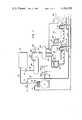
- FIG. 1is a schematic diagram of a refrigerant system with improved hot gas defrost control according to the present invention
- FIG. 2is an electrical diagram of the control system for the defrost control of the system of FIG. 1;
- FIG. 3is a diagram illustrating a preferred refrigerant circuiting and valving path in an evaporator for improved efficieny of defrosting.
- reference number 10designates the compressor of the refrigeration system. It is connected to receive a suction line 11 which is connected to its intake, and a discharge line 12 which is connected to the outlet of the compressor.
- the compressoris driven by an electrical motor and incorporates a control for starting and stopping the compressor based upon pressure in the suction line, as is conventional in refrigeration systems.
- the compressorcan be a single unit, or a plurality of units as required by capacity considerations for the system, and a sequencing control can be used as is generally known in the art for matching compressor capacity to system requirements in the case of multiple compressors.
- Discharge line 12connects to a three-way diverting valve 13, which is controlled by electrical control 14. Hot gas refrigerant in discharge line 12 passes through valve 13 either to line 15 or line 16, depending upon the position of the valve.
- Line 15connects to condenser 17, which may be any type of known condenser or a plurality of interconnected condensers which may be mounted on roof top remote from the rest of the system.
- the outlet of condenser 17connects through line 18 to receiver 20.
- the improved head pressure control of U.S. Pat. No. 4,136,528, assigned to the same assignee as the present inventioncan be used in conjunction with the refrigeration system, in which case a control valve 21 and controls therefor as set forth in the above-mentioned patent can be incorporated. In that case control valve 21 would connect between the outlet of condenser 17, line 18, and a bypass branch of line 15 for control of system head pressure by control of condenser flooding.
- Line 22conveys liquid refrigerant from receiver 20 to liquid line shutoff valve 25, which is operated by solenoid 26. Valve 25 is connected to check valve 27 which in turn connects to defrost receiver 30.
- Liquid lines for the evaporatorsconnect from defrost receiver 30.
- these liquid linesare number 31, 32, and 33, it being understood that the number of such lines would correspond to the number of evaporators in a given system.
- two evaporator loads 40, 41are shown, and a third evaporator 42 is shown in broken lines to indicate that additional evaporator loads can be connected depending upon system size, as the invention is not limited to any paticular number of evaporators.
- Liquid line 31connects to thermostatic expansion valve (TEV) 34, and the output of valve 34 connects to evaporator 40.
- a branch 35connects back through check valve 36 to liquid line 31, for use during defrost mode.
- the outlet of evaporator 40is connected to line 37, and sensing bulb 38 for TEV 34 is placed in contact with the refrigerant at the evaporator outlet as is conventional.
- Liquid line 37connects to a three-way diverting valve 50 which is operated by electrical control 51.
- One part of diverting valve 50connects to line 16, and the other part connects to the suction line 11.
- Evaporator 41is similarly connected from liquid line 32 by means of TEV 44, branch 45, and check valve 46.
- the outlet of evaporator 41connects via line 47 to three-way diverting valve 60, the other parts of which connect to line 16 and suction line 11.
- Valve 60is operated by electrical control 61.
- Sensing bulb 48 for TEV 44is in contact with line 47.
- similar components and connectionswould be made to receiver 30 and to lines 11 and 16.
- a pressure limit switch 65is included in line 16, and it consists of a pressure responsive element connected to control a pair of switch contacts 65a and 65b.
- the system of FIG. 1thus described provides a refrigerant flow path during normal refrigeration from compressor 10, through condenser 17 (or bypassing condenser 17 under control valve 21, is applicable), through receivers 20 and 30 to the evaporators. Vapor from the evaporators is returned through suction line 11 to the compressor 10. In defrosting mode, deverting valve 13 and liquid line shutoff valve 25 are operated to restrict the system and to temporarily cut condenser 17 and receiver 20 out of the refrigerant path. Check valve 27 restricts backflow into the receiver, since typically solenoid valves restrict flow in only one direction. Hot gas then proceeds through line 16 to flow in reverse direction through the evaporator or evaporators being defrosted.
- diverting valve 50would be actuated to conduct hot gas from line 16 through evaporator 40, where it is condensed, thereby giving up heat to defrost the evaporator.
- Liquid refrigerantpasses into defrost receiver 30, from where it is fed to one or more evaporators that remain in refrigeration mode. It is important that at least one evaporator remain in normal refrigerating mode, so that the defrosting evaporator or evaporators acts as a condenser for the refrigerant to be utilized in the evaporator or evaporators that remain in refrigeration mode, as refrigerant is cycled through the restricted operating part of the system. In the case of a two evaporator system, one would be in defrost while the other remains in refrigeration mode. In the case of larger systems, multiple evaporators could be in defrost and refrigeration mode.
- FIG. 1 in the preferred embodimentis described in terms of hot gas flow path through the defrosting evaporator in a direction opposite to the path of flow of refrigerant during refrigeration mode, it will be understood that the direction of flow during defrost is not critical, and by suitable valving modifications, could be through the evaporators in the same direction as refrigeration mode flow. Also, while branches 35, 45, and corresponding check valves 36, 46 are used as the refrigerant flow path around the TEV's 34, 44 during defrost mode, they are not essential, and probably could be omitted.
- a source of electrical poweris applied to terminals 70, 71.
- defrostis controlled on a time basis whereby defrosting of the individual evaporators is initiated on a programmed time sechedule.
- initiation of defrost cyclescould be established on a demand basis as is generally known in the art, through use of frost sensors on the evaporators.
- timer motor 73is connected to the power supply and operates through mechanical linkages, suggested by broken lines 74, 75 to operate sets of switches. Specifically, single pole double throw switch 76 and single pole single throw switch 77 are operated by the motor through linkage 74, and single pole double throw switch 78 and single pole single throw switch 79 are operated by linkage 75.
- switches 76 and 78are connected to power line 71.
- the normally closed terminal of switch 76connects to contactor 80 which controls the energization for the fan motors (not shown) for evaporator 40.
- the other side of contactor 80connects through a thermostat 82, the pole of which connects to power lead 70.
- Thermostat 82is connected to evaporator 40, and is used to sense completion of defrosting of evaporator 40, and to terminate the defrost cycle.
- switch 78connects to contactor 81 and thermostat 83 for evaporator 41.
- switches 76 and 78connect to lead 84, a branch of which connects to the relay driver R3, the other side of which connects to power lead 70.
- Another branch of lead 84connects to reset solenoid 85 which is mechanically coupled to reset switches 76 and 77.
- a further branch of lead 84connects to reset solenoid 86 which is mechanically coupled to reset switches 78 and 79.
- solenoid 85connects to lead 90, a branch of which connects to another contact 82b of thermostat 82, and a branch of which connects to pressure limit switch 65a.
- reset solenoid 86connects to lead 91, a branch of which connects to contact 83b of thermostat 83, and another branch of which connects to a pressure limit switch 65b.
- the normally open contacts for this relayare labeled R1, the corresponding designations are used for the other relays in the circuit.
- Time delay relays 100, 101, and 102are used in FIG. 2. These are self-contained devices, electronically operated, which function to close their switching contacts following a predetermined time delay from the time that power is first applied across the device. Such units are generally known and available in the prior art. Alternatively, thermal type time delay relays could be used.
- Time delay device 100connects between leads 92 annd 93, and delay device 101 connects between leads 93 and 94.
- a branch of lead 93connects to relay driver R2, the other side of which connects to power lead 70.
- a branch of lead 94connects to valve actuator 14 for three-way diverting valve 13.
- Other branches of lead 94connect to switches 77 and 79.
- Valve actuators 51 and 61connect respectively from switches 77 and 79 to power lead 70, for controlling three-way diverting valves 50 and 60, respectively.
- Delay device 102connects from lead 71 to normally closed contacts R2.
- the other side of contacts R2connects to lead 95, one branch of which connects to contacts R1, and the other branch of which connects to thermostat 96, which is the room or cold box thermostat for the refrigerated space.
- thermostat 96 and contacts R1connect via lead 97 to solenoid 26 which operates liquid line shutoff valve 25 of FIG. 1. If a manual on-off switch for the entire system is desired, it can be placed in lead 71 at the point indicated by reference number 98, which will function to de-energize solenoid 26 and shut off the liquid line.
- valve actuators 51, 61 and 14are de-energized, and solenoid 26 is energized to hold open the liquid line.
- solenoid valveWhen the solenoid valve is de-energized, valve 25 shuts off the liquid line.
- a defrost cycleis initiated by timer motor 73 reaching a position to actuate the switches for one of the evaporators, although as pointed out above, suitable deman controls could be used instead.
- the time schedule for the frequency of defrost intervalsmay be programmed to a suitable selection of timer motor 73, as is generally known in the art, in consideration of the anticipated or observed frost buildup rates on the evaporators in a given installation. Assume for purposes of illustration that the time for defrost of evaporator 40 occurs. Switches 76 and 77 are actuated. This de-energizes contactor 80 for the fans for evaporator 40, since it is desired that the evaporator fans be off during defrost mode.
- liquid line shutoff valve 25might be open or closed, since it is operating under control of thermostat 96.
- the first step upon initiation of the defrost cycleis to make sure the liquid line solenoid is open for a period of time, usually several minutes, so that there will be more than adequate refrigerant in the defrost loop at the time the actual defrosting mode takes place. This is accomplished by closing contacts R1, which occurs when contacts R3 are closed. This closes the circuit from power lead 70, through solenoid driver 26, contacts R1, normally closed contacts R2 to delay device 102, which after its delay period, will complete the circuit to power lead 71.
- delay device 102is not needed at this point, and could be bypassed by additional relay logic if desired.
- the delay provided by device 102is used upon re-energizing of solenoid 26 at the end of defrost, as it will be explained in more detail below, and for simplicity and convenience it is allowed to provide its delay at any time solenoid 26 is to be energized.
- the time delay of device 102must be much shorter than the delay of device 100 for proper operation. In a preferred embodiment using two evaporators, delay device 100 was chosen for three minutes, and delay device 102 was chosen for one minute. This is to allow sufficient time for refrigeration to continue with liquid line shutoff valve 25 open so that there will be more than adequate refrigerant in the defrost loop.
- the next stepis to close liquid line shutoff valve 25 and initiate a controlled partial pump down of the system downstream of that valve prior to fully switching to defrost mode. This is accomplished by delaying the switching of the diverting valves until the system that will be included in the defrost loop is pumped down to the optimum amount of refrigerant charge. In the preferred embodiment this is accomplished by a time delay for the switching of diverting valves 13 and 50 or 60 for a time interval following the closing of liquid line shutoff valve 25. This is accomplished by the opening of relay contacts R2 at the end of the three minute delay of device 100 which shuts off the liquid line, and initiates the time delay of device 101 which, in the two evaporator embodiment mentioned above, is 45 seconds.
- this pump down periodwould be calculated or empirically determined based upon the coil size and refrigerating rate for the coils.
- Thisempties the defrost receiver 30 down to the optimum amount of charge for the defrost loop.
- the condenser and receiver 20At the end of the delay provided by device 101, its contacts are closed, completing the circuit through to diverting valve actuators 14 and 51.
- Thiscauses the condenser and receiver 20 to be cut off, and the discharge of compressor 10 to proceed through line 16, valve 50 and line 37 to evaporator 40.
- the hot gasmelts the frost buildup on the evaporator coils while it is being condensed to liquid form.
- the liquid refrigerantproceeds through line 31 to defrost receiver 30, where it serves as a source of liquid refrigerant for evaporator 41, which continues to operate in refrigeration mode.
- thermostat 82switches when the evaporator begins to heat up after the ice has melted. When this occurs, contact 82b will be connected to power line 70, and reset solenoid 85 will be energized to reset switches 76 and 77. Alternatively, in the event of abnormally high pressure in line 16, pressure limit switch 65 would close contact 65a which would also energize reset solenoid 85.
- liquid line shutoff valve 25Since liquid line shutoff valve 25 remains closed, there is a limited supply of liquid refrigerant to feed into evaporator 40, i.e., namely the refrigerant which partially fills defrost receiver 30. This is intentionally done to avoid flood back of liquid refrigerant which would otherwise occur into suction line 11. If valve 25 was opened at the same time that diverter valve 50 returned to refrigeration position, a large supply of liquid refrigerant would be available for feeding evaporator 40. Due to the thermal inertia of sensing bulb 38 and TEV 34, there is a danger that an appreciable amount of liquid could pass completely through evaporator 40 and into the suction line before the TEV would be able to react and close off the flow.
- reference number 110generally designates an evaporator
- reference numbers 111, 112, and 113designate in schematic form individual refrigerant paths or circuits through the evaporator. It will be understood that in practice any number of such paths may be present, but only three are shown for purposes of illustration.
- Path 113represents the lowest positioned circuit or group of circuits in the evaporator.
- a liquid line such as liquid line 31bring refrigerant to TEV 34, which connects via capilary tube 34a to sensing bulb 38 in contact with the suction line 37.
- TEV 34connects to a distributor manifold 115 which has a number of distributing tubes 121, 122, 123, corresponding to the individual circuits in the evaporator.
- the individual circuitsconnect to a manifold 125, which in turn connects to suction line 37.
- branch 35 and check valve 36are provided so that condensed refrigerant can move from manifold 115 to liquid line 31 during defrost mode.
- defrostingtakes place fastest in the upper regions of the evaporator, and towards the side of the evaporator that receives the hot gas. In FIG. 3, this would means that defrosting would occur more rapidly towards the top and towards the right side of the evaporator.
- the lowermost and liquid sidewere very difficult to defrost, greatly lengthening the necessary time for the defrost cycle.
- One factoris the static head difference between the upper and lower circuits due to the vertical height of the unit.
- Another factoris the heat convection of the air in close contact with the coils of the evaporator. As the evaporator heats up during defrost, the heated air moves towards the top of the evaporator, increasing the melt rate at the top, but not at the bottom of the evaporator.
- Another factoris heat convection within the refrigerant tubes themselves, as in manifold 125, which may send the hottest gas to the top circuits rather than to the lower circuits.
- an additional refrigerant pathincluding check valve 120 and conduits 121 and 122 is provided as a return path for refrigerant from the lowest circuit 113.
- This pathis shorter and of larger diameter than distribution tube 123.
- This pathconnects from the distribution tube 123 at a point near the connection to the evaporator, to liquid line 31 below the TEV.
- the check valveis necessary to prevent flow in the wrong direction during normal refrigeration.
- This additional pathprovides a liquid flow path with less resistance because of larger diameter, shorter distance, and a lower elevation and therefore with less static head disadvantage.
- An important benefit provided by the present inventionis energy efficiency during defrost.
- the defrostis essentially "free" in that all of the compressor energy is going into providing refrigeration at the same time that defrosting is taking place.
- refrigeration stops during the defrost cyclebut the energy draw from the compressor continues at a higher rate, with the result that defrosting often requires 10 to 15 percent of the total system energy.
- Another advantage of the present inventionis fast defrost, in the range of 6 to 12 minutes as compared to perhaps double that time for electric defrost.
- a further advantage of the present inventionis providing a relatively constant freezer temperature. Since the majority of cooling continues during defrost, there is negligible warmup of the refrigerated box or space during defrost. This is beneficial to the product being maintained in the cooled space, and it also minimizes the amount of frost buildup on the walls, ceiling, etc. of the freezer walls due to changing dew points normally associated with box warmup during defrost.
Landscapes
- Engineering & Computer Science (AREA)
- Physics & Mathematics (AREA)
- Mechanical Engineering (AREA)
- Thermal Sciences (AREA)
- General Engineering & Computer Science (AREA)
- Chemical & Material Sciences (AREA)
- Combustion & Propulsion (AREA)
- Defrosting Systems (AREA)
Abstract
Description
Claims (8)
Priority Applications (1)
| Application Number | Priority Date | Filing Date | Title |
|---|---|---|---|
| US06/174,243US4356703A (en) | 1980-07-31 | 1980-07-31 | Refrigeration defrost control |
Applications Claiming Priority (1)
| Application Number | Priority Date | Filing Date | Title |
|---|---|---|---|
| US06/174,243US4356703A (en) | 1980-07-31 | 1980-07-31 | Refrigeration defrost control |
Publications (1)
| Publication Number | Publication Date |
|---|---|
| US4356703Atrue US4356703A (en) | 1982-11-02 |
Family
ID=22635417
Family Applications (1)
| Application Number | Title | Priority Date | Filing Date |
|---|---|---|---|
| US06/174,243Expired - LifetimeUS4356703A (en) | 1980-07-31 | 1980-07-31 | Refrigeration defrost control |
Country Status (1)
| Country | Link |
|---|---|
| US (1) | US4356703A (en) |
Cited By (29)
| Publication number | Priority date | Publication date | Assignee | Title |
|---|---|---|---|---|
| EP0123554A3 (en)* | 1983-04-23 | 1985-05-22 | Daikin Industries, Limited | Refrigeration unit |
| US4736594A (en)* | 1986-08-06 | 1988-04-12 | Pao Peter Y M | Method and apparatus for controlling refrigeration systems |
| GB2262364A (en)* | 1991-12-12 | 1993-06-16 | So Fine | Refrigerated units for the display of goods |
| US5415005A (en)* | 1993-12-09 | 1995-05-16 | Long Island Lighting Company | Defrost control device and method |
| US5575158A (en)* | 1994-10-05 | 1996-11-19 | Russell A Division Of Ardco, Inc. | Refrigeration defrost cycles |
| US20040103681A1 (en)* | 2000-09-01 | 2004-06-03 | Kare Aflekt | Method and arrangement for defrosting a vapor compression system |
| US20070068188A1 (en)* | 2005-09-29 | 2007-03-29 | Tecumseh Products Company | Ice maker circuit |
| US20090071175A1 (en)* | 2007-09-19 | 2009-03-19 | Emerson Climate Technologies, Inc. | Refrigeration monitoring system and method |
| US7878006B2 (en) | 2004-04-27 | 2011-02-01 | Emerson Climate Technologies, Inc. | Compressor diagnostic and protection system and method |
| US8160827B2 (en) | 2007-11-02 | 2012-04-17 | Emerson Climate Technologies, Inc. | Compressor sensor module |
| US8475136B2 (en) | 2003-12-30 | 2013-07-02 | Emerson Climate Technologies, Inc. | Compressor protection and diagnostic system |
| US8590325B2 (en) | 2006-07-19 | 2013-11-26 | Emerson Climate Technologies, Inc. | Protection and diagnostic module for a refrigeration system |
| US20140245764A1 (en)* | 2011-09-30 | 2014-09-04 | Daikin Industries, Ltd. | Refrigerant cycle system |
| US8964338B2 (en) | 2012-01-11 | 2015-02-24 | Emerson Climate Technologies, Inc. | System and method for compressor motor protection |
| US8974573B2 (en) | 2004-08-11 | 2015-03-10 | Emerson Climate Technologies, Inc. | Method and apparatus for monitoring a refrigeration-cycle system |
| US9140728B2 (en) | 2007-11-02 | 2015-09-22 | Emerson Climate Technologies, Inc. | Compressor sensor module |
| US9285802B2 (en) | 2011-02-28 | 2016-03-15 | Emerson Electric Co. | Residential solutions HVAC monitoring and diagnosis |
| US9310439B2 (en) | 2012-09-25 | 2016-04-12 | Emerson Climate Technologies, Inc. | Compressor having a control and diagnostic module |
| US9310094B2 (en) | 2007-07-30 | 2016-04-12 | Emerson Climate Technologies, Inc. | Portable method and apparatus for monitoring refrigerant-cycle systems |
| US9480177B2 (en) | 2012-07-27 | 2016-10-25 | Emerson Climate Technologies, Inc. | Compressor protection module |
| US9551504B2 (en) | 2013-03-15 | 2017-01-24 | Emerson Electric Co. | HVAC system remote monitoring and diagnosis |
| US9638436B2 (en) | 2013-03-15 | 2017-05-02 | Emerson Electric Co. | HVAC system remote monitoring and diagnosis |
| US9765979B2 (en) | 2013-04-05 | 2017-09-19 | Emerson Climate Technologies, Inc. | Heat-pump system with refrigerant charge diagnostics |
| US9772124B2 (en) | 2013-03-13 | 2017-09-26 | Nortek Air Solutions Canada, Inc. | Heat pump defrosting system and method |
| US9791175B2 (en) | 2012-03-09 | 2017-10-17 | Carrier Corporation | Intelligent compressor flooded start management |
| US9823632B2 (en) | 2006-09-07 | 2017-11-21 | Emerson Climate Technologies, Inc. | Compressor data module |
| US10274210B2 (en) | 2010-08-27 | 2019-04-30 | Nortek Air Solutions Canada, Inc. | Heat pump humidifier and dehumidifier system and method |
| US10488090B2 (en) | 2013-03-15 | 2019-11-26 | Emerson Climate Technologies, Inc. | System for refrigerant charge verification |
| US11619431B2 (en) | 2018-04-13 | 2023-04-04 | Carrier Corporation | Method of defrosting a multiple heat absorption heat exchanger refrigeration system |
Citations (5)
| Publication number | Priority date | Publication date | Assignee | Title |
|---|---|---|---|---|
| US2139297A (en)* | 1937-03-06 | 1938-12-06 | York Ice Machinery Corp | Refrigeration |
| US3273635A (en)* | 1964-04-17 | 1966-09-20 | Hupp Corp. | Heat pump controls |
| US3453838A (en)* | 1967-03-10 | 1969-07-08 | Dunham Bush Inc | Refrigeration system |
| US4122688A (en)* | 1976-07-30 | 1978-10-31 | Hitachi, Ltd. | Refrigerating system |
| US4122686A (en)* | 1977-06-03 | 1978-10-31 | Gulf & Western Manufacturing Company | Method and apparatus for defrosting a refrigeration system |
- 1980
- 1980-07-31USUS06/174,243patent/US4356703A/ennot_activeExpired - Lifetime
Patent Citations (5)
| Publication number | Priority date | Publication date | Assignee | Title |
|---|---|---|---|---|
| US2139297A (en)* | 1937-03-06 | 1938-12-06 | York Ice Machinery Corp | Refrigeration |
| US3273635A (en)* | 1964-04-17 | 1966-09-20 | Hupp Corp. | Heat pump controls |
| US3453838A (en)* | 1967-03-10 | 1969-07-08 | Dunham Bush Inc | Refrigeration system |
| US4122688A (en)* | 1976-07-30 | 1978-10-31 | Hitachi, Ltd. | Refrigerating system |
| US4122686A (en)* | 1977-06-03 | 1978-10-31 | Gulf & Western Manufacturing Company | Method and apparatus for defrosting a refrigeration system |
Cited By (68)
| Publication number | Priority date | Publication date | Assignee | Title |
|---|---|---|---|---|
| US4602485A (en)* | 1983-04-23 | 1986-07-29 | Daikin Industries, Ltd. | Refrigeration unit including a hot gas defrosting system |
| US4688392A (en)* | 1983-04-23 | 1987-08-25 | Daikin Industries, Ltd. | Refrigeration unit including a hot gas defrosting system |
| EP0123554A3 (en)* | 1983-04-23 | 1985-05-22 | Daikin Industries, Limited | Refrigeration unit |
| US4736594A (en)* | 1986-08-06 | 1988-04-12 | Pao Peter Y M | Method and apparatus for controlling refrigeration systems |
| GB2262364A (en)* | 1991-12-12 | 1993-06-16 | So Fine | Refrigerated units for the display of goods |
| US5415005A (en)* | 1993-12-09 | 1995-05-16 | Long Island Lighting Company | Defrost control device and method |
| US5575158A (en)* | 1994-10-05 | 1996-11-19 | Russell A Division Of Ardco, Inc. | Refrigeration defrost cycles |
| US20040103681A1 (en)* | 2000-09-01 | 2004-06-03 | Kare Aflekt | Method and arrangement for defrosting a vapor compression system |
| US6931880B2 (en)* | 2000-09-01 | 2005-08-23 | Sinvent As | Method and arrangement for defrosting a vapor compression system |
| US8475136B2 (en) | 2003-12-30 | 2013-07-02 | Emerson Climate Technologies, Inc. | Compressor protection and diagnostic system |
| US10335906B2 (en) | 2004-04-27 | 2019-07-02 | Emerson Climate Technologies, Inc. | Compressor diagnostic and protection system and method |
| US8474278B2 (en) | 2004-04-27 | 2013-07-02 | Emerson Climate Technologies, Inc. | Compressor diagnostic and protection system and method |
| US7905098B2 (en) | 2004-04-27 | 2011-03-15 | Emerson Climate Technologies, Inc. | Compressor diagnostic and protection system and method |
| US20110144944A1 (en)* | 2004-04-27 | 2011-06-16 | Emerson Climate Technologies, Inc. | Compressor diagnostic and protection system and method |
| US9121407B2 (en) | 2004-04-27 | 2015-09-01 | Emerson Climate Technologies, Inc. | Compressor diagnostic and protection system and method |
| US7878006B2 (en) | 2004-04-27 | 2011-02-01 | Emerson Climate Technologies, Inc. | Compressor diagnostic and protection system and method |
| US9669498B2 (en) | 2004-04-27 | 2017-06-06 | Emerson Climate Technologies, Inc. | Compressor diagnostic and protection system and method |
| US9046900B2 (en) | 2004-08-11 | 2015-06-02 | Emerson Climate Technologies, Inc. | Method and apparatus for monitoring refrigeration-cycle systems |
| US9081394B2 (en) | 2004-08-11 | 2015-07-14 | Emerson Climate Technologies, Inc. | Method and apparatus for monitoring a refrigeration-cycle system |
| US9304521B2 (en) | 2004-08-11 | 2016-04-05 | Emerson Climate Technologies, Inc. | Air filter monitoring system |
| US9690307B2 (en) | 2004-08-11 | 2017-06-27 | Emerson Climate Technologies, Inc. | Method and apparatus for monitoring refrigeration-cycle systems |
| US9086704B2 (en) | 2004-08-11 | 2015-07-21 | Emerson Climate Technologies, Inc. | Method and apparatus for monitoring a refrigeration-cycle system |
| US8974573B2 (en) | 2004-08-11 | 2015-03-10 | Emerson Climate Technologies, Inc. | Method and apparatus for monitoring a refrigeration-cycle system |
| US9017461B2 (en) | 2004-08-11 | 2015-04-28 | Emerson Climate Technologies, Inc. | Method and apparatus for monitoring a refrigeration-cycle system |
| US9021819B2 (en) | 2004-08-11 | 2015-05-05 | Emerson Climate Technologies, Inc. | Method and apparatus for monitoring a refrigeration-cycle system |
| US9023136B2 (en) | 2004-08-11 | 2015-05-05 | Emerson Climate Technologies, Inc. | Method and apparatus for monitoring a refrigeration-cycle system |
| US10558229B2 (en) | 2004-08-11 | 2020-02-11 | Emerson Climate Technologies Inc. | Method and apparatus for monitoring refrigeration-cycle systems |
| US20070068188A1 (en)* | 2005-09-29 | 2007-03-29 | Tecumseh Products Company | Ice maker circuit |
| US9885507B2 (en) | 2006-07-19 | 2018-02-06 | Emerson Climate Technologies, Inc. | Protection and diagnostic module for a refrigeration system |
| US8590325B2 (en) | 2006-07-19 | 2013-11-26 | Emerson Climate Technologies, Inc. | Protection and diagnostic module for a refrigeration system |
| US9823632B2 (en) | 2006-09-07 | 2017-11-21 | Emerson Climate Technologies, Inc. | Compressor data module |
| US9310094B2 (en) | 2007-07-30 | 2016-04-12 | Emerson Climate Technologies, Inc. | Portable method and apparatus for monitoring refrigerant-cycle systems |
| US10352602B2 (en) | 2007-07-30 | 2019-07-16 | Emerson Climate Technologies, Inc. | Portable method and apparatus for monitoring refrigerant-cycle systems |
| US20090071175A1 (en)* | 2007-09-19 | 2009-03-19 | Emerson Climate Technologies, Inc. | Refrigeration monitoring system and method |
| US9651286B2 (en) | 2007-09-19 | 2017-05-16 | Emerson Climate Technologies, Inc. | Refrigeration monitoring system and method |
| US8393169B2 (en) | 2007-09-19 | 2013-03-12 | Emerson Climate Technologies, Inc. | Refrigeration monitoring system and method |
| US8160827B2 (en) | 2007-11-02 | 2012-04-17 | Emerson Climate Technologies, Inc. | Compressor sensor module |
| US10458404B2 (en) | 2007-11-02 | 2019-10-29 | Emerson Climate Technologies, Inc. | Compressor sensor module |
| US9140728B2 (en) | 2007-11-02 | 2015-09-22 | Emerson Climate Technologies, Inc. | Compressor sensor module |
| US9194894B2 (en) | 2007-11-02 | 2015-11-24 | Emerson Climate Technologies, Inc. | Compressor sensor module |
| US8335657B2 (en) | 2007-11-02 | 2012-12-18 | Emerson Climate Technologies, Inc. | Compressor sensor module |
| US10274210B2 (en) | 2010-08-27 | 2019-04-30 | Nortek Air Solutions Canada, Inc. | Heat pump humidifier and dehumidifier system and method |
| US10884403B2 (en) | 2011-02-28 | 2021-01-05 | Emerson Electric Co. | Remote HVAC monitoring and diagnosis |
| US9703287B2 (en) | 2011-02-28 | 2017-07-11 | Emerson Electric Co. | Remote HVAC monitoring and diagnosis |
| US10234854B2 (en) | 2011-02-28 | 2019-03-19 | Emerson Electric Co. | Remote HVAC monitoring and diagnosis |
| US9285802B2 (en) | 2011-02-28 | 2016-03-15 | Emerson Electric Co. | Residential solutions HVAC monitoring and diagnosis |
| US9638448B2 (en)* | 2011-09-30 | 2017-05-02 | Daikin Industries, Ltd. | Refrigerant cycle system |
| US20140245764A1 (en)* | 2011-09-30 | 2014-09-04 | Daikin Industries, Ltd. | Refrigerant cycle system |
| US9876346B2 (en) | 2012-01-11 | 2018-01-23 | Emerson Climate Technologies, Inc. | System and method for compressor motor protection |
| US8964338B2 (en) | 2012-01-11 | 2015-02-24 | Emerson Climate Technologies, Inc. | System and method for compressor motor protection |
| US9590413B2 (en) | 2012-01-11 | 2017-03-07 | Emerson Climate Technologies, Inc. | System and method for compressor motor protection |
| US9791175B2 (en) | 2012-03-09 | 2017-10-17 | Carrier Corporation | Intelligent compressor flooded start management |
| US10485128B2 (en) | 2012-07-27 | 2019-11-19 | Emerson Climate Technologies, Inc. | Compressor protection module |
| US10028399B2 (en) | 2012-07-27 | 2018-07-17 | Emerson Climate Technologies, Inc. | Compressor protection module |
| US9480177B2 (en) | 2012-07-27 | 2016-10-25 | Emerson Climate Technologies, Inc. | Compressor protection module |
| US9310439B2 (en) | 2012-09-25 | 2016-04-12 | Emerson Climate Technologies, Inc. | Compressor having a control and diagnostic module |
| US9762168B2 (en) | 2012-09-25 | 2017-09-12 | Emerson Climate Technologies, Inc. | Compressor having a control and diagnostic module |
| US9772124B2 (en) | 2013-03-13 | 2017-09-26 | Nortek Air Solutions Canada, Inc. | Heat pump defrosting system and method |
| US10634392B2 (en) | 2013-03-13 | 2020-04-28 | Nortek Air Solutions Canada, Inc. | Heat pump defrosting system and method |
| US9638436B2 (en) | 2013-03-15 | 2017-05-02 | Emerson Electric Co. | HVAC system remote monitoring and diagnosis |
| US9551504B2 (en) | 2013-03-15 | 2017-01-24 | Emerson Electric Co. | HVAC system remote monitoring and diagnosis |
| US10488090B2 (en) | 2013-03-15 | 2019-11-26 | Emerson Climate Technologies, Inc. | System for refrigerant charge verification |
| US10274945B2 (en) | 2013-03-15 | 2019-04-30 | Emerson Electric Co. | HVAC system remote monitoring and diagnosis |
| US10775084B2 (en) | 2013-03-15 | 2020-09-15 | Emerson Climate Technologies, Inc. | System for refrigerant charge verification |
| US10443863B2 (en) | 2013-04-05 | 2019-10-15 | Emerson Climate Technologies, Inc. | Method of monitoring charge condition of heat pump system |
| US10060636B2 (en) | 2013-04-05 | 2018-08-28 | Emerson Climate Technologies, Inc. | Heat pump system with refrigerant charge diagnostics |
| US9765979B2 (en) | 2013-04-05 | 2017-09-19 | Emerson Climate Technologies, Inc. | Heat-pump system with refrigerant charge diagnostics |
| US11619431B2 (en) | 2018-04-13 | 2023-04-04 | Carrier Corporation | Method of defrosting a multiple heat absorption heat exchanger refrigeration system |
Similar Documents
| Publication | Publication Date | Title |
|---|---|---|
| US4356703A (en) | Refrigeration defrost control | |
| US4193781A (en) | Head pressure control for heat reclaim refrigeration systems | |
| US4774813A (en) | Air conditioner with defrosting mode | |
| US5065584A (en) | Hot gas bypass defrosting system | |
| US4770000A (en) | Defrosting of refrigerator system out-door heat exchanger | |
| US4457137A (en) | Airconditioner with timer controlled compressor bypass | |
| EP0151493B1 (en) | Room-warming/cooling and hot-water supplying heat pump apparatus | |
| US3918268A (en) | Heat pump with frost-free outdoor coil | |
| CA2108342C (en) | Method for sequentially operating refrigeration system with multiple evaporators | |
| US4178988A (en) | Control for a combination furnace and heat pump system | |
| US4557115A (en) | Heat pump having improved compressor lubrication | |
| US4799363A (en) | Room air conditioner | |
| US3992895A (en) | Defrost controls for refrigeration systems | |
| US4007603A (en) | Apparatus for defrosting of an evaporator in a heat pump | |
| US5806321A (en) | Method for defrosting a refrigeration system and control apparatus for implementing that method | |
| US3365902A (en) | Reverse cycle refrigeration system | |
| WO2009023756A2 (en) | Vapor compression system and frost control | |
| US3461681A (en) | Refrigeration system defrost control | |
| US2969959A (en) | Refrigerating apparatus | |
| US3559421A (en) | Refrigeration defrost system with receiver heat source | |
| US3273352A (en) | Refrigeration system defrost control | |
| JP4269476B2 (en) | Refrigeration equipment | |
| US4095438A (en) | Refrigeration system with hot gas defrost | |
| US3400553A (en) | Refrigeration system defrost control | |
| JPH05322388A (en) | Defrosting operation controller for refrigerating device |
Legal Events
| Date | Code | Title | Description |
|---|---|---|---|
| STCF | Information on status: patent grant | Free format text:PATENTED CASE | |
| AS | Assignment | Owner name:MCQUAY INC. Free format text:CHANGE OF NAME;ASSIGNOR:MCQUAY-PREFEX INC.;REEL/FRAME:004190/0553 Effective date:19830528 | |
| AS | Assignment | Owner name:SNYDER GENERAL CORPORATION Free format text:ASSIGNMENT OF ASSIGNORS INTEREST.;ASSIGNOR:MCQUAY INC.;REEL/FRAME:004607/0047 Effective date:19860327 Owner name:SNYDER GENERAL CORPORATION, STATELESS Free format text:ASSIGNMENT OF ASSIGNORS INTEREST;ASSIGNOR:MCQUAY INC.;REEL/FRAME:004607/0047 Effective date:19860327 | |
| AS | Assignment | Owner name:CITICORP INDUSTRIAL CREDIT, INC., 2700 DIAMOND SHA Free format text:SECURITY INTEREST;ASSIGNOR:MCQUAY INC., A MN CORP.;REEL/FRAME:004690/0296 Effective date:19841102 | |
| AS | Assignment | Owner name:CITICORP INDUSTRIAL CREDIT INC., 2700 DIAMOND SHAM Free format text:SECURITY INTEREST;ASSIGNOR:SNYDERGENERAL CORPORATION;REEL/FRAME:004765/0735 Effective date:19870630 Owner name:CITICORP INDUSTRIAL CREDIT INC.,TEXAS Free format text:SECURITY INTEREST;ASSIGNOR:SNYDERGENERAL CORPORATION;REEL/FRAME:004765/0735 Effective date:19870630 | |
| AS | Assignment | Owner name:MCQUAY INC., A CORP. OF MINNESOTA, MINNESOTA Free format text:RELEASED BY SECURED PARTY;ASSIGNOR:CITICORP NORTH AMERICA, INC.;REEL/FRAME:005278/0013 Effective date:19881117 Owner name:SNYDERGENERAL CORPORATION, A CORP. OF MINNESOTA, T Free format text:RELEASED BY SECURED PARTY;ASSIGNOR:CITICORP NORTH AMERICA, INC.;REEL/FRAME:005278/0013 Effective date:19881117 | |
| AS | Assignment | Owner name:PNC BANK, NATIONAL ASSOICATIONS, AS AGENT, NEW JER Free format text:SECURITY AGREEMENT;ASSIGNOR:AAF-MCQUAY, INC.;REEL/FRAME:012841/0412 Effective date:19990930 |