US4356624A - Fabrication techniques for tubular sheathed heaters - Google Patents
Fabrication techniques for tubular sheathed heatersDownload PDFInfo
- Publication number
- US4356624A US4356624AUS06/176,109US17610980AUS4356624AUS 4356624 AUS4356624 AUS 4356624AUS 17610980 AUS17610980 AUS 17610980AUS 4356624 AUS4356624 AUS 4356624A
- Authority
- US
- United States
- Prior art keywords
- tensioning member
- bend
- housing
- heating element
- molding
- Prior art date
- Legal status (The legal status is an assumption and is not a legal conclusion. Google has not performed a legal analysis and makes no representation as to the accuracy of the status listed.)
- Expired - Lifetime
Links
- 238000000034methodMethods0.000titleclaimsabstractdescription22
- 238000004519manufacturing processMethods0.000titleclaimsabstractdescription4
- 238000010438heat treatmentMethods0.000claimsabstractdescription33
- 229910052751metalInorganic materials0.000claimsabstractdescription13
- 239000002184metalSubstances0.000claimsabstractdescription13
- 238000000465mouldingMethods0.000claimsabstractdescription12
- 239000007769metal materialSubstances0.000claimsabstractdescription5
- 239000012777electrically insulating materialSubstances0.000claimsabstractdescription3
- 230000008878couplingEffects0.000claimsabstract2
- 238000010168coupling processMethods0.000claimsabstract2
- 238000005859coupling reactionMethods0.000claimsabstract2
- 238000005304joiningMethods0.000claimsdescription4
- 238000005452bendingMethods0.000claimsdescription3
- 230000000712assemblyEffects0.000abstract1
- 238000000429assemblyMethods0.000abstract1
- 239000000463materialSubstances0.000description4
- 230000008030eliminationEffects0.000description3
- 238000003379elimination reactionMethods0.000description3
- 150000002739metalsChemical class0.000description3
- 238000005057refrigerationMethods0.000description3
- 150000001875compoundsChemical class0.000description2
- 239000004020conductorSubstances0.000description2
- 238000005260corrosionMethods0.000description2
- 230000007797corrosionEffects0.000description2
- 238000009413insulationMethods0.000description2
- 239000000314lubricantSubstances0.000description2
- 239000003507refrigerantSubstances0.000description2
- RYGMFSIKBFXOCR-UHFFFAOYSA-NCopperChemical compound[Cu]RYGMFSIKBFXOCR-UHFFFAOYSA-N0.000description1
- 239000004734Polyphenylene sulfideSubstances0.000description1
- 238000004378air conditioningMethods0.000description1
- 229910052782aluminiumInorganic materials0.000description1
- XAGFODPZIPBFFR-UHFFFAOYSA-NaluminiumChemical compound[Al]XAGFODPZIPBFFR-UHFFFAOYSA-N0.000description1
- 238000010420art techniqueMethods0.000description1
- 229910052802copperInorganic materials0.000description1
- 239000010949copperSubstances0.000description1
- 238000009826distributionMethods0.000description1
- 238000001746injection mouldingMethods0.000description1
- 239000011810insulating materialSubstances0.000description1
- 239000000696magnetic materialSubstances0.000description1
- 238000012986modificationMethods0.000description1
- 230000004048modificationEffects0.000description1
- 229920000069polyphenylene sulfidePolymers0.000description1
- 238000000926separation methodMethods0.000description1
- 239000007787solidSubstances0.000description1
- 229910001220stainless steelInorganic materials0.000description1
- 239000010935stainless steelSubstances0.000description1
- 238000003466weldingMethods0.000description1
Images
Classifications
- H—ELECTRICITY
- H05—ELECTRIC TECHNIQUES NOT OTHERWISE PROVIDED FOR
- H05B—ELECTRIC HEATING; ELECTRIC LIGHT SOURCES NOT OTHERWISE PROVIDED FOR; CIRCUIT ARRANGEMENTS FOR ELECTRIC LIGHT SOURCES, IN GENERAL
- H05B3/00—Ohmic-resistance heating
- H05B3/40—Heating elements having the shape of rods or tubes
- H05B3/54—Heating elements having the shape of rods or tubes flexible
- H05B3/58—Heating hoses; Heating collars
- Y—GENERAL TAGGING OF NEW TECHNOLOGICAL DEVELOPMENTS; GENERAL TAGGING OF CROSS-SECTIONAL TECHNOLOGIES SPANNING OVER SEVERAL SECTIONS OF THE IPC; TECHNICAL SUBJECTS COVERED BY FORMER USPC CROSS-REFERENCE ART COLLECTIONS [XRACs] AND DIGESTS
- Y10—TECHNICAL SUBJECTS COVERED BY FORMER USPC
- Y10T—TECHNICAL SUBJECTS COVERED BY FORMER US CLASSIFICATION
- Y10T29/00—Metal working
- Y10T29/49—Method of mechanical manufacture
- Y10T29/49002—Electrical device making
- Y10T29/49082—Resistor making
- Y10T29/49083—Heater type
Definitions
- the present inventionrelates generally to heater fabricating techniques and more particularly to processes for joining heating elements and their associated mounting hardware, and particularly to such a process for fabricating an electric heater assembly for encircling a hermetic compressor housing.
- the refrigeration and air conditioning industrygenerally has long recognized the utility of providing a heating element to raise the temperature of the compressor lubricant above that of the refrigeration system refrigerant to minimize the mixing of those two materials and the distribution of the lubricant throughout the system.
- the current technique for providing such a heateris to join the opposite ends of a tensioning band to the opposite ends of the heater element and then tighten the band so that the assembly firmly grips the outside of the housing.
- the tensioning bandis frequently constructed like a typical automobile radiator hose clamp, that is, it is formed from a pair of metallic strips, one of which supports a threaded member, while the other includes a series of equally spaced transverse slots which engage a portion of the threads of that threaded member so that when the threaded member is turned, one strip is moved relative to the other.
- each tensioning member end to its respective heater element endis accomplished currently by providing a metal component formed to be clamped about the heater element near its end and welded to the corresponding end of the tensioning member.
- a metal componentformed to be clamped about the heater element near its end and welded to the corresponding end of the tensioning member.
- Industry use of at least three different materials for the outer layer of the sheathed heating elementfurther compound the problem of appropriate material selection to minimize electrolytic action at these metal to metal junctions.
- an electric heater assembly for encircling a hermetic compressor housingis made by selecting a sheathed tubular heating element of a length to encircle most of the compressor housing to which electrical lead wires are connected and appropriately insulated.
- the selected elementis bent near one end thereof and an elongated tensioning member positioned close to the bend and a mass of non-metallic material is molded about the bend and a portion of the tensioning member to securely join the member to the selected element.
- This bending and molding processmay be effected at both heater element ends to thereby form a loop of the heater element and tensioning member.
- the heater assemblyis then placed over a compressor housing and the tensioning member shortened to tighten the assembly about the housing in a secure manner.
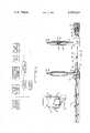
- FIG. 1is a perspective view of a hermetic compressor housing encircled by an electric heater assembly according to the present invention
- FIG. 2is a plan view of the heater assembly of FIG. 1 prior to being formed in a loop to encircle the housing;
- FIG. 3is a flow chart illustrating the process of fabricating the heater assembly of FIGS. 1 and 2.
- a hermetic compressor housing for a refrigeration type system of conventional designcontains a motor-compressor unit with refrigerant inlet and outlet tubes 13 and 15 as well as electrical leads 17 passing through the housing 11.
- a heating element 19encircles the housing in good heat transfer relation therewith.
- the heating elementis held tightly against the housing 11 by an elongated tensioning member 21 and electrical leads 23 and 25 extend from the heating element to be appropriately connected for heating the sump when desired.
- the details of the heater assemblywill be better understood by referring to FIG. 2.
- the sheathed tubular heating element 19contains one or more resistance wires 27 enclosed within an electrically insulating material 29 of a type which does not deteriorate at elevated temperatures.
- a metallic tubular sheath 31, typically of copper, aluminum or stainless steelsurrounds and protects the resistance wire 27 and insulation 29.
- the electrical leads 23 and 25are joined to the ends of the heating element by having their respective conductors, such as 33, welded, soldered or crimped to the corresponding resistance wire 27 and thereafter this junction is insulated, for example by molding insulating material 35 thereabout.
- Conductor 37 of lead 25is similarly connected to the heating element.
- a corrosion proof mechanical connectionis formed between heating element 19 and tensioning member 21 by forming an elbow bend 39 near one end of the selected heating element and then juxtaposing that bend with end 41 of the tensioning member and thereafter molding a mass 43 of non-metallic material about the element bend and a portion of the tensioning member to join the member to the selected element.
- This moldingmay be accomplished by injection molding techniques, for example in a simple rectangular cavity contoured in the parting plane on two adjacent sides of the rectangle to accept the metal clad heating element and on a third side generally in alignment with the direction of elongation of the main body of the heating element to accept end 41 of the tensioning member.
- One suitable molding compoundis polyphenylene sulfide, however, many other suitable materials are available.
- the other end of the tensioning member 21may similarly be connected to the other end of the heating element 19 as by the molded mass 45.
- the elongated tensioning member 21may comprise a pair of metal straps 47 and 49 of which strap 47 is provided with a series of slots while 49 may be unslotted but have crimped thereto a bracket 51 containing a hinged screw 53 which may be pivoted toward and away from strap 49 about the pivot axis 55.
- the screw 53has the same pitch as the separation between the slots in metal strap 47 so that the free end of strap 47 may be passed through bracket 51 between screw 53 and strap 49 and thereafter screw 53 pivoted toward strap 49 so that the screw threads engage the slots in strap 47 and thereater rotation of screw 53 will move one of the straps relative to the other to thereby effectively vary the length of the tensioning member and therefore also the circumference of the loop.
- the two strapsmay be molded to the heating element while the straps are separated and subsequently the straps joined to form the generally circular configuration of the heater assembly.
- the heater assemblyis then, of course, simply slipped over the canister, such as compressor housing 11, and the screw 53 tightened to tighten the loop about the housing.
- Certain of the process stepsshould be effected in a particular sequence, as illustrated by the solid connecting arrows in FIG. 3, while the particular stage in the process during which other of the steps are effected, is somewhat arbitrary, as illustrated by dotted arrow lines in FIG. 3.
- a heating element of appropriate length to nearly encircle the compressor housing and provide sufficient heater element extending beyond the connecting bends to allow the connection of lead wires 23 and 25is made.
- the heating elementshould be of sufficient length to contact most of the periphery of the canister and normally a heating element of a length approximately equal to the circumference of the housing is selected. This heater element length should be at least within one order of magnitude of the circumference of the housing.
- Bends near the element ends, such as 39,are next introduced into the heating element and thereafter that bend is positioned adjacent a tensioning member end to be joined thereto by molding the mass of non-magnetic material about both the elbow and the tensioning member end.
- the heating elementmay be formed into a partial loop to generally conform to the exterior of the compressor housing at any time after the particular heating element is selected, and similarly the attachment of wires 23 and 25 and the subsequent insulation of those lead wires junctions may be accomplished at any time during the process. Placing the heater assembly about the compressor housing and tightening the tension member to secure the heater assembly to the housing is normally the last step in the process.
Landscapes
- Compressor (AREA)
Abstract
Description
Claims (8)
Priority Applications (1)
| Application Number | Priority Date | Filing Date | Title |
|---|---|---|---|
| US06/176,109US4356624A (en) | 1980-08-07 | 1980-08-07 | Fabrication techniques for tubular sheathed heaters |
Applications Claiming Priority (1)
| Application Number | Priority Date | Filing Date | Title |
|---|---|---|---|
| US06/176,109US4356624A (en) | 1980-08-07 | 1980-08-07 | Fabrication techniques for tubular sheathed heaters |
Publications (1)
| Publication Number | Publication Date |
|---|---|
| US4356624Atrue US4356624A (en) | 1982-11-02 |
Family
ID=22643011
Family Applications (1)
| Application Number | Title | Priority Date | Filing Date |
|---|---|---|---|
| US06/176,109Expired - LifetimeUS4356624A (en) | 1980-08-07 | 1980-08-07 | Fabrication techniques for tubular sheathed heaters |
Country Status (1)
| Country | Link |
|---|---|
| US (1) | US4356624A (en) |
Cited By (5)
| Publication number | Priority date | Publication date | Assignee | Title |
|---|---|---|---|---|
| EP0165729A1 (en)* | 1984-05-31 | 1985-12-27 | Toyota Jidosha Kabushiki Kaisha | Device for tightening a coil on a cylindrical body |
| US4695712A (en)* | 1983-06-27 | 1987-09-22 | Metcal, Inc. | Flexible autoregulating heater with a latching mechanism |
| EP0248138A1 (en) | 1986-05-20 | 1987-12-09 | Jaquet Orthopedie S.A. | External dynamic bone fixation device |
| US20040256379A1 (en)* | 2003-06-18 | 2004-12-23 | Robert Kirby | Conduit ready electric belly-band heater and method of use |
| US11337761B2 (en) | 2019-02-07 | 2022-05-24 | Stryker European Operations Limited | Surgical systems and methods for facilitating tissue treatment |
Citations (6)
| Publication number | Priority date | Publication date | Assignee | Title |
|---|---|---|---|---|
| US3730373A (en)* | 1972-03-30 | 1973-05-01 | Emerson Electric Co | Band-type electric heaters |
| US3730262A (en)* | 1971-08-06 | 1973-05-01 | Emerson Electric Co | Heating and cooling units |
| US3873810A (en)* | 1974-03-15 | 1975-03-25 | Minnesota Mining & Mfg | Heater structure |
| US3887790A (en)* | 1974-10-07 | 1975-06-03 | Vernon H Ferguson | Wrap-around electric resistance heater |
| US3937870A (en)* | 1974-08-08 | 1976-02-10 | Clemar Manufacturing Corporation | Device for insulating an electrical wire joint |
| US4292503A (en)* | 1979-05-14 | 1981-09-29 | Emerson Electric Co. | Split-band electric heater |
- 1980
- 1980-08-07USUS06/176,109patent/US4356624A/ennot_activeExpired - Lifetime
Patent Citations (6)
| Publication number | Priority date | Publication date | Assignee | Title |
|---|---|---|---|---|
| US3730262A (en)* | 1971-08-06 | 1973-05-01 | Emerson Electric Co | Heating and cooling units |
| US3730373A (en)* | 1972-03-30 | 1973-05-01 | Emerson Electric Co | Band-type electric heaters |
| US3873810A (en)* | 1974-03-15 | 1975-03-25 | Minnesota Mining & Mfg | Heater structure |
| US3937870A (en)* | 1974-08-08 | 1976-02-10 | Clemar Manufacturing Corporation | Device for insulating an electrical wire joint |
| US3887790A (en)* | 1974-10-07 | 1975-06-03 | Vernon H Ferguson | Wrap-around electric resistance heater |
| US4292503A (en)* | 1979-05-14 | 1981-09-29 | Emerson Electric Co. | Split-band electric heater |
Cited By (9)
| Publication number | Priority date | Publication date | Assignee | Title |
|---|---|---|---|---|
| US4695712A (en)* | 1983-06-27 | 1987-09-22 | Metcal, Inc. | Flexible autoregulating heater with a latching mechanism |
| EP0165729A1 (en)* | 1984-05-31 | 1985-12-27 | Toyota Jidosha Kabushiki Kaisha | Device for tightening a coil on a cylindrical body |
| US4613296A (en)* | 1984-05-31 | 1986-09-23 | Toyota Jidosha Kabushiki Kaisha | Device for tightening a coil on a cylindrical body |
| US4636160A (en)* | 1984-05-31 | 1987-01-13 | Toyota Jidosha Kabushiki Kaisha | Device for tightening a coil on a cylindrical body |
| EP0248138A1 (en) | 1986-05-20 | 1987-12-09 | Jaquet Orthopedie S.A. | External dynamic bone fixation device |
| US20040256379A1 (en)* | 2003-06-18 | 2004-12-23 | Robert Kirby | Conduit ready electric belly-band heater and method of use |
| US6844531B2 (en)* | 2003-06-18 | 2005-01-18 | Tutco, Inc. | Conduit ready electric belly-band heater and method of use |
| US11337761B2 (en) | 2019-02-07 | 2022-05-24 | Stryker European Operations Limited | Surgical systems and methods for facilitating tissue treatment |
| US12137981B2 (en) | 2019-02-07 | 2024-11-12 | Stryker European Operations Limited | Surgical systems and methods for facilitating tissue treatment |
Similar Documents
| Publication | Publication Date | Title |
|---|---|---|
| JP5384942B2 (en) | Integral coupling mounting member | |
| US4401156A (en) | Heat transfer apparatus for releasably securing heating or cooling means to pipe | |
| CA1276661C (en) | Heat-insulated coupler for heatable flexible tubes | |
| AU719956B2 (en) | Method of attaching a connector to a coaxial cable and the resulting assembly | |
| US5586214A (en) | Immersion heating element with electric resistance heating material and polymeric layer disposed thereon | |
| EP0021597A2 (en) | Heat transfer apparatus for releasably securing heating or cooling means to pipe | |
| US4617456A (en) | Long life corrosion proof electroplating immersion heater | |
| CN101341632B (en) | Integral connecting device | |
| US4356624A (en) | Fabrication techniques for tubular sheathed heaters | |
| US2758150A (en) | Electrical connector for refrigerator defrosting means | |
| US3144507A (en) | Splint type reinforced conductor joint | |
| CA2875390C (en) | Silicone band cable heater assembly, method of making and method of use | |
| US9638438B2 (en) | Circulation heater | |
| US5687996A (en) | Molded part made of thermoplastic material | |
| US5953805A (en) | Magnet field concentrator for shaping metal parts | |
| JPH02183127A (en) | Thermocouple apparatus and manufacture thereof | |
| US4131788A (en) | Electric heater | |
| US4334726A (en) | Bonding device | |
| US6844531B2 (en) | Conduit ready electric belly-band heater and method of use | |
| US3369072A (en) | Cable termination | |
| US3395452A (en) | Methods of terminating electrical devices | |
| JP2003007152A (en) | Wire binding method | |
| US5614120A (en) | Sleeving for a wire used with a tail connected to a heating element and a method for heating | |
| JPH06260222A (en) | Superconducting conductor connection device | |
| KR880004156Y1 (en) | Earthing wire clamp |
Legal Events
| Date | Code | Title | Description |
|---|---|---|---|
| AS | Assignment | Owner name:LYALL ELECTRIC INC ALBION IND A CORP OF IND Free format text:ASSIGNMENT OF ASSIGNORS INTEREST.;ASSIGNORS:COVERSTONE, DON A.;HARRIS, LARRY G.;REEL/FRAME:004025/0619 Effective date:19800729 | |
| STCF | Information on status: patent grant | Free format text:PATENTED CASE | |
| AS | Assignment | Owner name:HEATERS ENGINEERING, INC., P.O. BOX 2000, KENDALLV Free format text:ASSIGNMENT OF ASSIGNORS INTEREST.;ASSIGNOR:LYALL ELECTRIC, INC.;REEL/FRAME:004746/0165 Effective date:19870804 Owner name:HEATERS ENGINEERING, INC., INDIANA Free format text:ASSIGNMENT OF ASSIGNORS INTEREST;ASSIGNOR:LYALL ELECTRIC, INC.;REEL/FRAME:004746/0165 Effective date:19870804 | |
| AS | Assignment | Owner name:M.A. INDUSTRIES, INC., GEORGIA Free format text:ASSIGNMENT OF ASSIGNORS INTEREST;ASSIGNOR:PIPE GASKET & SUPPLY CO., INC.;REEL/FRAME:008766/0569 Effective date:19970819 |