US4356358A - Membrane switch - Google Patents
Membrane switchDownload PDFInfo
- Publication number
- US4356358A US4356358AUS06/279,289US27928981AUS4356358AUS 4356358 AUS4356358 AUS 4356358AUS 27928981 AUS27928981 AUS 27928981AUS 4356358 AUS4356358 AUS 4356358A
- Authority
- US
- United States
- Prior art keywords
- switch
- sheet
- membrane switch
- electrodes
- tail
- Prior art date
- Legal status (The legal status is an assumption and is not a legal conclusion. Google has not performed a legal analysis and makes no representation as to the accuracy of the status listed.)
- Expired - Lifetime
Links
- 239000012528membraneSubstances0.000titleclaimsabstractdescription35
- 239000004020conductorSubstances0.000claimsabstractdescription34
- 238000003491arrayMethods0.000abstractdescription8
- 239000000976inkSubstances0.000description2
- 238000004519manufacturing processMethods0.000description2
- 229920002799BoPETPolymers0.000description1
- 239000005041Mylar™Substances0.000description1
- 230000003111delayed effectEffects0.000description1
- 229920002457flexible plasticPolymers0.000description1
- 230000007257malfunctionEffects0.000description1
- 239000000463materialSubstances0.000description1
- 238000000034methodMethods0.000description1
- 229920000728polyesterPolymers0.000description1
- 230000002028prematureEffects0.000description1
- 238000003825pressingMethods0.000description1
- 238000005476solderingMethods0.000description1
Images


Classifications
- H—ELECTRICITY
- H01—ELECTRIC ELEMENTS
- H01H—ELECTRIC SWITCHES; RELAYS; SELECTORS; EMERGENCY PROTECTIVE DEVICES
- H01H13/00—Switches having rectilinearly-movable operating part or parts adapted for pushing or pulling in one direction only, e.g. push-button switch
- H01H13/70—Switches having rectilinearly-movable operating part or parts adapted for pushing or pulling in one direction only, e.g. push-button switch having a plurality of operating members associated with different sets of contacts, e.g. keyboard
- H01H13/702—Switches having rectilinearly-movable operating part or parts adapted for pushing or pulling in one direction only, e.g. push-button switch having a plurality of operating members associated with different sets of contacts, e.g. keyboard with contacts carried by or formed from layers in a multilayer structure, e.g. membrane switches
- H—ELECTRICITY
- H01—ELECTRIC ELEMENTS
- H01H—ELECTRIC SWITCHES; RELAYS; SELECTORS; EMERGENCY PROTECTIVE DEVICES
- H01H2207/00—Connections
- H01H2207/004—Printed circuit tail
- H—ELECTRICITY
- H01—ELECTRIC ELEMENTS
- H01H—ELECTRIC SWITCHES; RELAYS; SELECTORS; EMERGENCY PROTECTIVE DEVICES
- H01H2229/00—Manufacturing
- H01H2229/038—Folding of flexible printed circuit
Definitions
- This inventionrelates to membrane switch devices of the type comprising a sheet of insulating film which has been folded about a medial fold line and which has switch electrodes and conductors on the opposed surfaces so that a circuit can be completed by flexing the film and moving two electrodes against each other.
- the inventionis particularly directed to a membrane switch device having two separate switch arrays in parallel relationship to each other.
- U.S. Pat. No. 4,066,851describes a membrane switch device comprising a rectangular sheet of insulating film which has been folded about a medial fold line so that it has opposed surfaces on which switch electrodes and switch conductors are provided. A separator is positioned between the surfaces and an individual circuit can be completed by pressing on the film to move the desired electrodes towards each other and close a predetermined circuit.
- U.S. Pat. No. 4,066,851describes a convenient manufacturing method for producing membrane switches.
- the switch electrodes and the switch conductorsare formed, as by printing a conductive ink, on one surface of a flexible film.
- the filmis then folded along a medial fold line so that two surfaces are opposed to each other, the opposed surfaces having the conductors and electrodes thereon.
- the conductors on the filmusually extend to a tail and can be connected from this tail to further circuit conductors by means of a connector or by soldering.
- membrane switchesit is sometimes desirable to use membrane switches as double-pole, double-break switches so that when an individual switch site is pressed, two electrical circuits are completed as shown in U.S. Pat. No. 3,917,917.
- the double-pole, double-break switches of the 3,917,917 patentare formed by use of three individual insulating films which must be assembled to each other by suitable fasteners, such as screws or rivets, to form the assembly.
- the present inventionis directed to the achievement of a membrane switch device having individual double-pole, switches which is produced by silkscreening or otherwise applying conductors to one surface of a film and thereafter folding the film to produce the completed switch.
- a membrane switch device in accordance with the inventionis produced by applying to one surface of an elongated sheet of insulating film all of the switch conductors and switch electrodes required for two individual switch arrays.
- the conductorsextend to a tail by means of which they can be connected to further circuit conductors.
- the elongated sheet of filmis then folded along a first fold line which is adjacent to the tail and the tail is inserted through a slit in the film, the slit being midway between the ends of the elongated sheet of film.
- This first folding operationproduces a first array of membrane switch sites.
- the remaining section of the filmis also folded along a fold line to produce the second array of membrane switch sites and this second array is then folded as a unit so that it is parallel to the first array.
- Suitable separatorsare provided between the opposed surfaces of the film in the first array and in the second array.
- the switch sites in the two arraysare located such that after all of the folding operations have been carried out, the switch sites in the first array and in the second array are in alignment with each other.
- the electrodes in the first array and in the second arrayare moved towards each other so that two circuits are completed by the single switch closing operation.
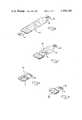
- FIGS. 1-4show an elongated sheet of insulating film having conductors on one surface thereof, this film being folded as shown in FIGS. 2 and 3 to produce a membrane switch device as shown in FIG. 4.
- FIG. 5is a plan view showing the location of the electrodes and conductors and the fold lines of the film.
- FIG. 6is a view similar to FIG. 1 showing a sheet of film used to produce an alternative embodiment.
- FIGS. 7 and 8illustrate the folding of the film shown in FIG. 6.
- FIG. 9is a perspective view of the alternative embodiment.
- a switch device 2in accordance with the invention, comprises two switch arrays 3, 6 which are folded against each other, as will be described below.
- the completed switch device 2has a tail 4 extending from one of its edges and the conductors on the switch extend onto this tail as shown at 5, so that the switch electrodes and switch conductors can be connected to external circuitry.
- the conductors 5may be soldered to further conductors or may be connected by means of a suitable electrical connector.
- the structure of the switch device 2is best understood from an explanation of the manner in which the completed device is produced from an elongated sheet of insulating film 9 which is shown in FIG. 5.
- the filmmay be of any suitable flexible plastic material, such as Mylar (polyester) and can be considered as comprised of two generally rectangular sections 10, 10' which are separated by a slit 16.
- the section 10has parallel side edges 12, an end edge 14 from which the tail 4 extends, and an opposite end which is defined by the slit 16.
- the side edgesare also notched at 18 in the vicinity of the slit 16 to facilitate folding, as will be described below.
- Conductors and electrodesare provided on the upper surface or first surface, as viewed in FIGS. 1 and 5, by silkscreening or otherwise printing conductive inks. Alternatively, these conductors may be electrodeposited by known techniques for producing electrodeposited conductors and switch electrodes on surfaces of films.
- a first plurality of switch electrodes 22 and switch conductors 26are provided on the surface 20 to the right of a fold line 32.
- a second plurality of switch electrodes 24 and switch conductors 28are provided on the other side of the fold line 32 adjacent to the tail 4, the electrodes 22 and 24 being so located that when the section 10 is folded at the fold line 32, each electrode 24 will be opposed to, and in alignment with, an electrode 22.
- the fold line 32is defined by a slit in the film and by notches 30 in the side edges 12 and folding is carried out by simply folding the lefthand section, as viewed in FIG. 5, towards the righthand section so that the two sections have opposed surfaces on which the conductors are formed.
- the tail 4is inserted through the slit 16 when this initial folding operation is carried out so that it extends beneath the remaining portion 10' of the film, see FIG. 2.
- a separator 34is positioned between the opposed surfaces of the switch array 3 and has openings 36 therein which are in alignment with the electrodes 22, 24 to permit closing of the individual switches at the switch sites.
- the portion 10' of the elongated sheet 9is in many respects similar to the portion 10 and is folded about a fold line defined by a slit 32' and notches 30' in the side edges 12'.
- the portion 10'has electrodes 24' which are on the righthand side of the fold line 32' and electrodes 22' on the lefthand side of this fold line. Conductors for the electrodes are also shown at 26' and 28'.
- the electrodes 22', 24'are opposed to each other after this second folding operation is carried out so that corresponding pairs of electrodes define an individual switch.
- a separator 34'is also positioned between the surfaces of the second or additional switch device 6 when the folding operation is carried out on the section 10'.
- the switch device 6is folded as a unit towards the switch device 3 so that the two switch arrays are now against each other in parallel relationship with the tail 4 extending from the slit 16 which defines one of the side edges of the switch device 2.
- all of the conductors 26, 28, 26', 28'extend across the fold lines on internal surfaces so that these conductors are never placed in tension as the result of the folding operation. This feature is of importance where the conductors are extremely thin and fragile, since they can be damaged if folded in a manner such that they are placed in tension.
- FIG. 9shows an alternative embodiment having a second tail 40 extending from the switch device 38.
- the embodiment of FIG. 9is produced generally as described above, but from a strip having a tail 40 extending from the end edge 14' thereof.
- the tail 40is inserted through the slit 16 when the section 10' is folded, as described above, so that the tail 40 will be adjacent to and parallel to the tail 4.
- the conductors on the two tails 4, and 40will be on the exposed surfaces which face in opposite directions so that connections can then be made to these conductors with a two row electrical connector, if desired.
- the switch device 2will ordinarily be contained in a suitable housing which may have graphics thereon above the individual switch position.
- the housingmay have separate switch keys therein which, when pressed, close predetermined switches in the two switch arrays.
- a double-pole switch device produced in accordance with the inventionmay be used for a wide variety of circuits and the particular circuits shown in FIG. 5 represent but one application and use of the principles of the invention.
- the particular circuits shown in FIG. 5are used in a binary coded device and are advantageous in that malfunction is prevented as a result of the time delay between closing of two switches in the device.
- the circuit shownis arranged such that the input to the switch device produced when pressure is applied to one of the switch sites is delayed until both of the membrane switches at the switch site are closed. This prevents premature flow of input which might lead to operation of the circuitry in an unintended manner.
Landscapes
- Push-Button Switches (AREA)
Abstract
Description
Claims (8)
Priority Applications (1)
| Application Number | Priority Date | Filing Date | Title |
|---|---|---|---|
| US06/279,289US4356358A (en) | 1981-07-01 | 1981-07-01 | Membrane switch |
Applications Claiming Priority (1)
| Application Number | Priority Date | Filing Date | Title |
|---|---|---|---|
| US06/279,289US4356358A (en) | 1981-07-01 | 1981-07-01 | Membrane switch |
Publications (1)
| Publication Number | Publication Date |
|---|---|
| US4356358Atrue US4356358A (en) | 1982-10-26 |
Family
ID=23068358
Family Applications (1)
| Application Number | Title | Priority Date | Filing Date |
|---|---|---|---|
| US06/279,289Expired - LifetimeUS4356358A (en) | 1981-07-01 | 1981-07-01 | Membrane switch |
Country Status (1)
| Country | Link |
|---|---|
| US (1) | US4356358A (en) |
Cited By (15)
| Publication number | Priority date | Publication date | Assignee | Title |
|---|---|---|---|---|
| US4425484A (en) | 1981-07-23 | 1984-01-10 | Amp Incorporated | Encoded keyboard switch |
| GB2124031A (en)* | 1982-07-06 | 1984-02-08 | Jaeger | Electric contact device |
| WO1984000847A1 (en)* | 1982-08-13 | 1984-03-01 | Press On Inc | Enlarged switch area membrane switch and method |
| US4450324A (en)* | 1983-06-08 | 1984-05-22 | Amp Incorporated | Encoded keyboard switch |
| US4484039A (en)* | 1983-08-29 | 1984-11-20 | Amp Incorporated | Membrane switch having improved switch tail |
| US4493952A (en)* | 1983-08-29 | 1985-01-15 | Amp Incorporated | Membrane switch having integral switch tail insulator |
| JPS6098232U (en)* | 1983-12-10 | 1985-07-04 | アルプス電気株式会社 | membrane switch |
| USD285921S (en) | 1984-01-04 | 1986-09-30 | International Standard Electric Corporation | Telephone set |
| US4659879A (en)* | 1985-03-11 | 1987-04-21 | Topre Corporation | Key switch |
| US4730146A (en)* | 1986-10-21 | 1988-03-08 | W. H. Brady Co. | Folded electroluminescent lamp assembly |
| US4837412A (en)* | 1987-06-29 | 1989-06-06 | Oki Electric Industry Co., Ltd. | Keyboard of a membrane contact type |
| US5356296A (en)* | 1992-07-08 | 1994-10-18 | Harold D. Pierce | Audio storybook |
| US20140120799A1 (en)* | 2012-10-31 | 2014-05-01 | Leo Paper Bags Manufacturing (1982) Limited | Interactive puzzle book assembly |
| EP2775498A1 (en)* | 2013-03-06 | 2014-09-10 | Ricoh Company Ltd. | Wide-area pressure sensor with reduced power consumption |
| US20140260753A1 (en)* | 2013-03-15 | 2014-09-18 | Rti Sports Vertrieb Von Sportartikeln Gmbh | Bicycle handle system |
Citations (6)
| Publication number | Priority date | Publication date | Assignee | Title |
|---|---|---|---|---|
| US3987259A (en)* | 1975-06-12 | 1976-10-19 | Globe-Union Inc. | Membrane switch apparatus having sequential bridging contact arrangement |
| US3996427A (en)* | 1975-01-10 | 1976-12-07 | Texas Instruments Incorporated | Pushbutton keyboard system and method of making same |
| US3996429A (en)* | 1975-04-18 | 1976-12-07 | Northern Electric Company Limited | Multi-contact push-button switch having plural prestressed contact members designed to provide plural circuit simultaneous switching inputs |
| US4066851A (en)* | 1975-10-30 | 1978-01-03 | Chomerics, Inc. | Keyboard switch assembly having foldable printed circuit board, integral spacer and preformed depression-type alignment fold |
| US4246452A (en)* | 1979-01-05 | 1981-01-20 | Mattel, Inc. | Switch apparatus |
| US4284866A (en)* | 1980-08-25 | 1981-08-18 | Amp Incorporated | Membrane switch assembly |
- 1981
- 1981-07-01USUS06/279,289patent/US4356358A/ennot_activeExpired - Lifetime
Patent Citations (6)
| Publication number | Priority date | Publication date | Assignee | Title |
|---|---|---|---|---|
| US3996427A (en)* | 1975-01-10 | 1976-12-07 | Texas Instruments Incorporated | Pushbutton keyboard system and method of making same |
| US3996429A (en)* | 1975-04-18 | 1976-12-07 | Northern Electric Company Limited | Multi-contact push-button switch having plural prestressed contact members designed to provide plural circuit simultaneous switching inputs |
| US3987259A (en)* | 1975-06-12 | 1976-10-19 | Globe-Union Inc. | Membrane switch apparatus having sequential bridging contact arrangement |
| US4066851A (en)* | 1975-10-30 | 1978-01-03 | Chomerics, Inc. | Keyboard switch assembly having foldable printed circuit board, integral spacer and preformed depression-type alignment fold |
| US4246452A (en)* | 1979-01-05 | 1981-01-20 | Mattel, Inc. | Switch apparatus |
| US4284866A (en)* | 1980-08-25 | 1981-08-18 | Amp Incorporated | Membrane switch assembly |
Cited By (19)
| Publication number | Priority date | Publication date | Assignee | Title |
|---|---|---|---|---|
| US4425484A (en) | 1981-07-23 | 1984-01-10 | Amp Incorporated | Encoded keyboard switch |
| GB2124031A (en)* | 1982-07-06 | 1984-02-08 | Jaeger | Electric contact device |
| WO1984000847A1 (en)* | 1982-08-13 | 1984-03-01 | Press On Inc | Enlarged switch area membrane switch and method |
| US4471177A (en)* | 1982-08-13 | 1984-09-11 | Press On, Inc. | Enlarged switch area membrane switch and method |
| US4450324A (en)* | 1983-06-08 | 1984-05-22 | Amp Incorporated | Encoded keyboard switch |
| US4484039A (en)* | 1983-08-29 | 1984-11-20 | Amp Incorporated | Membrane switch having improved switch tail |
| US4493952A (en)* | 1983-08-29 | 1985-01-15 | Amp Incorporated | Membrane switch having integral switch tail insulator |
| JPS6098232U (en)* | 1983-12-10 | 1985-07-04 | アルプス電気株式会社 | membrane switch |
| USD285921S (en) | 1984-01-04 | 1986-09-30 | International Standard Electric Corporation | Telephone set |
| US4659879A (en)* | 1985-03-11 | 1987-04-21 | Topre Corporation | Key switch |
| US4730146A (en)* | 1986-10-21 | 1988-03-08 | W. H. Brady Co. | Folded electroluminescent lamp assembly |
| US4837412A (en)* | 1987-06-29 | 1989-06-06 | Oki Electric Industry Co., Ltd. | Keyboard of a membrane contact type |
| US5356296A (en)* | 1992-07-08 | 1994-10-18 | Harold D. Pierce | Audio storybook |
| US20140120799A1 (en)* | 2012-10-31 | 2014-05-01 | Leo Paper Bags Manufacturing (1982) Limited | Interactive puzzle book assembly |
| US9311822B2 (en)* | 2012-10-31 | 2016-04-12 | Leo Paper Bags Manufacturing (1982) Limited | Interactive puzzle book assembly |
| EP2775498A1 (en)* | 2013-03-06 | 2014-09-10 | Ricoh Company Ltd. | Wide-area pressure sensor with reduced power consumption |
| US9127992B2 (en) | 2013-03-06 | 2015-09-08 | Ricoh Company, Ltd. | Wide-area pressure sensor with reduced power consumption |
| US20140260753A1 (en)* | 2013-03-15 | 2014-09-18 | Rti Sports Vertrieb Von Sportartikeln Gmbh | Bicycle handle system |
| US9287063B2 (en)* | 2013-03-15 | 2016-03-15 | Rti Sports Vertrieb Von Sportartikeln Gmbh | Bicycle handle system |
Similar Documents
| Publication | Publication Date | Title |
|---|---|---|
| US4356358A (en) | Membrane switch | |
| US4199209A (en) | Electrical interconnecting device | |
| US4603928A (en) | Board to board edge connector | |
| US5161981A (en) | Foldable stacking connector | |
| US4403272A (en) | Membrane switch interconnect tail and printed circuit board connection | |
| US3805213A (en) | Flexible circuit connectors | |
| US3673357A (en) | Tactile response switch with unitary control strip of independently operably plural disc contacts | |
| US3994554A (en) | Flat conductor flat cable adapter | |
| US4085998A (en) | Dual clip connector | |
| JPH0615273B2 (en) | IC card | |
| DE2551761A1 (en) | PUSH KEYPAD | |
| JPH0256903A (en) | Variable resistance device | |
| US5061830A (en) | Extension electrical switch system and method of manufacture | |
| KR970076913A (en) | Resistor and manufacturing method | |
| US3362005A (en) | Hinge type connector for circuit boards | |
| US4913662A (en) | Flat, flexible, cable construction and connector attached thereto | |
| US4677529A (en) | Circuit board | |
| US4113342A (en) | Conductor arrangement and assembly method | |
| KR900005511A (en) | Sheet Switch | |
| US4658104A (en) | Printed wiring board | |
| US4425484A (en) | Encoded keyboard switch | |
| US4364619A (en) | Interconnection system for printed circuit board devices | |
| US4484039A (en) | Membrane switch having improved switch tail | |
| US4392181A (en) | Circuit board and contact assemblies | |
| EP0147045A2 (en) | Membrane type circuit having improved tail |
Legal Events
| Date | Code | Title | Description |
|---|---|---|---|
| AS | Assignment | Owner name:AMP INCORPORATED; 3705 PAXTON ST., HARRISBURG, PA. Free format text:ASSIGNMENT OF ASSIGNORS INTEREST.;ASSIGNOR:FUKUKURA, KAZUTOYO;REEL/FRAME:003898/0873 Effective date:19810624 | |
| STCF | Information on status: patent grant | Free format text:PATENTED CASE | |
| FEPP | Fee payment procedure | Free format text:SURCHARGE FOR LATE PAYMENT, PL 96-517 (ORIGINAL EVENT CODE: M176); ENTITY STATUS OF PATENT OWNER: LARGE ENTITY | |
| MAFP | Maintenance fee payment | Free format text:PAYMENT OF MAINTENANCE FEE, 4TH YEAR, PL 96-517 (ORIGINAL EVENT CODE: M170); ENTITY STATUS OF PATENT OWNER: LARGE ENTITY Year of fee payment:4 | |
| FEPP | Fee payment procedure | Free format text:MAINTENANCE FEE REMINDER MAILED (ORIGINAL EVENT CODE: REM.); ENTITY STATUS OF PATENT OWNER: LARGE ENTITY | |
| AS | Assignment | Owner name:LUCAS DURALITH AKT CORPORATION Free format text:CHANGE OF NAME;ASSIGNOR:AMP KEYBOARD TECHNOLOGIES INC.;REEL/FRAME:005258/0527 Effective date:19890428 Owner name:AMP KEYBOARD TECHNOLOGIES, INC., A WHOLLY OWNED SU Free format text:ASSIGNMENT OF ASSIGNORS INTEREST.;ASSIGNOR:AMP INCORPORATED;REEL/FRAME:005258/0518 Effective date:19890418 | |
| MAFP | Maintenance fee payment | Free format text:PAYMENT OF MAINTENANCE FEE, 8TH YEAR, PL 96-517 (ORIGINAL EVENT CODE: M171); ENTITY STATUS OF PATENT OWNER: LARGE ENTITY Year of fee payment:8 | |
| FEPP | Fee payment procedure | Free format text:PAYOR NUMBER ASSIGNED (ORIGINAL EVENT CODE: ASPN); ENTITY STATUS OF PATENT OWNER: LARGE ENTITY | |
| FEPP | Fee payment procedure | Free format text:PAYMENT IS IN EXCESS OF AMOUNT REQUIRED. REFUND SCHEDULED (ORIGINAL EVENT CODE: F169); ENTITY STATUS OF PATENT OWNER: LARGE ENTITY | |
| REFU | Refund | Free format text:REFUND - PAYMENT OF MAINTENANCE FEE, 8TH YEAR, PL 96-517 (ORIGINAL EVENT CODE: R171); ENTITY STATUS OF PATENT OWNER: LARGE ENTITY | |
| MAFP | Maintenance fee payment | Free format text:PAYMENT OF MAINTENANCE FEE, 12TH YEAR, LARGE ENTITY (ORIGINAL EVENT CODE: M185); ENTITY STATUS OF PATENT OWNER: LARGE ENTITY Year of fee payment:12 |