US4356073A - Magnetron cathode sputtering apparatus - Google Patents
Magnetron cathode sputtering apparatusDownload PDFInfo
- Publication number
- US4356073A US4356073AUS06/233,974US23397481AUS4356073AUS 4356073 AUS4356073 AUS 4356073AUS 23397481 AUS23397481 AUS 23397481AUS 4356073 AUS4356073 AUS 4356073A
- Authority
- US
- United States
- Prior art keywords
- tube
- magnets
- magnetic
- conduit
- tubular member
- Prior art date
- Legal status (The legal status is an assumption and is not a legal conclusion. Google has not performed a legal analysis and makes no representation as to the accuracy of the status listed.)
- Expired - Lifetime
Links
- 238000004544sputter depositionMethods0.000titleclaimsabstractdescription20
- 239000011248coating agentSubstances0.000claimsabstractdescription51
- 238000000576coating methodMethods0.000claimsabstractdescription51
- 239000000463materialSubstances0.000claimsabstractdescription38
- 239000000758substrateSubstances0.000claimsabstractdescription13
- 239000000110cooling liquidSubstances0.000claimsdescription7
- 230000003628erosive effectEffects0.000claimsdescription6
- 239000010409thin filmSubstances0.000claimsdescription4
- 238000000034methodMethods0.000claimsdescription3
- 238000007599dischargingMethods0.000claims3
- 238000001816coolingMethods0.000abstractdescription2
- 239000013077target materialSubstances0.000description7
- 239000002826coolantSubstances0.000description5
- 238000000429assemblyMethods0.000description3
- 230000000712assemblyEffects0.000description3
- 238000000151depositionMethods0.000description3
- 239000000696magnetic materialSubstances0.000description3
- 230000008021depositionEffects0.000description2
- 239000007789gasSubstances0.000description2
- XLYOFNOQVPJJNP-UHFFFAOYSA-NwaterSubstancesOXLYOFNOQVPJJNP-UHFFFAOYSA-N0.000description2
- 229910001369BrassInorganic materials0.000description1
- 229910001209Low-carbon steelInorganic materials0.000description1
- 239000010951brassSubstances0.000description1
- 238000010276constructionMethods0.000description1
- -1for exampleSubstances0.000description1
- 238000012986modificationMethods0.000description1
- 230000004048modificationEffects0.000description1
- 239000002245particleSubstances0.000description1
- 229910001220stainless steelInorganic materials0.000description1
- 239000010935stainless steelSubstances0.000description1
Images

Classifications
- H—ELECTRICITY
- H01—ELECTRIC ELEMENTS
- H01J—ELECTRIC DISCHARGE TUBES OR DISCHARGE LAMPS
- H01J37/00—Discharge tubes with provision for introducing objects or material to be exposed to the discharge, e.g. for the purpose of examination or processing thereof
- H01J37/32—Gas-filled discharge tubes
- H01J37/34—Gas-filled discharge tubes operating with cathodic sputtering
- H01J37/3402—Gas-filled discharge tubes operating with cathodic sputtering using supplementary magnetic fields
- H01J37/3405—Magnetron sputtering
Definitions
- the present inventioncontemplates a new and novel form of magnetron cathode which is significantly different from the planar magnetron cathodes heretofore proposed and which, while retaining the advantages of high deposition rates, also renders possible an even more effective and maximum utilization of the target material thereby substantially increasing the operating life thereof.
- the cathode assemblycomprises an elongated, cylindrical rotatable tube having a layer of the target material to be sputtered applied to the outer surface thereof.
- Magnetic meansincluding an array of U-shaped permanent magnets is arranged inside the tube, with the opposite legs of the magnets being secured to spaced, parallel magnetic strips running lengthwise of the tube.
- the tubeis rotatable about its longitudinal axis so that it can be turned relative to the magnets to selectively bring different portions or segments of the target material on the outer surface thereof into position opposite the magnets and within the magnetic field. Also different coating materials can be applied to different portions of the outer surface of the rotatable tube so that by turning the tube a particular selected coating material can be brought into sputtering position.
- the cathode assemblyis internally cooled by the circulation of a cooling liquid therethrough.
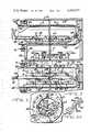
- FIG. 2is a horizontal longitudinal section taken substantially on line 2--2 of FIG. 1,
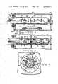
- FIG. 3is an end view of FIG. 1,
- FIG. 3Ais a perspective view of a portion of one of the magnetic strips
- FIG. 5is a horizontal longitudinal section taken substantially on line 5--5 of FIG. 4,
- FIGS. 7 and 8are generally schematic plan views illustrating two other modified forms of the invention.
- the cathode assemblyis designated by the numeral 20 and is mounted in an evacuable coating chamber 21.
- the coating chamberis rectangular and is composed of a bottom wall 22, top wall 23, opposite side walls 24 and 25 and end walls (not shown)
- the bottom and top walls 22 and 23are suitably joined to the side walls 24 and 25 at the hermetic seals 26 and 27 respectively.
- the end wallsare similarly sealed to the top and bottom and side walls.
- a vacuum pump 28is provided to evacuate the coating chamber 21 to the desired pressure. Should it be desired to inject gases into the chamber, it may be done through conduit 29 controlled by a valve 30.
- the cathode assembly 20comprises generally an elongated cylindrical tube 31 mounted in the coating chamber 21 and in the lower portion of which is mounted the magnetic means 32.
- the tube 31is formed of a suitable non-magnetic material such as, for example, brass or stainless steel and is of a diameter, wall thickness and length required for the operation to be performed.
- a layer 33 of a selected coating or target material to be deposited onto the substrates being coatedis a layer 33 of a selected coating or target material to be deposited onto the substrates being coated.
- the tube 31 and layer of coating material 33constitute a tubular target or sputtering source as distinguished from the conventional planar target.
- the tube 31is supported in a horizontal position in the coating chamber 21 and is mounted for rotation about its longitudinal axis.
- the tubeis supported at its inner end by a trunnion 34 secured to the closed inner end 35 of the tube and journaled in a bearing block 36 carried by a bracket 37 secured to the side wall 25 of the coating chamber by screws 38.
- the tube 31is open at its outer end and extends through an opening in the side wall 24 of the coating chamber 21, where it is supported in an annular ring 39 surrounded by a collar 40 secured to said side wall 24 by screws 41.
- the interior of the coating chamberis sealed from the atmosphere by O-rings 42 and 43 engaging the tube 31 and side wall 24 of the coating chamber respectively.
- a coolant conduit 44also of a suitable non-magnetic material extending longitudinally in the lower portion of the tube 31.
- the inner end of said conduitis closed and spaced from the closed inner end 35 of tube 31, while the outer end thereof extends beyond the tube as indicated at 45.
- a suitable coolantsuch as water, is introduced into the outer end of the conduit 44 and, after passing through openings 46 therein, circulates throughout the tube 31 and exits at the outer end thereof.
- the magnetic means 32comprises an array of U-shaped permanent magnets 47 arranged in two straight parallel rows A and B that extend lengthwise within the tube 31.
- the magnets 47 in each roware aligned with one another, with the magnets in one row being disposed alternately with and overlapping the magnets in the other row. Also the magnets in the two rows A and B are arranged at an angle relative to one another, as shown in FIG. 3, and are secured to the conduit 44 by suitable brackets or the like.
- the outer legs 48 of the magnets 47 in row Aengage a longitudinally extending, relative narrow strip 49 of a suitable magnetic material, such as hot rolled mild steel, while the outer legs 50 of the magnets in row B engage a similar magnetic strip 51 arranged parallel with magnetic strip 49.
- the inner legs 52 and 53 of the magnets in rows A and Boverlap one another and engage a central longitudinally extending magnetic strip 54 that extends parallel with the outer magnetic strips 49 and 51.
- the magnets 47are secured to the respective magnetic strips by screws 55 passing therethrough to tie them together as a unit.
- the bottom surfaces 59 of the magnetic strips 49, 51 and 54are shaped to conform to the curvature of the inner surface of the tube 31.
- the central magnetic strip 54is notched on a slant alternately first to one side and then the other, as indicated at 54a in FIG. 3A, such that the inner legs 52 and 53 of the magnets will make fiace-to-face contact with said strip.
- the magnets 47are preferably disposed so that the north poles thereof engage the outer magnetic strips 49 and 51, while the south poles of the magnets engage the central magnetic strip 54. This arrangement of the magnets and magnetic strips establishes two straight magnetic fields along which erosion of the target material 33 takes place.
- a cathode potential sufficient to cause sputtering to occuris supplied to the tubular target from a D.C. power source (not shown) through a power line 60 having sliding contact with the tube 31.
- the apparatusis grounded in any suitable manner.
- the Substantially Planar substrates S to be coatedare supported on and carried through the coating chamber 21 and beneath the cathode 20 by rollers 62 and 63 keyed to a horizontal shaft 64 journaled in bearing blocks 65 and 65a supported on the bottom of the coating chamber.
- the outer surface of the tube 31is provided with a layer 33 of the material to be sputtered on the substrates S as they pass therebeneath.
- the tubeBy means of the handle 66 secured to the outer end of the tube 31 the tube can be rotated either clockwise or counter-clockwise about its longitudinal axis to position a selected portion of the coating material to be sputtered directly opposite the magnets and within the magnetic field. When this portion of the coating material has been depleted, the tube can again be rotated to bring another and fresh portion of the coating material into sputtering position. This procedure can be repeated until a maximum amount of the coating material has been utilized.
- a particular selected coating materialcan be brought into sputtering position. In this way, it is possible to sputter different coating materials onto the substrates from a single target.
- the magnetic means 32are supported on the tube 31, with the magnetic strips 49, 51 and 54 in direct contact with the inner surface thereof.
- the magnetsmay be moved slightly with the tube from their original position relative to that portion of the coating material to be sputtered. Should this occur, it can be readily corrected and the magnets returned to their original position by turning the conduit 44, by mans of the handle 67 secured to the outer end thereof, to move the magnets in the reverse direction.
- FIGS. 4, 5 and 6are views similar to FIGS. 1, 2 and 3 respectively but disclose an alternate form of magnetic means 70. Otherwise, the construction and operation of the apparatus are the same as above described with reference to FIGS. 1, 2 and 3 and the same numerals are used to designate like parts.
- the magnetic means 70is composed of a single row C of permanent U-shaped magnets 71, the legs 72 and 73 of which engage spaced, longitudinally extending magnetic strips 74 and 75 respectively and are secured thereto by screws 76 and 77.
- the bottom surfaces 78 and 79 of the magnetic strips 74 and 75are shaped to conform to the curvature of the inner surface of the tube 31.
- the established magnetic fieldalso follows a straight path to create a straight erosion pattern on the target material.
- a coolant conduit 80Extending longitudinally within the tube 31 and beneath the row of magnets 71 is a coolant conduit 80 to which the magnets are secured.
- a cooling liquidsuch as water, is introduced into the outer end of the conduit and discharged therefrom through openings 81 into the tube. The cooling liquid, after circulating within the tube 31, exits therefrom through the outer end thereof.
- the tube 31can also be rotated by means of the handle 66 to selectively position different portions of the coating material opposite the magnets and within the magnetic field. Likewise, after the tube has been turned to place the selected unused portion of the coating material in sputtering position, the magnetic means can be adjusted, if necessary, by means of the handle 67 to again bring the magnets into proper position relative to that portion of the coating material to be sputtered.
- FIGS. 7 and 8are illustrated in somewhat schematic form two other modified embodiments of the invention, in each of which a plurality of rotatable cathodes of the type shown in FIGS. 4, 5 and 6 are employed.
- each cathode assemblycomprises an elongated, cylindrical tube 85 mounted for rotation in the opposite side walls of the coating chamber 84 and having a layer of the coating material 85a to be sputtered applied to the outer surface thereof.
- the magnetic means 86composed of a single row of permanent U-shaped magnets 87, the opposite legs of which engage longitudinally extending magnetic strips 88 and 89 and are secured thereto by screws 90 and 91 respectively.
- each cathode assemblyconstitutes the north pole piece and the inner magnetic strip 89 the south pole piece.
- the outer magnetic strips 88extend beyond the inner magnetic strips 89 and are turned inwardly toward one another as indicated at 92.
- Positioned between the cathodes 82 and 83 at the opposite ends thereofare the additional permanent U-shaped magnets 93 and 94 which bridge the gap between the inturned ends 92 of the magnetic strips 88 and in conjunction therewith establish a magnetic field in the form of a closed loop or race track.
- the cathodes 82 and 83are internally cooled by the introduction of a cooling liquid into the coolant conduits 95 as above described with reference to FIGS. 1, 2 and 3.
- the tubes 85 of the cathodes 82 and 83are rotatable independently of one another to bring the desired unused portion of the coating material on the outer surface thereof into proper registration with the respective row of magnets. Either the same or different types of coating materials can be applied to the tubes.
- cathode assemblies 96, 97, 98 and 99are mounted in horizontally spaced, parallel relation in the coating chamber 100.
- These cathode assembliesare preferably of the same type as shown in FIG. 7, with each comprising an elongated, cylindrical rotatable tube 101 having a layer of the material to be sputtered applied to the outer surface thereof.
- the magnetic means with the tube 85 of each cathodeis composed of a single row of permanent U-shaped magnets 102, the opposite legs of which engage and are secured to the magnetic strips 103 and 104 by screws 105 and 106 respectively.
- the magnetic strips 103constitute north pole pieces, while the magnetic strips 104 constitute south pole pieces.
- the magnetic strips 103 of cathodes 96-97 and 98-99extend at one end beyond the associated strips 104 and are turned inwardly as indicated at 107 and 108 respectively.
- the magnetic strips 104 of the magnets 97 and 98extend beyond the associated magnetic strips 103 at the other end of the rows of magnets and are turned inwardly toward one another as indicated at 109.
- a permenent U-shaped magnet 110Located between the inturned ends 107 of magnetic strips 103 of cathodes 96 and 97 is a permenent U-shaped magnet 110 and a similar magnet 111 is positioned between the inturned ends 108 of the magnetic strips 103 of cathodes 98 and 99. Also positioned between the inturned ends 109 of the magnetic strips 104 of magnets 97 and 98 is a like permenent magnet 112.
- the individual magnets 110, 111 and 112 at the opposite ends of the cathodesserve to bridge the gaps between the associated magnetic strips and in conjunction therewith act to complete the magnetic field which follows a serpentine path from cathode 96 to cathode 99.
- the tubes 101 of the cathodes 96, 97, 98 and 99are mounted in the coating chamber 100 for individual rotation relative to one another and may be provided with the same or different types of coating materials.
- the cathodesare also adapted to be internally cooled as described above through the coolant conduits 113, 114, 115 and 116 to which the associated magnets 102 are secured.
Landscapes
- Physics & Mathematics (AREA)
- Engineering & Computer Science (AREA)
- Plasma & Fusion (AREA)
- Chemical & Material Sciences (AREA)
- Analytical Chemistry (AREA)
- Physical Vapour Deposition (AREA)
- Macromonomer-Based Addition Polymer (AREA)
- Silicon Polymers (AREA)
Abstract
Description
Claims (12)
Priority Applications (20)
| Application Number | Priority Date | Filing Date | Title |
|---|---|---|---|
| US06/233,974US4356073A (en) | 1981-02-12 | 1981-02-12 | Magnetron cathode sputtering apparatus |
| PCT/US1982/000171WO1982002725A1 (en) | 1981-02-12 | 1982-02-11 | Magnetron cathode sputtering apparatus |
| MX191341AMX151747A (en) | 1981-02-12 | 1982-02-11 | IMPROVEMENTS IN METAL SPRAYING SYSTEM BASED ON A MAGNETRON CATHODE |
| HU821243AHU187686B (en) | 1981-02-12 | 1982-02-11 | Atomizer with magnetron cathode |
| BR8206160ABR8206160A (en) | 1981-02-12 | 1982-02-11 | MAGNETRON CATHODIC SPRAYING APPLIANCE |
| DE8282900891TDE3276709D1 (en) | 1981-02-12 | 1982-02-11 | MAGNETRON CATHODE SPUTTERING APPARATUS |
| AT82900891TATE28217T1 (en) | 1981-02-12 | 1982-02-11 | MAGNETRON CATHODE SPRAYING DEVICE. |
| AR288397AAR228302A1 (en) | 1981-02-12 | 1982-02-11 | MAGNETRON CATHODE FOR CATHODIC SUBLIMATION |
| EP82900891AEP0070899B1 (en) | 1981-02-12 | 1982-02-11 | Magnetron cathode sputtering apparatus |
| JP57500921AJPS58500174A (en) | 1981-02-12 | 1982-02-11 | Magnetron type cathode sputtering equipment |
| US06/347,699US4422916A (en) | 1981-02-12 | 1982-02-11 | Magnetron cathode sputtering apparatus |
| AU82086/82AAU550796B2 (en) | 1981-02-12 | 1982-02-11 | Magnetron cathode sputtering apparatus |
| CA000396147ACA1179637A (en) | 1981-02-12 | 1982-02-12 | Magnetron cathode sputtering apparatus |
| IT19635/82AIT1195779B (en) | 1981-02-12 | 1982-02-12 | MAGNETRON EQUIPMENT FOR CATHODIC SPRAYING |
| ES509573AES509573A0 (en) | 1981-02-12 | 1982-02-12 | IMPROVEMENTS IN AN APPARATUS FOR THE CATHODIC SUBLIMATION OF THIN FILMS OF A COATING MATERIAL ON SUBSTRATES. |
| IN294/DEL/82AIN159895B (en) | 1981-02-12 | 1982-04-13 | |
| ZA825556AZA825556B (en) | 1981-02-12 | 1982-08-02 | Magnetron cathode sputtering apparatus |
| YU1673/82AYU44559B (en) | 1981-02-12 | 1982-08-02 | Dispersing arrangement with a magnetron cathode |
| IL66475AIL66475A (en) | 1981-02-12 | 1982-08-05 | Method and apparatus for magnetron cathode sputtering |
| CS825869ACS261213B2 (en) | 1981-02-12 | 1982-08-06 | A method for repairing thin layers and apparatus for performing the method |
Applications Claiming Priority (1)
| Application Number | Priority Date | Filing Date | Title |
|---|---|---|---|
| US06/233,974US4356073A (en) | 1981-02-12 | 1981-02-12 | Magnetron cathode sputtering apparatus |
Related Child Applications (1)
| Application Number | Title | Priority Date | Filing Date |
|---|---|---|---|
| US06/347,699Continuation-In-PartUS4422916A (en) | 1981-02-12 | 1982-02-11 | Magnetron cathode sputtering apparatus |
Publications (1)
| Publication Number | Publication Date |
|---|---|
| US4356073Atrue US4356073A (en) | 1982-10-26 |
Family
ID=22879382
Family Applications (1)
| Application Number | Title | Priority Date | Filing Date |
|---|---|---|---|
| US06/233,974Expired - LifetimeUS4356073A (en) | 1981-02-12 | 1981-02-12 | Magnetron cathode sputtering apparatus |
Country Status (15)
| Country | Link |
|---|---|
| US (1) | US4356073A (en) |
| EP (1) | EP0070899B1 (en) |
| JP (1) | JPS58500174A (en) |
| AR (1) | AR228302A1 (en) |
| AU (1) | AU550796B2 (en) |
| BR (1) | BR8206160A (en) |
| CA (1) | CA1179637A (en) |
| DE (1) | DE3276709D1 (en) |
| ES (1) | ES509573A0 (en) |
| HU (1) | HU187686B (en) |
| IL (1) | IL66475A (en) |
| IT (1) | IT1195779B (en) |
| MX (1) | MX151747A (en) |
| WO (1) | WO1982002725A1 (en) |
| ZA (1) | ZA825556B (en) |
Cited By (146)
| Publication number | Priority date | Publication date | Assignee | Title |
|---|---|---|---|---|
| US4394236A (en)* | 1982-02-16 | 1983-07-19 | Shatterproof Glass Corporation | Magnetron cathode sputtering apparatus |
| US4407713A (en)* | 1980-08-08 | 1983-10-04 | Battelle Development Corporation | Cylindrical magnetron sputtering cathode and apparatus |
| US4414086A (en)* | 1982-11-05 | 1983-11-08 | Varian Associates, Inc. | Magnetic targets for use in sputter coating apparatus |
| US4417968A (en)* | 1983-03-21 | 1983-11-29 | Shatterproof Glass Corporation | Magnetron cathode sputtering apparatus |
| US4422916A (en)* | 1981-02-12 | 1983-12-27 | Shatterproof Glass Corporation | Magnetron cathode sputtering apparatus |
| US4431505A (en)* | 1982-08-16 | 1984-02-14 | Vac-Tec Systems, Inc. | High rate magnetron sputtering of high permeability materials |
| US4443318A (en)* | 1983-08-17 | 1984-04-17 | Shatterproof Glass Corporation | Cathodic sputtering apparatus |
| US4444635A (en)* | 1981-07-22 | 1984-04-24 | Hitachi, Ltd. | Film forming method |
| US4445997A (en)* | 1983-08-17 | 1984-05-01 | Shatterproof Glass Corporation | Rotatable sputtering apparatus |
| US4466877A (en)* | 1983-10-11 | 1984-08-21 | Shatterproof Glass Corporation | Magnetron cathode sputtering apparatus |
| US4492620A (en)* | 1982-09-10 | 1985-01-08 | Nippon Telegraph & Telephone Public Corporation | Plasma deposition method and apparatus |
| US4500408A (en)* | 1983-07-19 | 1985-02-19 | Varian Associates, Inc. | Apparatus for and method of controlling sputter coating |
| US4519885A (en)* | 1983-12-27 | 1985-05-28 | Shatterproof Glass Corp. | Method and apparatus for changing sputtering targets in a magnetron sputtering system |
| US4525264A (en)* | 1981-12-07 | 1985-06-25 | Ford Motor Company | Cylindrical post magnetron sputtering system |
| US4724058A (en)* | 1984-08-13 | 1988-02-09 | Vac-Tec Systems, Inc. | Method and apparatus for arc evaporating large area targets |
| US4778561A (en)* | 1987-10-30 | 1988-10-18 | Veeco Instruments, Inc. | Electron cyclotron resonance plasma source |
| US4780190A (en)* | 1986-04-03 | 1988-10-25 | Glaceries De Saint-Roch | Sputtering cathode |
| US4865708A (en)* | 1988-11-14 | 1989-09-12 | Vac-Tec Systems, Inc. | Magnetron sputtering cathode |
| US4889494A (en)* | 1986-11-21 | 1989-12-26 | Balzers Aktiengesellschaft | Device for transmission of electrical currents and rotating machine parts |
| US4892633A (en)* | 1988-11-14 | 1990-01-09 | Vac-Tec Systems, Inc. | Magnetron sputtering cathode |
| US4915805A (en)* | 1988-11-21 | 1990-04-10 | At&T Bell Laboratories | Hollow cathode type magnetron apparatus construction |
| WO1991007519A1 (en)* | 1989-11-08 | 1991-05-30 | The Boc Group, Inc. | Method for coating substrates with silicon based compounds |
| WO1991007521A1 (en)* | 1989-11-08 | 1991-05-30 | The Boc Group, Inc. | Rotating cylindrical magnetron structure for large area coating |
| US5073245A (en)* | 1990-07-10 | 1991-12-17 | Hedgcoth Virgle L | Slotted cylindrical hollow cathode/magnetron sputtering device |
| US5100527A (en)* | 1990-10-18 | 1992-03-31 | Viratec Thin Films, Inc. | Rotating magnetron incorporating a removable cathode |
| US5106474A (en)* | 1990-11-21 | 1992-04-21 | Viratec Thin Films, Inc. | Anode structures for magnetron sputtering apparatus |
| US5108574A (en)* | 1991-01-29 | 1992-04-28 | The Boc Group, Inc. | Cylindrical magnetron shield structure |
| US5200049A (en)* | 1990-08-10 | 1993-04-06 | Viratec Thin Films, Inc. | Cantilever mount for rotating cylindrical magnetrons |
| US5262028A (en)* | 1992-06-01 | 1993-11-16 | Sierra Applied Sciences, Inc. | Planar magnetron sputtering magnet assembly |
| US5298137A (en)* | 1991-04-19 | 1994-03-29 | Surface Solutions, Inc. | Method and apparatus for linear magnetron sputtering |
| US5344718A (en)* | 1992-04-30 | 1994-09-06 | Guardian Industries Corp. | High performance, durable, low-E glass |
| US5354446A (en)* | 1988-03-03 | 1994-10-11 | Asahi Glass Company Ltd. | Ceramic rotatable magnetron sputtering cathode target and process for its production |
| US5376455A (en)* | 1993-10-05 | 1994-12-27 | Guardian Industries Corp. | Heat-treatment convertible coated glass and method of converting same |
| US5405517A (en)* | 1993-12-06 | 1995-04-11 | Curtis M. Lampkin | Magnetron sputtering method and apparatus for compound thin films |
| US5413688A (en)* | 1994-02-08 | 1995-05-09 | Viratec Thin Films, Inc. | Shutter apparatus for a coating chamber viewport |
| US5437778A (en)* | 1990-07-10 | 1995-08-01 | Telic Technologies Corporation | Slotted cylindrical hollow cathode/magnetron sputtering device |
| US5464518A (en)* | 1993-01-15 | 1995-11-07 | The Boc Group, Inc. | Cylindrical magnetron shield structure |
| US5470452A (en)* | 1990-08-10 | 1995-11-28 | Viratec Thin Films, Inc. | Shielding for arc suppression in rotating magnetron sputtering systems |
| US5514476A (en)* | 1994-12-15 | 1996-05-07 | Guardian Industries Corp. | Low-E glass coating system and insulating glass units made therefrom |
| US5527439A (en)* | 1995-01-23 | 1996-06-18 | The Boc Group, Inc. | Cylindrical magnetron shield structure |
| US5539272A (en)* | 1993-12-30 | 1996-07-23 | Viratec Thin Films, Inc. | Rotating floating magnetron dark-space shield |
| US5557462A (en)* | 1995-01-17 | 1996-09-17 | Guardian Industries Corp. | Dual silver layer Low-E glass coating system and insulating glass units made therefrom |
| US5571393A (en)* | 1994-08-24 | 1996-11-05 | Viratec Thin Films, Inc. | Magnet housing for a sputtering cathode |
| US5616225A (en)* | 1994-03-23 | 1997-04-01 | The Boc Group, Inc. | Use of multiple anodes in a magnetron for improving the uniformity of its plasma |
| US5620577A (en)* | 1993-12-30 | 1997-04-15 | Viratec Thin Films, Inc. | Spring-loaded mount for a rotatable sputtering cathode |
| US5683558A (en)* | 1993-07-01 | 1997-11-04 | The Boc Group, Inc. | Anode structure for magnetron sputtering systems |
| US5688388A (en)* | 1995-08-17 | 1997-11-18 | Balzers Und Leybold Deutschland Holding Ag | Apparatus for coating a substrate |
| US5733418A (en)* | 1996-05-07 | 1998-03-31 | Pld Advanced Automation Systems, Inc. | Sputtering method and apparatus |
| US5770321A (en)* | 1995-11-02 | 1998-06-23 | Guardian Industries Corp. | Neutral, high visible, durable low-e glass coating system and insulating glass units made therefrom |
| WO1998035070A1 (en)* | 1997-02-07 | 1998-08-13 | Coatinvest C.V.A. | Apparatus and method for sputtering a magnetron target |
| US5800933A (en)* | 1995-11-02 | 1998-09-01 | Guardian Industries Corp. | Neutral, high performance, durable low-E glass coating system and insulating glass units made therefrom |
| US5814195A (en)* | 1995-04-25 | 1998-09-29 | The Boc Group, Inc. | Sputtering system using cylindrical rotating magnetron electrically powered using alternating current |
| US5922176A (en)* | 1992-06-12 | 1999-07-13 | Donnelly Corporation | Spark eliminating sputtering target and method for using and making same |
| US5980707A (en)* | 1998-12-18 | 1999-11-09 | Sierra Applied Sciences, Inc. | Apparatus and method for a magnetron cathode with moving magnet assembly |
| US5985115A (en)* | 1997-04-11 | 1999-11-16 | Novellus Systems, Inc. | Internally cooled target assembly for magnetron sputtering |
| DE4126236C2 (en)* | 1991-08-08 | 2000-01-05 | Leybold Ag | Rotating magnetron cathode and use of a rotating magnetron cathode |
| US6074730A (en)* | 1997-12-31 | 2000-06-13 | The Boc Group, Inc. | Broad-band antireflection coating having four sputtered layers |
| US6113752A (en)* | 1998-07-07 | 2000-09-05 | Techno-Coat Oberflachentechnik Gmbh | Method and device for coating substrate |
| US6217716B1 (en) | 1998-05-06 | 2001-04-17 | Novellus Systems, Inc. | Apparatus and method for improving target erosion in hollow cathode magnetron sputter source |
| US6365010B1 (en) | 1998-11-06 | 2002-04-02 | Scivac | Sputtering apparatus and process for high rate coatings |
| US6436252B1 (en) | 2000-04-07 | 2002-08-20 | Surface Engineered Products Corp. | Method and apparatus for magnetron sputtering |
| US6475354B1 (en) | 1997-07-10 | 2002-11-05 | Canon Kabushiki Kaisha | Deposited film producing process, photovoltaic device producing process, and deposited film producing system |
| DE10145201C1 (en)* | 2001-09-13 | 2002-11-21 | Fraunhofer Ges Forschung | Device for coating substrates having a curved surface contains a pair of rectangular magnetron sources and substrate holders arranged in an evacuated chamber |
| US6488824B1 (en) | 1998-11-06 | 2002-12-03 | Raycom Technologies, Inc. | Sputtering apparatus and process for high rate coatings |
| US6589657B2 (en) | 2001-08-31 | 2003-07-08 | Von Ardenne Anlagentechnik Gmbh | Anti-reflection coatings and associated methods |
| US20040026235A1 (en)* | 2002-05-17 | 2004-02-12 | Applied Films Corporation | System and apparatus for control of sputter deposition process |
| US6716324B2 (en) | 2001-02-01 | 2004-04-06 | Canon Kabushiki Kaisha | Method of forming transparent, conductive film, method of compensating defective region of semiconductor layer, photovoltaic element, and method of producing photovoltaic element |
| US20040074770A1 (en)* | 2002-07-02 | 2004-04-22 | George Wityak | Rotary target |
| US20040094283A1 (en)* | 2002-11-14 | 2004-05-20 | W.C. Heraeus Gmbh & Co. Kg | Processes for producing a sputtering target from a silicon-based alloy, a sputtering target |
| US6740210B2 (en) | 2000-10-23 | 2004-05-25 | Canon Kabushiki Kaisha | Sputtering method for forming film and apparatus therefor |
| US20040140208A1 (en)* | 2001-06-14 | 2004-07-22 | German John R. | Alternating current rotatable sputter cathode |
| US20040149576A1 (en)* | 2002-03-14 | 2004-08-05 | Crowley Daniel T. | High-power ion sputtering magnetron |
| US20040149574A1 (en)* | 2001-04-20 | 2004-08-05 | John Madocks | Penning discharge plasma source |
| US6783640B2 (en) | 2001-01-23 | 2004-08-31 | Canon Kabushiki Kaisha | Sputtering method and sputtering apparatus |
| US6911779B2 (en) | 2001-04-20 | 2005-06-28 | John Madocks | Magnetic mirror plasma source |
| US20050178662A1 (en)* | 2002-03-22 | 2005-08-18 | Dieter Wurczinger | Rotating tubular cathode |
| US20050224343A1 (en)* | 2004-04-08 | 2005-10-13 | Richard Newcomb | Power coupling for high-power sputtering |
| EP1594153A1 (en)* | 2004-05-05 | 2005-11-09 | Applied Films GmbH & Co. KG | Coating device with rotatable magnetrons covering large area |
| US20050276381A1 (en)* | 2003-07-02 | 2005-12-15 | Academy Corporation | Rotary target locking ring assembly |
| US20060000705A1 (en)* | 2004-07-01 | 2006-01-05 | Klaus Hartig | Cylindrical target with oscillating magnet for magnetron sputtering |
| DE102004027897A1 (en)* | 2004-06-09 | 2006-01-05 | Leybold Optics Gmbh | Apparatus and method for atomization with a movable planar target |
| EP1626432A1 (en)* | 2004-08-10 | 2006-02-15 | Applied Films GmbH & Co. KG | Magnetron sputtering device, cylinder cathode and a method of applying thin films of different materials to a substrate |
| EP1626433A1 (en)* | 2004-08-10 | 2006-02-15 | Applied Films GmbH & Co. KG | Magnetron sputtering device, cylinder cathode and a method of applying thin multi-component films to a substrate |
| US20060049043A1 (en)* | 2004-08-17 | 2006-03-09 | Matuska Neal W | Magnetron assembly |
| US20060065524A1 (en)* | 2004-09-30 | 2006-03-30 | Richard Newcomb | Non-bonded rotatable targets for sputtering |
| US20060096855A1 (en)* | 2004-11-05 | 2006-05-11 | Richard Newcomb | Cathode arrangement for atomizing a rotatable target pipe |
| US20060105103A1 (en)* | 2004-11-15 | 2006-05-18 | Klaus Hartig | Methods and equipment for depositing coatings having sequenced structures |
| US20060196414A1 (en)* | 2005-03-03 | 2006-09-07 | Applied Films Gmbh & Co., Kg | System for coating a substrate, and an insert element |
| US20060207871A1 (en)* | 2005-03-16 | 2006-09-21 | Gennady Yumshtyk | Sputtering devices and methods |
| US20060207740A1 (en)* | 2002-11-14 | 2006-09-21 | Martin Weigert | Processes for producing a sputtering target from a silicon-based alloy, a sputtering target |
| US20060278524A1 (en)* | 2005-06-14 | 2006-12-14 | Stowell Michael W | System and method for modulating power signals to control sputtering |
| US20060278521A1 (en)* | 2005-06-14 | 2006-12-14 | Stowell Michael W | System and method for controlling ion density and energy using modulated power signals |
| US20060289304A1 (en)* | 2005-06-22 | 2006-12-28 | Guardian Industries Corp. | Sputtering target with slow-sputter layer under target material |
| US20070026161A1 (en)* | 2003-09-12 | 2007-02-01 | Applied Process Technologies, Inc. | Magnetic mirror plasma source and method using same |
| US20070086909A1 (en)* | 2005-10-14 | 2007-04-19 | Plansee Se | Method of producing a tubular target |
| US20070098916A1 (en)* | 2005-11-01 | 2007-05-03 | Stowell Michael W | System and method for modulation of power and power related functions of PECVD discharge sources to achieve new film properties |
| US20070095281A1 (en)* | 2005-11-01 | 2007-05-03 | Stowell Michael W | System and method for power function ramping of microwave liner discharge sources |
| US20070248756A1 (en)* | 2006-04-19 | 2007-10-25 | Cardinal Cg Company | Opposed functional coatings having comparable single surface reflectances |
| US20080047831A1 (en)* | 2006-08-24 | 2008-02-28 | Hendryk Richert | Segmented/modular magnet bars for sputtering target |
| US20080087541A1 (en)* | 2004-10-18 | 2008-04-17 | Bekaert Advanced Coatings | End-Block for a Rotatable Target Sputtering Apparatus |
| US20080105543A1 (en)* | 2004-10-18 | 2008-05-08 | Bekaert Advanced Coatings | Flat End-Block For Carrying A Rotatable Sputtering Target |
| US20080202925A1 (en)* | 2005-03-11 | 2008-08-28 | Bekaert Advanced Coatings | Single, Right-Angled End-Block |
| US20080213071A1 (en)* | 2007-02-09 | 2008-09-04 | Applied Materials, Inc. | Transport device in an installation for the treatment of substrates |
| US7491301B2 (en) | 1998-12-21 | 2009-02-17 | Cardinal Cg Company | Methods and apparatuses for depositing film on both sides of a pane |
| US20090183983A1 (en)* | 2006-06-19 | 2009-07-23 | Bekaert Advanced Coatings | Insert piece for an end-block of a sputtering installation |
| CN1932072B (en)* | 2005-09-15 | 2010-05-12 | 应用材料有限责任与两合公司 | Coating machine and method for operating a coating machine |
| DE102008039664A1 (en) | 2008-08-26 | 2010-05-12 | Von Ardenne Anlagentechnik Gmbh | Supply end block for supplying magnetrons to sputtering device, comprises pivoting bearing for mounting sputtering device, where electrical connections are provided for electrical voltage supply of sputtering device |
| US20100133093A1 (en)* | 2009-04-13 | 2010-06-03 | Mackie Neil M | Method for alkali doping of thin film photovoltaic materials |
| DE102009005512A1 (en) | 2009-01-20 | 2010-07-22 | Von Ardenne Anlagentechnik Gmbh | Operating tube magnetron arrangement for coating moving substrate by sputtering, comprises continually igniting plasma over target surface of rotating tube target that is switched as cathode and using anode arranged adjacent to tube target |
| US20100181191A1 (en)* | 2007-07-20 | 2010-07-22 | Kabushiki Kaisha Kobe Seiko Sho( Kobe Steel, Ltd.) | Sputtering apparatus |
| US20100212732A1 (en)* | 2009-02-20 | 2010-08-26 | Miasole | Protective layer for large-scale production of thin-film solar cells |
| US20100212733A1 (en)* | 2009-02-20 | 2010-08-26 | Miasole | Protective layer for large-scale production of thin-film solar cells |
| US7785921B1 (en) | 2009-04-13 | 2010-08-31 | Miasole | Barrier for doped molybdenum targets |
| US20100243428A1 (en)* | 2009-03-27 | 2010-09-30 | Sputtering Components, Inc. | Rotary cathode for magnetron sputtering apparatus |
| WO2010116112A2 (en) | 2009-04-10 | 2010-10-14 | Saint-Gobain Coating Solutions | Production method with thermal projection of a target |
| US20100258191A1 (en)* | 2009-04-13 | 2010-10-14 | Miasole | Method and apparatus for controllable sodium delivery for thin film photovoltaic materials |
| DE102009033546A1 (en) | 2009-07-16 | 2011-01-27 | Von Ardenne Anlagentechnik Gmbh | Supply endblock to supply sputter cathode with coolant, comprises housing with connection opening, fastening area for introducing housing on first supporting surface and bearing opening, supporting component, shaft, and supporting unit |
| US20110024285A1 (en)* | 2009-07-30 | 2011-02-03 | Juliano Daniel R | Method for alkali doping of thin film photovoltaic materials |
| US20110067998A1 (en)* | 2009-09-20 | 2011-03-24 | Miasole | Method of making an electrically conductive cadmium sulfide sputtering target for photovoltaic manufacturing |
| US7923114B2 (en) | 2004-12-03 | 2011-04-12 | Cardinal Cg Company | Hydrophilic coatings, methods for depositing hydrophilic coatings, and improved deposition technology for thin films |
| US7935558B1 (en) | 2010-10-19 | 2011-05-03 | Miasole | Sodium salt containing CIG targets, methods of making and methods of use thereof |
| US20110162696A1 (en)* | 2010-01-05 | 2011-07-07 | Miasole | Photovoltaic materials with controllable zinc and sodium content and method of making thereof |
| US8048707B1 (en) | 2010-10-19 | 2011-11-01 | Miasole | Sulfur salt containing CIG targets, methods of making and methods of use thereof |
| US8092660B2 (en) | 2004-12-03 | 2012-01-10 | Cardinal Cg Company | Methods and equipment for depositing hydrophilic coatings, and deposition technologies for thin films |
| DE202008018196U1 (en) | 2008-08-26 | 2012-02-02 | Von Ardenne Anlagentechnik Gmbh | Supply SendBlock |
| DE102007049735B4 (en)* | 2006-10-17 | 2012-03-29 | Von Ardenne Anlagentechnik Gmbh | Supply end block for a tubular magnetron |
| US20120152738A1 (en)* | 2010-02-21 | 2012-06-21 | Von Ardenne Anlagentechnik Gmbh | Magnetron arrangement with a hollow target |
| US8273221B2 (en) | 2005-12-13 | 2012-09-25 | Oerlikon Solar Ag, Trubbach | Sputter target utilization |
| USRE43817E1 (en) | 2004-07-12 | 2012-11-20 | Cardinal Cg Company | Low-maintenance coatings |
| US20130032476A1 (en)* | 2011-08-04 | 2013-02-07 | Sputtering Components, Inc. | Rotary cathodes for magnetron sputtering system |
| US8398834B2 (en) | 2010-04-02 | 2013-03-19 | NuvoSun, Inc. | Target utilization improvement for rotatable magnetrons |
| WO2013104925A2 (en) | 2012-01-13 | 2013-07-18 | Gencoa Ltd | In-vacuum rotational device |
| US8506768B2 (en) | 2007-09-14 | 2013-08-13 | Cardinal Cg Company | Low-maintenance coatings, and methods for producing low-maintenance coatings |
| US8709548B1 (en) | 2009-10-20 | 2014-04-29 | Hanergy Holding Group Ltd. | Method of making a CIG target by spray forming |
| US8709335B1 (en) | 2009-10-20 | 2014-04-29 | Hanergy Holding Group Ltd. | Method of making a CIG target by cold spraying |
| US9169548B1 (en) | 2010-10-19 | 2015-10-27 | Apollo Precision Fujian Limited | Photovoltaic cell with copper poor CIGS absorber layer and method of making thereof |
| US9255323B2 (en) | 2012-06-18 | 2016-02-09 | Apollo Precision Fujian Limited | Sputtering target including a feature to reduce chalcogen build up and arcing on a backing tube |
| US9368330B2 (en) | 2014-05-02 | 2016-06-14 | Bh5773 Ltd | Sputtering targets and methods |
| WO2016156860A1 (en) | 2015-03-31 | 2016-10-06 | Gencoa Ltd | Electrical contacts |
| US9508532B2 (en) | 2013-03-13 | 2016-11-29 | Bb Plasma Design Ab | Magnetron plasma apparatus |
| US9738967B2 (en) | 2006-07-12 | 2017-08-22 | Cardinal Cg Company | Sputtering apparatus including target mounting and control |
| CN107250427A (en)* | 2015-02-24 | 2017-10-13 | 株式会社爱发科 | Rotary cathode unit for magnetron sputtering device |
| US9951413B2 (en) | 2009-04-10 | 2018-04-24 | Saint-Gobain Coating Solutions | Molybdenum-based target and process for producing a target by thermal spraying |
| US10043921B1 (en) | 2011-12-21 | 2018-08-07 | Beijing Apollo Ding Rong Solar Technology Co., Ltd. | Photovoltaic cell with high efficiency cigs absorber layer with low minority carrier lifetime and method of making thereof |
| US10604442B2 (en) | 2016-11-17 | 2020-03-31 | Cardinal Cg Company | Static-dissipative coating technology |
| US11274364B2 (en) | 2017-06-28 | 2022-03-15 | Solayer Gmbh | Sputter devices and methods |
Families Citing this family (18)
| Publication number | Priority date | Publication date | Assignee | Title |
|---|---|---|---|---|
| GB2125441A (en)* | 1982-07-13 | 1984-03-07 | Christopher Elphick | Tunnel magnetron for cathode sputtering |
| US4444643A (en)* | 1982-09-03 | 1984-04-24 | Gartek Systems, Inc. | Planar magnetron sputtering device |
| US4437966A (en)* | 1982-09-30 | 1984-03-20 | Gte Products Corporation | Sputtering cathode apparatus |
| CH659484A5 (en)* | 1984-04-19 | 1987-01-30 | Balzers Hochvakuum | ARRANGEMENT FOR COATING SUBSTRATES BY CATHODE SPRAYING. |
| AT392291B (en)* | 1987-09-01 | 1991-02-25 | Miba Gleitlager Ag | Rod-shaped magnetron or sputtering cathode arrangement, sputtering process and apparatus for carrying out the process |
| DE4117518C2 (en)* | 1991-05-29 | 2000-06-21 | Leybold Ag | Device for sputtering with a moving, in particular rotating, target |
| US5399253A (en)* | 1992-12-23 | 1995-03-21 | Balzers Aktiengesellschaft | Plasma generating device |
| DE19610253C2 (en)* | 1996-03-15 | 1999-01-14 | Fraunhofer Ges Forschung | Atomizing device |
| DE19651378A1 (en)* | 1996-12-11 | 1998-06-18 | Leybold Systems Gmbh | Insulating thin film sputter deposition apparatus |
| EP1321537A4 (en) | 2000-09-08 | 2006-06-07 | Asahi Glass Co Ltd | CYLINDRICAL TARGET AND METHOD OF MANUFACTURING THE SAME |
| DE10231203B4 (en) | 2002-07-10 | 2009-09-10 | Interpane Entwicklungs-Und Beratungsgesellschaft Mbh | Target support assembly |
| EP1641956B1 (en)* | 2003-07-04 | 2009-03-25 | Bekaert Advanced Coatings | Rotating tubular sputter target assembly |
| KR20060043427A (en) | 2004-03-05 | 2006-05-15 | 토소가부시키가이샤 | Cylindrical Sputtering Target, Ceramic Sintered Body and Manufacturing Method Thereof |
| EP1722005B1 (en)* | 2005-05-13 | 2007-07-04 | Applied Materials GmbH & Co. KG | Method of using a sputtering cathode together with a target |
| US20070080056A1 (en)* | 2005-10-07 | 2007-04-12 | German John R | Method and apparatus for cylindrical magnetron sputtering using multiple electron drift paths |
| JP5467735B2 (en) | 2007-07-02 | 2014-04-09 | 東ソー株式会社 | Cylindrical sputtering target |
| JP5387118B2 (en) | 2008-06-10 | 2014-01-15 | 東ソー株式会社 | Cylindrical sputtering target and manufacturing method thereof |
| JP5887819B2 (en) | 2010-12-06 | 2016-03-16 | 東ソー株式会社 | Zinc oxide sintered body, sputtering target comprising the same, and zinc oxide thin film |
Citations (4)
| Publication number | Priority date | Publication date | Assignee | Title |
|---|---|---|---|---|
| DE2707144A1 (en)* | 1976-02-19 | 1977-08-25 | Sloan Technology Corp | Cathode sputtering device with magnetic equipment - which can be displaced to move the area of sputtering over an extended surface by relative movement |
| DE2820301A1 (en)* | 1978-05-10 | 1979-11-15 | Messerschmitt Boelkow Blohm | Internal coating of tubes with metal or alloys in vacuo - by cathodic sputtering of cylindrical target inserted in tube, and with permanent magnet located inside target |
| US4221652A (en)* | 1975-04-10 | 1980-09-09 | Kabushiki Kaisha Tokuda Seisakusho | Sputtering device |
| US4290877A (en)* | 1980-09-08 | 1981-09-22 | The United States Of America As Represented By The Secretary Of The Interior | Sputtering apparatus for coating elongated tubes and strips |
Family Cites Families (5)
| Publication number | Priority date | Publication date | Assignee | Title |
|---|---|---|---|---|
| US3616402A (en)* | 1968-05-31 | 1971-10-26 | Western Electric Co | Sputtering method and apparatus |
| US3756939A (en)* | 1971-10-14 | 1973-09-04 | Materials Research Corp | Target mounting device for sequential sputtering |
| JPS5252133A (en)* | 1975-07-11 | 1977-04-26 | Tokuda Seisakusho | Continuous film coating apparatus |
| NL7607473A (en)* | 1976-07-07 | 1978-01-10 | Philips Nv | SPRAYING DEVICE AND METHOD FOR SPRAYING WITH SUCH A DEVICE |
| JPS5358489A (en)* | 1976-11-08 | 1978-05-26 | Ise Electronics Corp | Spattering system |
- 1981
- 1981-02-12USUS06/233,974patent/US4356073A/ennot_activeExpired - Lifetime
- 1982
- 1982-02-11AUAU82086/82Apatent/AU550796B2/ennot_activeCeased
- 1982-02-11HUHU821243Apatent/HU187686B/ennot_activeIP Right Cessation
- 1982-02-11DEDE8282900891Tpatent/DE3276709D1/ennot_activeExpired
- 1982-02-11EPEP82900891Apatent/EP0070899B1/ennot_activeExpired
- 1982-02-11JPJP57500921Apatent/JPS58500174A/enactiveGranted
- 1982-02-11WOPCT/US1982/000171patent/WO1982002725A1/enactiveIP Right Grant
- 1982-02-11BRBR8206160Apatent/BR8206160A/ennot_activeIP Right Cessation
- 1982-02-11ARAR288397Apatent/AR228302A1/enactive
- 1982-02-11MXMX191341Apatent/MX151747A/enunknown
- 1982-02-12CACA000396147Apatent/CA1179637A/ennot_activeExpired
- 1982-02-12ESES509573Apatent/ES509573A0/enactiveGranted
- 1982-02-12ITIT19635/82Apatent/IT1195779B/enactive
- 1982-08-02ZAZA825556Apatent/ZA825556B/enunknown
- 1982-08-05ILIL66475Apatent/IL66475A/ennot_activeIP Right Cessation
Patent Citations (4)
| Publication number | Priority date | Publication date | Assignee | Title |
|---|---|---|---|---|
| US4221652A (en)* | 1975-04-10 | 1980-09-09 | Kabushiki Kaisha Tokuda Seisakusho | Sputtering device |
| DE2707144A1 (en)* | 1976-02-19 | 1977-08-25 | Sloan Technology Corp | Cathode sputtering device with magnetic equipment - which can be displaced to move the area of sputtering over an extended surface by relative movement |
| DE2820301A1 (en)* | 1978-05-10 | 1979-11-15 | Messerschmitt Boelkow Blohm | Internal coating of tubes with metal or alloys in vacuo - by cathodic sputtering of cylindrical target inserted in tube, and with permanent magnet located inside target |
| US4290877A (en)* | 1980-09-08 | 1981-09-22 | The United States Of America As Represented By The Secretary Of The Interior | Sputtering apparatus for coating elongated tubes and strips |
Non-Patent Citations (2)
| Title |
|---|
| W. W. Anderson et al., "Magnetron Reactive Sputtering Deposition of Cu.sub.2 S/CdS Solar Cells", Proceedings, 2nd European Community Solar Energy Conf. (1979), pp. 890-897.* |
| W. W. Anderson et al., "Magnetron Reactive Sputtering Deposition of Cu2 S/CdS Solar Cells", Proceedings, 2nd European Community Solar Energy Conf. (1979), pp. 890-897. |
Cited By (203)
| Publication number | Priority date | Publication date | Assignee | Title |
|---|---|---|---|---|
| US4407713A (en)* | 1980-08-08 | 1983-10-04 | Battelle Development Corporation | Cylindrical magnetron sputtering cathode and apparatus |
| US4422916A (en)* | 1981-02-12 | 1983-12-27 | Shatterproof Glass Corporation | Magnetron cathode sputtering apparatus |
| US4444635A (en)* | 1981-07-22 | 1984-04-24 | Hitachi, Ltd. | Film forming method |
| US4525264A (en)* | 1981-12-07 | 1985-06-25 | Ford Motor Company | Cylindrical post magnetron sputtering system |
| US4394236A (en)* | 1982-02-16 | 1983-07-19 | Shatterproof Glass Corporation | Magnetron cathode sputtering apparatus |
| US4431505A (en)* | 1982-08-16 | 1984-02-14 | Vac-Tec Systems, Inc. | High rate magnetron sputtering of high permeability materials |
| US4492620A (en)* | 1982-09-10 | 1985-01-08 | Nippon Telegraph & Telephone Public Corporation | Plasma deposition method and apparatus |
| US4414086A (en)* | 1982-11-05 | 1983-11-08 | Varian Associates, Inc. | Magnetic targets for use in sputter coating apparatus |
| US4417968A (en)* | 1983-03-21 | 1983-11-29 | Shatterproof Glass Corporation | Magnetron cathode sputtering apparatus |
| US4500408A (en)* | 1983-07-19 | 1985-02-19 | Varian Associates, Inc. | Apparatus for and method of controlling sputter coating |
| US4443318A (en)* | 1983-08-17 | 1984-04-17 | Shatterproof Glass Corporation | Cathodic sputtering apparatus |
| US4445997A (en)* | 1983-08-17 | 1984-05-01 | Shatterproof Glass Corporation | Rotatable sputtering apparatus |
| US4466877A (en)* | 1983-10-11 | 1984-08-21 | Shatterproof Glass Corporation | Magnetron cathode sputtering apparatus |
| US4519885A (en)* | 1983-12-27 | 1985-05-28 | Shatterproof Glass Corp. | Method and apparatus for changing sputtering targets in a magnetron sputtering system |
| US4724058A (en)* | 1984-08-13 | 1988-02-09 | Vac-Tec Systems, Inc. | Method and apparatus for arc evaporating large area targets |
| US4780190A (en)* | 1986-04-03 | 1988-10-25 | Glaceries De Saint-Roch | Sputtering cathode |
| US4889494A (en)* | 1986-11-21 | 1989-12-26 | Balzers Aktiengesellschaft | Device for transmission of electrical currents and rotating machine parts |
| US4778561A (en)* | 1987-10-30 | 1988-10-18 | Veeco Instruments, Inc. | Electron cyclotron resonance plasma source |
| US5354446A (en)* | 1988-03-03 | 1994-10-11 | Asahi Glass Company Ltd. | Ceramic rotatable magnetron sputtering cathode target and process for its production |
| US4865708A (en)* | 1988-11-14 | 1989-09-12 | Vac-Tec Systems, Inc. | Magnetron sputtering cathode |
| US4892633A (en)* | 1988-11-14 | 1990-01-09 | Vac-Tec Systems, Inc. | Magnetron sputtering cathode |
| US4915805A (en)* | 1988-11-21 | 1990-04-10 | At&T Bell Laboratories | Hollow cathode type magnetron apparatus construction |
| WO1991007519A1 (en)* | 1989-11-08 | 1991-05-30 | The Boc Group, Inc. | Method for coating substrates with silicon based compounds |
| WO1991007521A1 (en)* | 1989-11-08 | 1991-05-30 | The Boc Group, Inc. | Rotating cylindrical magnetron structure for large area coating |
| US5047131A (en)* | 1989-11-08 | 1991-09-10 | The Boc Group, Inc. | Method for coating substrates with silicon based compounds |
| US5096562A (en)* | 1989-11-08 | 1992-03-17 | The Boc Group, Inc. | Rotating cylindrical magnetron structure for large area coating |
| US5073245A (en)* | 1990-07-10 | 1991-12-17 | Hedgcoth Virgle L | Slotted cylindrical hollow cathode/magnetron sputtering device |
| US5529674A (en)* | 1990-07-10 | 1996-06-25 | Telic Technologies Corporation | Cylindrical hollow cathode/magnetron sputtering system and components thereof |
| US5437778A (en)* | 1990-07-10 | 1995-08-01 | Telic Technologies Corporation | Slotted cylindrical hollow cathode/magnetron sputtering device |
| US5200049A (en)* | 1990-08-10 | 1993-04-06 | Viratec Thin Films, Inc. | Cantilever mount for rotating cylindrical magnetrons |
| US5725746A (en)* | 1990-08-10 | 1998-03-10 | Viratec Thin Films, Inc. | Shielding for arc suppression in rotating magnetron sputtering systems |
| US5470452A (en)* | 1990-08-10 | 1995-11-28 | Viratec Thin Films, Inc. | Shielding for arc suppression in rotating magnetron sputtering systems |
| US5100527A (en)* | 1990-10-18 | 1992-03-31 | Viratec Thin Films, Inc. | Rotating magnetron incorporating a removable cathode |
| US5106474A (en)* | 1990-11-21 | 1992-04-21 | Viratec Thin Films, Inc. | Anode structures for magnetron sputtering apparatus |
| US5108574A (en)* | 1991-01-29 | 1992-04-28 | The Boc Group, Inc. | Cylindrical magnetron shield structure |
| US5298137A (en)* | 1991-04-19 | 1994-03-29 | Surface Solutions, Inc. | Method and apparatus for linear magnetron sputtering |
| DE4126236C2 (en)* | 1991-08-08 | 2000-01-05 | Leybold Ag | Rotating magnetron cathode and use of a rotating magnetron cathode |
| US5344718A (en)* | 1992-04-30 | 1994-09-06 | Guardian Industries Corp. | High performance, durable, low-E glass |
| US5262028A (en)* | 1992-06-01 | 1993-11-16 | Sierra Applied Sciences, Inc. | Planar magnetron sputtering magnet assembly |
| US5922176A (en)* | 1992-06-12 | 1999-07-13 | Donnelly Corporation | Spark eliminating sputtering target and method for using and making same |
| US5464518A (en)* | 1993-01-15 | 1995-11-07 | The Boc Group, Inc. | Cylindrical magnetron shield structure |
| US5683558A (en)* | 1993-07-01 | 1997-11-04 | The Boc Group, Inc. | Anode structure for magnetron sputtering systems |
| US5376455A (en)* | 1993-10-05 | 1994-12-27 | Guardian Industries Corp. | Heat-treatment convertible coated glass and method of converting same |
| US5584902A (en)* | 1993-10-05 | 1996-12-17 | Guardian Industries Corp. | Method of converting coated glass |
| US5405517A (en)* | 1993-12-06 | 1995-04-11 | Curtis M. Lampkin | Magnetron sputtering method and apparatus for compound thin films |
| US5539272A (en)* | 1993-12-30 | 1996-07-23 | Viratec Thin Films, Inc. | Rotating floating magnetron dark-space shield |
| US5620577A (en)* | 1993-12-30 | 1997-04-15 | Viratec Thin Films, Inc. | Spring-loaded mount for a rotatable sputtering cathode |
| US5567289A (en)* | 1993-12-30 | 1996-10-22 | Viratec Thin Films, Inc. | Rotating floating magnetron dark-space shield and cone end |
| US5413688A (en)* | 1994-02-08 | 1995-05-09 | Viratec Thin Films, Inc. | Shutter apparatus for a coating chamber viewport |
| US5616225A (en)* | 1994-03-23 | 1997-04-01 | The Boc Group, Inc. | Use of multiple anodes in a magnetron for improving the uniformity of its plasma |
| US5571393A (en)* | 1994-08-24 | 1996-11-05 | Viratec Thin Films, Inc. | Magnet housing for a sputtering cathode |
| US5514476A (en)* | 1994-12-15 | 1996-05-07 | Guardian Industries Corp. | Low-E glass coating system and insulating glass units made therefrom |
| US5557462A (en)* | 1995-01-17 | 1996-09-17 | Guardian Industries Corp. | Dual silver layer Low-E glass coating system and insulating glass units made therefrom |
| US5527439A (en)* | 1995-01-23 | 1996-06-18 | The Boc Group, Inc. | Cylindrical magnetron shield structure |
| US5814195A (en)* | 1995-04-25 | 1998-09-29 | The Boc Group, Inc. | Sputtering system using cylindrical rotating magnetron electrically powered using alternating current |
| US5688388A (en)* | 1995-08-17 | 1997-11-18 | Balzers Und Leybold Deutschland Holding Ag | Apparatus for coating a substrate |
| US5800933A (en)* | 1995-11-02 | 1998-09-01 | Guardian Industries Corp. | Neutral, high performance, durable low-E glass coating system and insulating glass units made therefrom |
| US5770321A (en)* | 1995-11-02 | 1998-06-23 | Guardian Industries Corp. | Neutral, high visible, durable low-e glass coating system and insulating glass units made therefrom |
| US6059909A (en)* | 1995-11-02 | 2000-05-09 | Guardian Industries Corp. | Neutral, high visible, durable low-E glass coating system, insulating glass units made therefrom, and methods of making same |
| US6014872A (en)* | 1995-11-02 | 2000-01-18 | Guardian Industries Corp. | Methods of making insulating glass units with neutral, high performance, durable low-E glass coating systems |
| US5733418A (en)* | 1996-05-07 | 1998-03-31 | Pld Advanced Automation Systems, Inc. | Sputtering method and apparatus |
| WO1998035070A1 (en)* | 1997-02-07 | 1998-08-13 | Coatinvest C.V.A. | Apparatus and method for sputtering a magnetron target |
| US6264803B1 (en)* | 1997-02-07 | 2001-07-24 | Steven V. Morgan | Apparatus and method for sputtering |
| US5985115A (en)* | 1997-04-11 | 1999-11-16 | Novellus Systems, Inc. | Internally cooled target assembly for magnetron sputtering |
| US6475354B1 (en) | 1997-07-10 | 2002-11-05 | Canon Kabushiki Kaisha | Deposited film producing process, photovoltaic device producing process, and deposited film producing system |
| US6074730A (en)* | 1997-12-31 | 2000-06-13 | The Boc Group, Inc. | Broad-band antireflection coating having four sputtered layers |
| US6217716B1 (en) | 1998-05-06 | 2001-04-17 | Novellus Systems, Inc. | Apparatus and method for improving target erosion in hollow cathode magnetron sputter source |
| US6113752A (en)* | 1998-07-07 | 2000-09-05 | Techno-Coat Oberflachentechnik Gmbh | Method and device for coating substrate |
| US6488824B1 (en) | 1998-11-06 | 2002-12-03 | Raycom Technologies, Inc. | Sputtering apparatus and process for high rate coatings |
| US6365010B1 (en) | 1998-11-06 | 2002-04-02 | Scivac | Sputtering apparatus and process for high rate coatings |
| US5980707A (en)* | 1998-12-18 | 1999-11-09 | Sierra Applied Sciences, Inc. | Apparatus and method for a magnetron cathode with moving magnet assembly |
| US7491301B2 (en) | 1998-12-21 | 2009-02-17 | Cardinal Cg Company | Methods and apparatuses for depositing film on both sides of a pane |
| US6436252B1 (en) | 2000-04-07 | 2002-08-20 | Surface Engineered Products Corp. | Method and apparatus for magnetron sputtering |
| US6740210B2 (en) | 2000-10-23 | 2004-05-25 | Canon Kabushiki Kaisha | Sputtering method for forming film and apparatus therefor |
| US6783640B2 (en) | 2001-01-23 | 2004-08-31 | Canon Kabushiki Kaisha | Sputtering method and sputtering apparatus |
| US6716324B2 (en) | 2001-02-01 | 2004-04-06 | Canon Kabushiki Kaisha | Method of forming transparent, conductive film, method of compensating defective region of semiconductor layer, photovoltaic element, and method of producing photovoltaic element |
| US7294283B2 (en) | 2001-04-20 | 2007-11-13 | Applied Process Technologies, Inc. | Penning discharge plasma source |
| US20040149574A1 (en)* | 2001-04-20 | 2004-08-05 | John Madocks | Penning discharge plasma source |
| US6911779B2 (en) | 2001-04-20 | 2005-06-28 | John Madocks | Magnetic mirror plasma source |
| US7905995B2 (en) | 2001-06-14 | 2011-03-15 | Applied Materials, Inc. | Alternating current rotatable sputter cathode |
| US20040140208A1 (en)* | 2001-06-14 | 2004-07-22 | German John R. | Alternating current rotatable sputter cathode |
| US20080264786A1 (en)* | 2001-06-14 | 2008-10-30 | Tru Vue, Inc. | Alternating current rotatable sputter cathode |
| US7399385B2 (en) | 2001-06-14 | 2008-07-15 | Tru Vue, Inc. | Alternating current rotatable sputter cathode |
| US6589657B2 (en) | 2001-08-31 | 2003-07-08 | Von Ardenne Anlagentechnik Gmbh | Anti-reflection coatings and associated methods |
| DE10145201C1 (en)* | 2001-09-13 | 2002-11-21 | Fraunhofer Ges Forschung | Device for coating substrates having a curved surface contains a pair of rectangular magnetron sources and substrate holders arranged in an evacuated chamber |
| US20040149576A1 (en)* | 2002-03-14 | 2004-08-05 | Crowley Daniel T. | High-power ion sputtering magnetron |
| US6841051B2 (en) | 2002-03-14 | 2005-01-11 | Sputtering Components, Inc. | High-power ion sputtering magnetron |
| US20050178662A1 (en)* | 2002-03-22 | 2005-08-18 | Dieter Wurczinger | Rotating tubular cathode |
| US20040026235A1 (en)* | 2002-05-17 | 2004-02-12 | Applied Films Corporation | System and apparatus for control of sputter deposition process |
| US7247221B2 (en) | 2002-05-17 | 2007-07-24 | Applied Films Corporation | System and apparatus for control of sputter deposition process |
| US20040074770A1 (en)* | 2002-07-02 | 2004-04-22 | George Wityak | Rotary target |
| US20040094283A1 (en)* | 2002-11-14 | 2004-05-20 | W.C. Heraeus Gmbh & Co. Kg | Processes for producing a sputtering target from a silicon-based alloy, a sputtering target |
| US20060207740A1 (en)* | 2002-11-14 | 2006-09-21 | Martin Weigert | Processes for producing a sputtering target from a silicon-based alloy, a sputtering target |
| US20050276381A1 (en)* | 2003-07-02 | 2005-12-15 | Academy Corporation | Rotary target locking ring assembly |
| US7932678B2 (en) | 2003-09-12 | 2011-04-26 | General Plasma, Inc. | Magnetic mirror plasma source and method using same |
| US20070026161A1 (en)* | 2003-09-12 | 2007-02-01 | Applied Process Technologies, Inc. | Magnetic mirror plasma source and method using same |
| US20050224343A1 (en)* | 2004-04-08 | 2005-10-13 | Richard Newcomb | Power coupling for high-power sputtering |
| EP1594153A1 (en)* | 2004-05-05 | 2005-11-09 | Applied Films GmbH & Co. KG | Coating device with rotatable magnetrons covering large area |
| DE102004027897A1 (en)* | 2004-06-09 | 2006-01-05 | Leybold Optics Gmbh | Apparatus and method for atomization with a movable planar target |
| US7993496B2 (en) | 2004-07-01 | 2011-08-09 | Cardinal Cg Company | Cylindrical target with oscillating magnet for magnetron sputtering |
| US20060000705A1 (en)* | 2004-07-01 | 2006-01-05 | Klaus Hartig | Cylindrical target with oscillating magnet for magnetron sputtering |
| USRE44155E1 (en) | 2004-07-12 | 2013-04-16 | Cardinal Cg Company | Low-maintenance coatings |
| USRE43817E1 (en) | 2004-07-12 | 2012-11-20 | Cardinal Cg Company | Low-maintenance coatings |
| EP1626432A1 (en)* | 2004-08-10 | 2006-02-15 | Applied Films GmbH & Co. KG | Magnetron sputtering device, cylinder cathode and a method of applying thin films of different materials to a substrate |
| KR100797447B1 (en)* | 2004-08-10 | 2008-01-24 | 어플라이드 매터리얼스 게엠베하 운트 컴퍼니 카게 | Magnetron Sputtering Apparatus, Cylindrical Cathode and Multicomponent Film Coating Method on Substrate |
| EP1626433A1 (en)* | 2004-08-10 | 2006-02-15 | Applied Films GmbH & Co. KG | Magnetron sputtering device, cylinder cathode and a method of applying thin multi-component films to a substrate |
| US20060032737A1 (en)* | 2004-08-10 | 2006-02-16 | Applied Films Gmbh & Co. Kg | Magnetron sputtering device, a cylindrical cathode and a method of coating thin multicomponent films on a substrate |
| US20060049043A1 (en)* | 2004-08-17 | 2006-03-09 | Matuska Neal W | Magnetron assembly |
| US20060065524A1 (en)* | 2004-09-30 | 2006-03-30 | Richard Newcomb | Non-bonded rotatable targets for sputtering |
| US20080105543A1 (en)* | 2004-10-18 | 2008-05-08 | Bekaert Advanced Coatings | Flat End-Block For Carrying A Rotatable Sputtering Target |
| US7824528B2 (en) | 2004-10-18 | 2010-11-02 | Bekaert Advanced Coatings | End-block for a rotatable target sputtering apparatus |
| US20080087541A1 (en)* | 2004-10-18 | 2008-04-17 | Bekaert Advanced Coatings | End-Block for a Rotatable Target Sputtering Apparatus |
| US8562799B2 (en) | 2004-10-18 | 2013-10-22 | Soleras Advanced Coatings Bvba | Flat end-block for carrying a rotatable sputtering target |
| US20060096855A1 (en)* | 2004-11-05 | 2006-05-11 | Richard Newcomb | Cathode arrangement for atomizing a rotatable target pipe |
| US20060105103A1 (en)* | 2004-11-15 | 2006-05-18 | Klaus Hartig | Methods and equipment for depositing coatings having sequenced structures |
| US7534466B2 (en) | 2004-11-15 | 2009-05-19 | Cardinal Cg Company | Methods and equipment for depositing coatings having sequenced structures |
| US7923114B2 (en) | 2004-12-03 | 2011-04-12 | Cardinal Cg Company | Hydrophilic coatings, methods for depositing hydrophilic coatings, and improved deposition technology for thin films |
| US8092660B2 (en) | 2004-12-03 | 2012-01-10 | Cardinal Cg Company | Methods and equipment for depositing hydrophilic coatings, and deposition technologies for thin films |
| US20060196414A1 (en)* | 2005-03-03 | 2006-09-07 | Applied Films Gmbh & Co., Kg | System for coating a substrate, and an insert element |
| US20080202925A1 (en)* | 2005-03-11 | 2008-08-28 | Bekaert Advanced Coatings | Single, Right-Angled End-Block |
| US20060207871A1 (en)* | 2005-03-16 | 2006-09-21 | Gennady Yumshtyk | Sputtering devices and methods |
| US8741115B2 (en) | 2005-03-16 | 2014-06-03 | Bh5773 Ltd | Sputtering devices and methods |
| US9583319B2 (en) | 2005-03-16 | 2017-02-28 | Bh5773 Ltd | Sputtering devices and methods |
| US20090145743A1 (en)* | 2005-03-16 | 2009-06-11 | Gennady Yumshtyk | Sputtering devices and methods |
| US20060278521A1 (en)* | 2005-06-14 | 2006-12-14 | Stowell Michael W | System and method for controlling ion density and energy using modulated power signals |
| US20060278524A1 (en)* | 2005-06-14 | 2006-12-14 | Stowell Michael W | System and method for modulating power signals to control sputtering |
| US20060289304A1 (en)* | 2005-06-22 | 2006-12-28 | Guardian Industries Corp. | Sputtering target with slow-sputter layer under target material |
| CN1932072B (en)* | 2005-09-15 | 2010-05-12 | 应用材料有限责任与两合公司 | Coating machine and method for operating a coating machine |
| US20070086909A1 (en)* | 2005-10-14 | 2007-04-19 | Plansee Se | Method of producing a tubular target |
| US9890451B2 (en) | 2005-10-14 | 2018-02-13 | Plansee Se | Tubular target and production method |
| US8900340B2 (en) | 2005-10-14 | 2014-12-02 | Plansee Se | Tubular target and production method |
| US20080286495A1 (en)* | 2005-11-01 | 2008-11-20 | Stowell Michael W | System and method for power function ramping of split antenna pecvd discharge sources |
| US7842355B2 (en) | 2005-11-01 | 2010-11-30 | Applied Materials, Inc. | System and method for modulation of power and power related functions of PECVD discharge sources to achieve new film properties |
| US20070098893A1 (en)* | 2005-11-01 | 2007-05-03 | Stowell Michael W | Coated substrate created by systems and methods for modulation of power and power related functions of PECVD discharge sources to achieve new film properties |
| US20070095281A1 (en)* | 2005-11-01 | 2007-05-03 | Stowell Michael W | System and method for power function ramping of microwave liner discharge sources |
| US20070098916A1 (en)* | 2005-11-01 | 2007-05-03 | Stowell Michael W | System and method for modulation of power and power related functions of PECVD discharge sources to achieve new film properties |
| US8273221B2 (en) | 2005-12-13 | 2012-09-25 | Oerlikon Solar Ag, Trubbach | Sputter target utilization |
| US7989094B2 (en) | 2006-04-19 | 2011-08-02 | Cardinal Cg Company | Opposed functional coatings having comparable single surface reflectances |
| US20070248756A1 (en)* | 2006-04-19 | 2007-10-25 | Cardinal Cg Company | Opposed functional coatings having comparable single surface reflectances |
| US20090183983A1 (en)* | 2006-06-19 | 2009-07-23 | Bekaert Advanced Coatings | Insert piece for an end-block of a sputtering installation |
| US9738967B2 (en) | 2006-07-12 | 2017-08-22 | Cardinal Cg Company | Sputtering apparatus including target mounting and control |
| US20080047831A1 (en)* | 2006-08-24 | 2008-02-28 | Hendryk Richert | Segmented/modular magnet bars for sputtering target |
| DE102007049735B4 (en)* | 2006-10-17 | 2012-03-29 | Von Ardenne Anlagentechnik Gmbh | Supply end block for a tubular magnetron |
| US20080213071A1 (en)* | 2007-02-09 | 2008-09-04 | Applied Materials, Inc. | Transport device in an installation for the treatment of substrates |
| US20100181191A1 (en)* | 2007-07-20 | 2010-07-22 | Kabushiki Kaisha Kobe Seiko Sho( Kobe Steel, Ltd.) | Sputtering apparatus |
| US8506768B2 (en) | 2007-09-14 | 2013-08-13 | Cardinal Cg Company | Low-maintenance coatings, and methods for producing low-maintenance coatings |
| DE202008018196U1 (en) | 2008-08-26 | 2012-02-02 | Von Ardenne Anlagentechnik Gmbh | Supply SendBlock |
| DE102008039664A1 (en) | 2008-08-26 | 2010-05-12 | Von Ardenne Anlagentechnik Gmbh | Supply end block for supplying magnetrons to sputtering device, comprises pivoting bearing for mounting sputtering device, where electrical connections are provided for electrical voltage supply of sputtering device |
| DE102009005512A1 (en) | 2009-01-20 | 2010-07-22 | Von Ardenne Anlagentechnik Gmbh | Operating tube magnetron arrangement for coating moving substrate by sputtering, comprises continually igniting plasma over target surface of rotating tube target that is switched as cathode and using anode arranged adjacent to tube target |
| US8110738B2 (en) | 2009-02-20 | 2012-02-07 | Miasole | Protective layer for large-scale production of thin-film solar cells |
| US8389321B2 (en) | 2009-02-20 | 2013-03-05 | Miasole | Protective layer for large-scale production of thin-film solar cells |
| US20100212732A1 (en)* | 2009-02-20 | 2010-08-26 | Miasole | Protective layer for large-scale production of thin-film solar cells |
| US20100212733A1 (en)* | 2009-02-20 | 2010-08-26 | Miasole | Protective layer for large-scale production of thin-film solar cells |
| US8115095B2 (en) | 2009-02-20 | 2012-02-14 | Miasole | Protective layer for large-scale production of thin-film solar cells |
| US8182662B2 (en) | 2009-03-27 | 2012-05-22 | Sputtering Components, Inc. | Rotary cathode for magnetron sputtering apparatus |
| US20100243428A1 (en)* | 2009-03-27 | 2010-09-30 | Sputtering Components, Inc. | Rotary cathode for magnetron sputtering apparatus |
| US9951413B2 (en) | 2009-04-10 | 2018-04-24 | Saint-Gobain Coating Solutions | Molybdenum-based target and process for producing a target by thermal spraying |
| WO2010116112A2 (en) | 2009-04-10 | 2010-10-14 | Saint-Gobain Coating Solutions | Production method with thermal projection of a target |
| US7785921B1 (en) | 2009-04-13 | 2010-08-31 | Miasole | Barrier for doped molybdenum targets |
| US8017976B2 (en) | 2009-04-13 | 2011-09-13 | Miasole | Barrier for doped molybdenum targets |
| US8134069B2 (en) | 2009-04-13 | 2012-03-13 | Miasole | Method and apparatus for controllable sodium delivery for thin film photovoltaic materials |
| US8076174B2 (en) | 2009-04-13 | 2011-12-13 | Miasole | Method of forming a sputtering target |
| US7927912B2 (en) | 2009-04-13 | 2011-04-19 | Miasole | Method of forming a sputtering target |
| US20100310783A1 (en)* | 2009-04-13 | 2010-12-09 | Miasole | Barrier for doped molybdenum targets |
| US20100307915A1 (en)* | 2009-04-13 | 2010-12-09 | Miasole | Barrier for doped molybdenum targets |
| US8313976B2 (en) | 2009-04-13 | 2012-11-20 | Mackie Neil M | Method and apparatus for controllable sodium delivery for thin film photovoltaic materials |
| US20110171395A1 (en)* | 2009-04-13 | 2011-07-14 | Miasole | Method of forming a sputtering target |
| US20100133093A1 (en)* | 2009-04-13 | 2010-06-03 | Mackie Neil M | Method for alkali doping of thin film photovoltaic materials |
| US20100258191A1 (en)* | 2009-04-13 | 2010-10-14 | Miasole | Method and apparatus for controllable sodium delivery for thin film photovoltaic materials |
| US7897020B2 (en) | 2009-04-13 | 2011-03-01 | Miasole | Method for alkali doping of thin film photovoltaic materials |
| DE102009033546A1 (en) | 2009-07-16 | 2011-01-27 | Von Ardenne Anlagentechnik Gmbh | Supply endblock to supply sputter cathode with coolant, comprises housing with connection opening, fastening area for introducing housing on first supporting surface and bearing opening, supporting component, shaft, and supporting unit |
| DE102009033546B4 (en)* | 2009-07-16 | 2014-07-17 | Von Ardenne Anlagentechnik Gmbh | Supply end block for a rotating magnetron |
| US20110024285A1 (en)* | 2009-07-30 | 2011-02-03 | Juliano Daniel R | Method for alkali doping of thin film photovoltaic materials |
| US9284639B2 (en) | 2009-07-30 | 2016-03-15 | Apollo Precision Kunming Yuanhong Limited | Method for alkali doping of thin film photovoltaic materials |
| US20110067998A1 (en)* | 2009-09-20 | 2011-03-24 | Miasole | Method of making an electrically conductive cadmium sulfide sputtering target for photovoltaic manufacturing |
| US8709335B1 (en) | 2009-10-20 | 2014-04-29 | Hanergy Holding Group Ltd. | Method of making a CIG target by cold spraying |
| US8709548B1 (en) | 2009-10-20 | 2014-04-29 | Hanergy Holding Group Ltd. | Method of making a CIG target by spray forming |
| US9352342B2 (en) | 2009-10-20 | 2016-05-31 | Beijing Apollo Ding Rong Solar Technology Co., Ltd. | Method of making a CIG target by cold spraying |
| US20110162696A1 (en)* | 2010-01-05 | 2011-07-07 | Miasole | Photovoltaic materials with controllable zinc and sodium content and method of making thereof |
| US20120152738A1 (en)* | 2010-02-21 | 2012-06-21 | Von Ardenne Anlagentechnik Gmbh | Magnetron arrangement with a hollow target |
| US8398834B2 (en) | 2010-04-02 | 2013-03-19 | NuvoSun, Inc. | Target utilization improvement for rotatable magnetrons |
| US7935558B1 (en) | 2010-10-19 | 2011-05-03 | Miasole | Sodium salt containing CIG targets, methods of making and methods of use thereof |
| US8048707B1 (en) | 2010-10-19 | 2011-11-01 | Miasole | Sulfur salt containing CIG targets, methods of making and methods of use thereof |
| US9169548B1 (en) | 2010-10-19 | 2015-10-27 | Apollo Precision Fujian Limited | Photovoltaic cell with copper poor CIGS absorber layer and method of making thereof |
| US8338214B2 (en) | 2010-10-19 | 2012-12-25 | Miasole | Sodium salt containing CIG targets, methods of making and methods of use thereof |
| CN103917690A (en)* | 2011-08-04 | 2014-07-09 | 零件喷涂公司 | Rotating cathode of a magnetron sputtering system |
| US20130032476A1 (en)* | 2011-08-04 | 2013-02-07 | Sputtering Components, Inc. | Rotary cathodes for magnetron sputtering system |
| US10211351B2 (en) | 2011-12-21 | 2019-02-19 | Beijing Apollo Ding Rong Solar Technology Co., Ltd. | Photovoltaic cell with high efficiency CIGS absorber layer with low minority carrier lifetime and method of making thereof |
| US10043921B1 (en) | 2011-12-21 | 2018-08-07 | Beijing Apollo Ding Rong Solar Technology Co., Ltd. | Photovoltaic cell with high efficiency cigs absorber layer with low minority carrier lifetime and method of making thereof |
| GB2501345B (en)* | 2012-01-13 | 2016-06-22 | Gencoa Ltd | In-Vacuum rotational device |
| WO2013104925A2 (en) | 2012-01-13 | 2013-07-18 | Gencoa Ltd | In-vacuum rotational device |
| GB2501345A (en)* | 2012-01-13 | 2013-10-23 | Gencoa Ltd | Hollow target holder used within magnetron sputtering |
| US9255323B2 (en) | 2012-06-18 | 2016-02-09 | Apollo Precision Fujian Limited | Sputtering target including a feature to reduce chalcogen build up and arcing on a backing tube |
| US9508532B2 (en) | 2013-03-13 | 2016-11-29 | Bb Plasma Design Ab | Magnetron plasma apparatus |
| US9368330B2 (en) | 2014-05-02 | 2016-06-14 | Bh5773 Ltd | Sputtering targets and methods |
| US20180030591A1 (en)* | 2015-02-24 | 2018-02-01 | Ulvac, Inc. | Rotary Cathode Unit for Magnetron Sputtering Apparatus |
| CN107250427A (en)* | 2015-02-24 | 2017-10-13 | 株式会社爱发科 | Rotary cathode unit for magnetron sputtering device |
| US10378102B2 (en)* | 2015-02-24 | 2019-08-13 | Ulvac, Inc. | Rotary cathode unit for magnetron sputtering apparatus |
| KR20200066377A (en)* | 2015-02-24 | 2020-06-09 | 가부시키가이샤 알박 | Rotary cathode unit for magnetron sputtering apparatuses |
| WO2016156860A1 (en) | 2015-03-31 | 2016-10-06 | Gencoa Ltd | Electrical contacts |
| US10604442B2 (en) | 2016-11-17 | 2020-03-31 | Cardinal Cg Company | Static-dissipative coating technology |
| US11325859B2 (en) | 2016-11-17 | 2022-05-10 | Cardinal Cg Company | Static-dissipative coating technology |
| US11274364B2 (en) | 2017-06-28 | 2022-03-15 | Solayer Gmbh | Sputter devices and methods |
Also Published As
| Publication number | Publication date |
|---|---|
| ES8303552A1 (en) | 1983-02-01 |
| ZA825556B (en) | 1983-06-29 |
| BR8206160A (en) | 1983-01-11 |
| JPH0368113B2 (en) | 1991-10-25 |
| IL66475A0 (en) | 1982-12-31 |
| WO1982002725A1 (en) | 1982-08-19 |
| MX151747A (en) | 1985-02-18 |
| AU550796B2 (en) | 1986-04-10 |
| JPS58500174A (en) | 1983-02-03 |
| HU187686B (en) | 1986-02-28 |
| ES509573A0 (en) | 1983-02-01 |
| IT8219635A0 (en) | 1982-02-12 |
| AR228302A1 (en) | 1983-02-15 |
| EP0070899A1 (en) | 1983-02-09 |
| AU8208682A (en) | 1982-08-26 |
| IL66475A (en) | 1986-01-31 |
| IT1195779B (en) | 1988-10-27 |
| DE3276709D1 (en) | 1987-08-13 |
| EP0070899A4 (en) | 1984-04-04 |
| EP0070899B1 (en) | 1987-07-08 |
| CA1179637A (en) | 1984-12-18 |
Similar Documents
| Publication | Publication Date | Title |
|---|---|---|
| US4356073A (en) | Magnetron cathode sputtering apparatus | |
| US4422916A (en) | Magnetron cathode sputtering apparatus | |
| US4466877A (en) | Magnetron cathode sputtering apparatus | |
| CA1230079A (en) | Cathodic sputtering apparatus | |
| US5096562A (en) | Rotating cylindrical magnetron structure for large area coating | |
| US6458252B1 (en) | High target utilization magnetic arrangement for a truncated conical sputtering target | |
| US6365010B1 (en) | Sputtering apparatus and process for high rate coatings | |
| CA1225364A (en) | Magnetron cathode sputtering apparatus | |
| US5108574A (en) | Cylindrical magnetron shield structure | |
| US4116806A (en) | Two-sided planar magnetron sputtering apparatus | |
| EP0543844B1 (en) | Cantilever mount for rotating cylindrical magnetrons | |
| EP0537011A1 (en) | Sputtering apparatus | |
| WO1985000925A1 (en) | Rotatable sputtering apparatus | |
| JPH0665729A (en) | Method and apparatus for vapor deposition by sputtering of liquid substance | |
| US4175030A (en) | Two-sided planar magnetron sputtering apparatus | |
| US4394236A (en) | Magnetron cathode sputtering apparatus | |
| JPH05209267A (en) | Sputtering cathode unit based on magnetron principle for forming film on circular ring-shaped object to be coated | |
| US20140054168A1 (en) | Apparatus for cylindrical magnetron sputtering | |
| GB2342361A (en) | Planar unbalanced magnetron sputtering cathode | |
| EP1144713B1 (en) | High target utilization magnetic arrangement for a truncated conical sputtering target | |
| EP0537012A1 (en) | Sputtering processes and apparatus | |
| RU2242821C2 (en) | Magnetron spraying system | |
| CA1183103A (en) | Magnetron cathode sputtering apparatus | |
| JPH05230648A (en) | Sputtering device | |
| JPS6328985B2 (en) |
Legal Events
| Date | Code | Title | Description |
|---|---|---|---|
| AS | Assignment | Owner name:SHATTERPROOF GLASS CORPORATION, 4815 CABOT AVE., D Free format text:ASSIGNMENT OF ASSIGNORS INTEREST.;ASSIGNOR:MC KELVEY HAROLD E.;REEL/FRAME:003866/0958 Effective date:19810119 | |
| STCF | Information on status: patent grant | Free format text:PATENTED CASE | |
| MAFP | Maintenance fee payment | Free format text:PAYMENT OF MAINTENANCE FEE, 4TH YEAR, PL 96-517 (ORIGINAL EVENT CODE: M170); ENTITY STATUS OF PATENT OWNER: LARGE ENTITY Year of fee payment:4 | |
| AS | Assignment | Owner name:BURTON, PARKER & SCHRAMM, SUITE 301, VICANT BLDG. Free format text:SECURITY INTEREST;ASSIGNOR:SHATTERPROOF GLASS CORPORATION;REEL/FRAME:004682/0100 | |
| AS | Assignment | Owner name:BOC GROUP PLC, THE, CHERTSEY ROAD, WINDLESHAM SURR Free format text:ASSIGNMENT OF ASSIGNORS INTEREST.;ASSIGNOR:SHATTERPROOF GLASS CORPORATION, A CORP. OF DE;REEL/FRAME:004925/0902 Effective date:19880201 | |
| MAFP | Maintenance fee payment | Free format text:PAYMENT OF MAINTENANCE FEE, 8TH YEAR, PL 96-517 (ORIGINAL EVENT CODE: M171); ENTITY STATUS OF PATENT OWNER: LARGE ENTITY Year of fee payment:8 | |
| FEPP | Fee payment procedure | Free format text:PAYER NUMBER DE-ASSIGNED (ORIGINAL EVENT CODE: RMPN); ENTITY STATUS OF PATENT OWNER: LARGE ENTITY Free format text:PAYOR NUMBER ASSIGNED (ORIGINAL EVENT CODE: ASPN); ENTITY STATUS OF PATENT OWNER: LARGE ENTITY | |
| MAFP | Maintenance fee payment | Free format text:PAYMENT OF MAINTENANCE FEE, 12TH YEAR, LARGE ENTITY (ORIGINAL EVENT CODE: M185); ENTITY STATUS OF PATENT OWNER: LARGE ENTITY Year of fee payment:12 |