US4355631A - Surgical retractor apparatus with improved clamping device - Google Patents
Surgical retractor apparatus with improved clamping deviceDownload PDFInfo
- Publication number
- US4355631A US4355631AUS06/245,378US24537881AUS4355631AUS 4355631 AUS4355631 AUS 4355631AUS 24537881 AUS24537881 AUS 24537881AUS 4355631 AUS4355631 AUS 4355631A
- Authority
- US
- United States
- Prior art keywords
- clamping
- passage
- surgical drape
- support member
- retractor apparatus
- Prior art date
- Legal status (The legal status is an assumption and is not a legal conclusion. Google has not performed a legal analysis and makes no representation as to the accuracy of the status listed.)
- Expired - Lifetime
Links
- 230000007246mechanismEffects0.000abstractdescription14
- 238000011109contaminationMethods0.000description4
- 208000002847Surgical WoundDiseases0.000description2
- 229920000742CottonPolymers0.000description1
- 210000001015abdomenAnatomy0.000description1
- 238000010276constructionMethods0.000description1
- 230000000694effectsEffects0.000description1
- 208000015181infectious diseaseDiseases0.000description1
- 238000000034methodMethods0.000description1
- 238000001356surgical procedureMethods0.000description1
Images

Classifications
- A—HUMAN NECESSITIES
- A61—MEDICAL OR VETERINARY SCIENCE; HYGIENE
- A61B—DIAGNOSIS; SURGERY; IDENTIFICATION
- A61B17/00—Surgical instruments, devices or methods
- A61B17/02—Surgical instruments, devices or methods for holding wounds open, e.g. retractors; Tractors
- A61B17/0293—Surgical instruments, devices or methods for holding wounds open, e.g. retractors; Tractors with ring member to support retractor elements
Definitions
- the present inventionrelates to surgical retractor apparatus, and in particular, it relates to clamping devices that support the retractor apparatus over an operating table.
- the retractoris held in place, typically, by being attached to a retractor apparatus that is positioned over the operating table.
- the retractor apparatusis usually attached to side rails located along the sides of the operating table by some type of clamping device.
- Some of the shortcomings of the above prior art clamping devicesare that they do not allow the placement of the retractor apparatus to be varied easily in the horizontal direction along the length of the bed if slits are made in the drape.
- vertical adjustment of the retractor apparatusis difficult since the clamping device is beneath the drape.
- Introducing slits into the surgical drape, to allow the supports of the retractor apparatus to engage the clamping devicepresents a possible danger of contamination from the unsterile surfaces of the clamping device and the side rail through the slit.
- the clamping devicehas a screw-driven clamp at one end of a support post which clamps on to the side rail, and the lever to turn the screw of the clamp is positioned at the top end of the support post.
- the clampis designed to hold no more than two double thicknesses of cotton surgical drapes against the siderail.
- the present inventionincludes a retractor apparatus having an improved clamping device.
- the clamping devicesupports the retractor apparatus on the sterile side of a surgical drape over an operating table having side rails.
- the improved clamping deviceincludes a first member with a first clamping portion and a second member pivotally attached to the first member having a second clamping portion.
- the first and second clamping portionsengage the sterile side of the surgical drape against the side rail when the second member is pivoted into a clamping position.
- the first and second clamping portionsare held in the clamping position by a tightening mechanism.
- the first and second membersalso include first and second passages, respectively, which extend fully therethrough and are aligned with each other.
- the first and second passagesengage a support member of the retractor apparatus.
- a suitable mechanismholds the support member in a fixed position within the first and second passages, supporting the retractor apparatus above the operating table on the sterile side of the surgical drape.
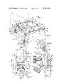
- FIG. 1is a perspective view of the retractor apparatus with the improved clamping device, the retractor apparatus being secured on the sterile side of the surgical drape to the side rail with the improved clamping device.
- FIG. 2is a cross-sectional view of the retractor apparatus in use, with a body being operated on, with the side rails and operating table, and longitudinal bars being shown in cross section.
- FIG. 3is a front view of the improved clamping device.
- FIG. 4is a side view of the improved clamping device with the surgical drape and side rail being shown in cross-section.
- FIG. 5is a cross-sectional view of the improved clamping device with parts shown whole for purposes of better clarity, taken along the line 5--5 in FIG. 3.
- FIG. 6is a cross-sectional view of the improved clamping device showing the bias spring with the lower member in phantom taken along the line 6--6 in FIG. 3.
- FIG. 7is a top view of the improved clamping device showing a cylindrical support member of the retractor apparatus in broken lines.
- the retractor apparatus with an improved clamping deviceis shown in connection with an operating table 10 of conventional construction. Rigidly secured to each side of the operating table is a side rail 12 the side rail 12 may be hinged as indicated at 14 where the bed is of a design to permit tilting of one portion of the table 10 with respect to the other.
- the side rail 12 as shown in FIG. 2is spaced outwardly from the bed, being secured thereto by posts 16.
- the frame 18, of the retractor apparatus, as shown in FIG. 1,preferably includes two inverted U-shaped support members 20 and 22. Each of the support members 20 and 22 actually consist of three separate members. Referring to the U-shaped member 20, the member includes two curved band members 24, and a removable center section 28.
- the U-shaped support 22, similarly,includes two curved band members 24 and a removable center section 28.
- the center sections 28are connected to the curved band members by connector members 29.
- Adjustably secured to the curved members 24are longitudinal rods 36 and 42, preferably of circular cross-section.
- the rod 36extends through apertures in clamps 38 and 40.
- the longitudinal rod 42extends through apertures in clamps 44 and 46.
- Clamps 38, 40, 44 and 46are movable along the curved members 24.
- retractors 48, 50 and 52are secured to the rods 36 and 42 by clamps 54, 56 and 58 respectively.
- a pusher 60is also adjustably attached to bar 36 by clamp 62. The retractors and pusher in combination, hold the portions of the body 11 along the edges of a surgical incision in a manner as to expose the area on which a surgeon must work. It should be understood, that the present invention is not limited to the above described retractor apparatus and includes other retractor apparatuses which are secured by support members to the side rails 12 of the operating table 10.
- An improved clamping device, generally indicated at 70secures a surgical drape 72 by clamping the surgical drape 72 against the side rail 12.
- the surgical drape 72is a conventional surgical drape having been sterilized and when placed on an operating table has a side 74 which is maintained sterilized and a side 76 which is not maintained sterilized, thus side 74 may be referred to as the sterilized side and side 76 as the unsterilized side.
- the surgical drape 72is placed over the body 11, which is unsterilized, to prevent infection in the area of the incision 64.
- the improved clamping device 70supports the retractor apparatus 18 by engaging the support members 24, and retains the support members in a fixed position with respect to the operating table 12.
- the improved clamping device 70is illustrated in more detail in FIGS. 3-6.
- the clamping device 70includes an upper member 78 with an upper clamping portion 80 for engagement with the side rail 12 over the surgical drape 72.
- a lower member 82 with a lower clamping portion 84is pivotally attached to the upper member 78 preferably by a pivot pin 86.
- the clamping portion 84 of the lower member 82similarly, engages the side rail 12 through surgical drape 72.
- the clamping portions 80 and 84preferably have substantially planer upper and lower surfaces 88 and 90, respectively. Beveled edges 92 and 94 define a gripping edge that grips the back corners 96 of the side rail 12.
- the lower member 82pivots to a clamping position about pivot pin 86 with first and second clamping portions gripping the corners 96 and holding the surgical drape 72 in place.
- the upper and lower clamping portions 80 and 84although shown gripping one thickness of surgical drape against a side rail having a rectangular cross-section, can grip a plurality of surgical drapes against various cross-sectional configurations of side rails.
- the clamping deviceis held in the clamping position around the side rail 12 by tightening mechanism 98.
- the tightening mechanism 98has a clamping knob 100 fixedly attached to a cylindrical threaded shaft 102 at one end which threadably engages a threaded passage 104, as shown in FIG. 5.
- the shaft 102has another end 106 which engages a lower outer surface of the upper member 78.
- the clamping deviceis placed in the clamping position by screwing the shaft 102 through the threaded passage 104.
- the end 106 of the shaft 102engages the lower outer surface of the upper member 78 when the shaft 102 is threaded through passage 104.
- the shaft 102when screwed through the passage 104 provides a force to pivot the lower member 82 about the pivot pin 86 with the lower clamping portion 84 moving toward the upper clamping portion 80.
- the clamping deviceis in the clamping position when the tightening mechanism 98 cannot be turned further by using reasonable force.
- the clamping knob 100is turned in an opposite direction withdrawing the end 106 from the lower surface of the upper member 78.
- a spring 108provides a biasing force to the upper member 78 and the lower member 82 biasing the clamping portions 80, 84 apart.
- the spring 108cooperates with the tightening mechanism 98 in moving the clamping portions 80 and 84 away from side rail 12 and surgical drape 72.
- the spring 108preferably sits in a depression 109 that is machined in the lower member 82.
- the spring 108has an upper member 110 preferably bent at a right angle and secured within an aperture 111, and a lower member contacting portion 112 which biases the upper member 78 and the lower member 82 in the direction indicated by arrow 114.
- a loop 116 of the spring 108surrounds the pivot pin 86 to hold the spring 108 in place. It should be understood that any type of biasing component is within the scope of the present invention.
- An upper passage 118preferably extends through the upper member 78 in a substantially vertical direction perpendicular to the longitudinal axis of the side rail 12.
- a lower passage 120extends through lower member 82 in a perpendicular direction with respect to the longitudinal axis of the side rail 12.
- the upper passage 118 and the lower passage 120are aligned with each other and accept a straight portion of the curved support member 24.
- the lower passage 120is larger than the upper passage 118 in a direction of the pivotal movement of the lower member 82.
- the larger diameter of the lower passage 120allows the lower member 82 to pivot into the clamping position and from the clamping position without interference of the curved support member 24.
- the diameter of the lower passage 120is sufficiently large that the upper passage 118 is aligned with at least some portion of the lower passage 120 sufficiently large to accept the curved support member 24.
- the upper passage 118has a first side 126 and second side 136 parallel to the side 126.
- the passage 118 having parallel sidesaccepts support members 24 of a substantially rectangular cross-section, as shown in FIG. 5.
- the passage 118preferably has semi-cylindrical portions 138 and 140 approximately in the center of and running along the entire length of the sides 126, 136, respectively. As shown in FIG. 7.
- the semi-cylindrical portions 138 and 140 in combination with the passage 118accept a cylindrical support member 24a.
- a tightening mechanism 124forces curved support member 24 against surface 126 of the upper passage 118, as best seen in FIGS. 5.
- the tightening mechanism 124 forcing cylindrical support member 24a against semi-cylindrical portion 138is best seen in FIG. 7.
- the tightening mechanism 124has a set screw 130 with a knob 128 of sufficient size to fit comfortably in a hand so that the set screw 130 can be turned with considerable force.
- the set screw 130threadably engages a threaded passage 132 in the upper chamber 78 and has a free end 134 projecting out of the passage 132 that engages the support member 24.
- the set screw 130frictionally holds the support member 24 against the surface 126 and retains the support member 24 in a fixed and secure position.
- the set screw 130is positioned in the upper member 78 to engage either the rectangular support member 24 or the cylindrical support member 24a.
- the surgical drapeIn use the surgical drape is placed over the patient with a lower end of the drape lying on the operating table.
- the surgical drapebeing sterilized, provides a sterile environment of the forthcoming operation on the patient.
- the clamping devicealso being sterile, is clamped at the appropriate position over the lower end of the surgical drape onto the side rail.
- the clamping deviceis clamped onto the side rail by turning the clamping knob 100 and forcing the end 106 of the shaft 102 against the surface of the upper member 78.
- the lower member 82will pivot to the clamping position.
- the support memberis then placed into the passages 118 and 120, and secured in the appropriate vertical position by turning the tightening mechanism 124 to force the upper member against side 126 of the upper passage.
- a clamping device for each support memberis similarly attached to the side rails of the operating table.
- the rest of the retractor apparatusas shown in FIG. 1, is then attached initially to the support members and the other elements of the retractor apparatus to complete the assembly of the apparatus.
- the entire retractor apparatusis easily adjusted along the horizontal length of the operating table by simply turning clamping knob 100 to unclamp the clamping device and move the device along the side rail.
- knob 128is turned in a direction that releases the support member.
- the support memberis then adjusted and clamping knob 128 is turned in the other direction to retain the retractor apparatus in a fixed position. Since the clamping device is on the sterile side of the surgical drape, both vertical and horizontal adjustments are easily made without endangering the sterile environment from contamination from underneath the surgical drape.
- the clamping device of the present inventionholds the surgical drape in place over the operating table.
Landscapes
- Health & Medical Sciences (AREA)
- Life Sciences & Earth Sciences (AREA)
- Surgery (AREA)
- Heart & Thoracic Surgery (AREA)
- Engineering & Computer Science (AREA)
- Biomedical Technology (AREA)
- Nuclear Medicine, Radiotherapy & Molecular Imaging (AREA)
- Medical Informatics (AREA)
- Molecular Biology (AREA)
- Animal Behavior & Ethology (AREA)
- General Health & Medical Sciences (AREA)
- Public Health (AREA)
- Veterinary Medicine (AREA)
- Surgical Instruments (AREA)
- Accommodation For Nursing Or Treatment Tables (AREA)
Abstract
Description
Claims (7)
Priority Applications (1)
| Application Number | Priority Date | Filing Date | Title |
|---|---|---|---|
| US06/245,378US4355631A (en) | 1981-03-19 | 1981-03-19 | Surgical retractor apparatus with improved clamping device |
Applications Claiming Priority (1)
| Application Number | Priority Date | Filing Date | Title |
|---|---|---|---|
| US06/245,378US4355631A (en) | 1981-03-19 | 1981-03-19 | Surgical retractor apparatus with improved clamping device |
Publications (1)
| Publication Number | Publication Date |
|---|---|
| US4355631Atrue US4355631A (en) | 1982-10-26 |
Family
ID=22926427
Family Applications (1)
| Application Number | Title | Priority Date | Filing Date |
|---|---|---|---|
| US06/245,378Expired - LifetimeUS4355631A (en) | 1981-03-19 | 1981-03-19 | Surgical retractor apparatus with improved clamping device |
Country Status (1)
| Country | Link |
|---|---|
| US (1) | US4355631A (en) |
Cited By (83)
| Publication number | Priority date | Publication date | Assignee | Title |
|---|---|---|---|---|
| US4616632A (en)* | 1985-01-31 | 1986-10-14 | Luis Wigoda | Lock for retractor apparatus |
| US4617916A (en)* | 1984-11-08 | 1986-10-21 | Minnesota Scientific, Inc. | Retractor apparatus |
| US4718151A (en)* | 1984-11-08 | 1988-01-12 | Minnesota Scientific, Inc. | Retractor apparatus |
| US4726356A (en)* | 1985-11-12 | 1988-02-23 | Kapp Surgical Instrument, Inc. | Cardiovascular and thoracic retractor |
| EP0261284A1 (en)* | 1986-09-23 | 1988-03-30 | Luis T. Wigoda | Retractor apparatus |
| US4747395A (en)* | 1983-08-24 | 1988-05-31 | Brief L Paul | Surgical retractor for bone surgery |
| EP0246086A3 (en)* | 1986-05-14 | 1988-08-10 | Aldo Sergio Kleiman | A procedure for carrying out a surgical operation and a retracting laparoscope for separating organs in surgery |
| US4805599A (en)* | 1987-06-25 | 1989-02-21 | Cedar Surgical, Inc. | Framework for supporting surgical instruments at a surgical wound |
| US4813401A (en)* | 1986-11-26 | 1989-03-21 | Grieshaber Manufacturing Company | Retractor |
| US4852552A (en)* | 1987-09-03 | 1989-08-01 | Pilling Co. | Sternal retractor |
| EP0336526A1 (en)* | 1988-02-25 | 1989-10-11 | Steven J. Phillips | Retractor apparatus for use in harvesting mammary arteries during heart by-pass surgery |
| US4949707A (en)* | 1984-11-08 | 1990-08-21 | Minnesota Scientific, Inc. | Retractor apparatus |
| US4971038A (en)* | 1989-04-26 | 1990-11-20 | Farley Daniel K | Table mounted surgical retractor |
| US4989587A (en)* | 1989-04-26 | 1991-02-05 | Farley Daniel K | Sternal retractor |
| WO1992020285A1 (en)* | 1991-05-24 | 1992-11-26 | Minnesota Scientific, Inc. | Surgical retractor apparatus with improved clamping device |
| USRE34150E (en)* | 1985-11-12 | 1992-12-29 | Kapp Surgical Instrument, Inc. | Cardiovascular and thoracic retractor |
| US5183033A (en)* | 1991-07-15 | 1993-02-02 | Wilk Peter J | Surgical instrument assembly and apparatus and surgical method |
| US5217463A (en)* | 1990-04-11 | 1993-06-08 | Mikhail W F Michael | Method for performing knee surgery and retractors for use therein |
| US5303694A (en)* | 1993-02-09 | 1994-04-19 | Mikhail Michael W E | Method for performing hip surgery and retractor for use therein |
| US5380331A (en)* | 1990-04-11 | 1995-01-10 | Mikhail; W. E. Michael | Method for performing knee surgery and retractors for use therein |
| US5538215A (en)* | 1994-11-15 | 1996-07-23 | Midmark Corporation | Siderail socket |
| US5704900A (en)* | 1995-10-20 | 1998-01-06 | Minnesota Scientific, Inc. | Method and apparatus for peritoneal distension |
| US5741210A (en)* | 1995-10-10 | 1998-04-21 | Minnesota Scientific, Inc. | Clamping device for a surgical retractor |
| US5769783A (en)* | 1996-06-27 | 1998-06-23 | Lone Star Medical Products, Inc. | Surgical retractor stay apparatus |
| US5792046A (en)* | 1996-02-22 | 1998-08-11 | Minnesota Scientific, Inc. | Cammed retractor clamp |
| US5876332A (en)* | 1997-07-24 | 1999-03-02 | Genzyme Corporation | Surgical support member |
| US5951467A (en)* | 1999-03-23 | 1999-09-14 | Applied Medical Technology, Inc. | Reconfigurable and self-retaining surgical retractor |
| US5957423A (en)* | 1997-11-05 | 1999-09-28 | Kronner; Richard F. | Low profile scope holder |
| US5964697A (en)* | 1996-04-22 | 1999-10-12 | Lone Star Medical Products, Inc. | Surgical retractor stay apparatus |
| US5964698A (en)* | 1999-01-20 | 1999-10-12 | Lone Star Medical Products, Inc. | Sliding hook assembly for use with a surgical retractor stay apparatus and methods for use |
| US5984867A (en)* | 1997-05-02 | 1999-11-16 | Heartport, Inc. | Surgical retractor and method of retracting |
| US6017304A (en)* | 1994-08-31 | 2000-01-25 | Vierra; Mark A. | Device and method for isolating a surgical site |
| US6042541A (en)* | 1995-10-10 | 2000-03-28 | Minnesota Scientific, Inc. | Clamping device for a surgical retractor |
| US6077221A (en)* | 1999-09-01 | 2000-06-20 | Lone Star Medical Products, Inc. | Surgical restraint system |
| US6117072A (en)* | 1998-12-28 | 2000-09-12 | Lone Star Medical Products, Inc. | Plastic stay assembly for use with MRI and X-ray imaging systems |
| US6190312B1 (en) | 1999-03-04 | 2001-02-20 | Lone Star Medical Products, Inc. | Variable geometry retractor and disposable retractor stay clips and method of use |
| WO2001019233A3 (en)* | 1999-09-14 | 2001-10-04 | Papillon Surgical | Breast bracket |
| US6331157B2 (en) | 1999-04-15 | 2001-12-18 | Heartport, Inc. | Apparatus and methods for off-pump cardiac surgery |
| EP1099436A3 (en)* | 1999-11-09 | 2002-10-16 | Rainer Urban | Operating table system |
| US6468207B1 (en) | 2000-02-04 | 2002-10-22 | Lone Star Medical Products, Inc. | Deep tissue surgical retractor apparatus and method of retracting tissue |
| US6499158B1 (en) | 2000-10-30 | 2002-12-31 | Steris, Inc. | Surgical table top and accessory clamp used thereon |
| US20030009081A1 (en)* | 1999-07-08 | 2003-01-09 | Chase Medical, Lp | Device and method for isolating a surface of a beating heart during surgery |
| US6598275B1 (en) | 2001-03-12 | 2003-07-29 | Steris, Inc. | Low shadow radiolucent surgical table, clamp systems, and accessories therefore |
| US6622980B2 (en)* | 2000-03-28 | 2003-09-23 | Hill-Rom Services, Inc. | Socket and rail clamp apparatus |
| US20030229273A1 (en)* | 2002-06-06 | 2003-12-11 | Mulac Anthony J. | Universal scissors joint apparatus |
| US20040073091A1 (en)* | 2002-08-23 | 2004-04-15 | Minnesota Scientific, Inc. | Stabilized table rail clamp |
| US20040186404A1 (en)* | 2003-03-17 | 2004-09-23 | Slater Robert R. | Stabilizer for forearm traction |
| US6939297B2 (en) | 1999-04-15 | 2005-09-06 | Heartport, Inc. | Apparatus and methods for cardiac surgery |
| US20050215866A1 (en)* | 2004-03-25 | 2005-09-29 | Depuy Spine, Inc. | Surgical retractor positioning device |
| US7020917B1 (en) | 2001-03-12 | 2006-04-04 | Steris Corporation | Radiolucent surgical table with low shadow accessory interface profile |
| US20060079864A1 (en)* | 2004-10-07 | 2006-04-13 | Kronner Richard F | Instrument support apparatus |
| US20060200005A1 (en)* | 2003-09-17 | 2006-09-07 | Levahn Intellectual Property Holding Company, Llc | Low profile, handle-in-between surgical scissors clamp |
| US20060255220A1 (en)* | 2004-11-10 | 2006-11-16 | Skripps Thomas K | Accessory rail clamp with latch and lock mechanisms |
| US20070158513A1 (en)* | 2006-01-12 | 2007-07-12 | Levahn Intellectual Property Holding Company, Llc | Surgical clamp and tool support system |
| US20070191686A1 (en)* | 2006-02-13 | 2007-08-16 | Levahn Intellectual Property Holding Company, Llc | Method of making a surgical clamp |
| US20080015639A1 (en)* | 2006-01-19 | 2008-01-17 | Bjork Todd M | Anchorless non-invasive force dissipation system for orthopedic instrumentation |
| US20080071145A1 (en)* | 2006-09-19 | 2008-03-20 | Levahn Intellectual Property Holding Company, Llc | Support Clamp For Retractor Bar Stock Of Generally Rectangular Cross-Section |
| US20080203644A1 (en)* | 2007-02-28 | 2008-08-28 | Dasilva Manuel F | Operating table support clamp |
| US20090226868A1 (en)* | 2006-05-19 | 2009-09-10 | Frassica James J | Anatomical model |
| US20090287062A1 (en)* | 2008-05-15 | 2009-11-19 | Farley Daniel K | Adjustable Rail Clamp |
| US20100108841A1 (en)* | 2008-10-31 | 2010-05-06 | Kronner Richard F | Base-clamp assembly |
| US20110119829A1 (en)* | 2007-08-24 | 2011-05-26 | ALLEN MEDICAL SYSTEMS ,INC. a corporation | Surgical table accessory platform |
| US20120065475A1 (en)* | 2002-11-19 | 2012-03-15 | J. Donald Hill | Methods, systems, and apparatus for performing minimally invasive coronary artery bypass graft surgery |
| US20120241571A1 (en)* | 2009-09-11 | 2012-09-27 | Thornhill Scientific Inc. | Connector system for medical device |
| US8485484B2 (en) | 2010-04-30 | 2013-07-16 | Richard F Kronner | Instrument assembly support apparatus |
| US20130253514A1 (en)* | 2006-09-15 | 2013-09-26 | Board Of Regents, The Univ. Of Tx System | System, Kit and Apparatus for Attachment of External Fixators for Bone Realignment |
| US20130269109A1 (en)* | 2007-02-02 | 2013-10-17 | Hansen Medical, Inc. | Mounting support assembly for suspending a medical instrument driver above an operating table |
| US8833707B2 (en) | 2010-07-15 | 2014-09-16 | Allen Medical Systems, Inc. | Disposable urology drainage bag |
| CN104873233A (en)* | 2015-05-15 | 2015-09-02 | 泰兴市中源医疗器械厂 | Pole clamping device for surgical incision expander |
| US9161875B2 (en) | 2012-09-07 | 2015-10-20 | Allen Medical Systems, Inc. | Multi-axis joint for a spar of a limb holder |
| EP2563235A4 (en)* | 2010-04-29 | 2016-07-06 | Automated Med Prod Corp | Telescoping surgical support and retractor system |
| WO2016118837A1 (en)* | 2015-01-22 | 2016-07-28 | Southern Research Institute | Surgical retraction frame, surgical retraction systems, and methods of using same |
| US20160296401A1 (en)* | 2014-01-22 | 2016-10-13 | Innovative Medical Products, Inc. | Strap clamp assembly |
| US20160324701A1 (en)* | 2014-01-13 | 2016-11-10 | Ferno-Washington, Inc. | Accessory clamp for emergency cots |
| US9498397B2 (en) | 2012-04-16 | 2016-11-22 | Allen Medical Systems, Inc. | Dual column surgical support system |
| US9655793B2 (en) | 2015-04-09 | 2017-05-23 | Allen Medical Systems, Inc. | Brake release mechanism for surgical table |
| US20170246059A1 (en)* | 2014-10-01 | 2017-08-31 | Ferno-Washington, Inc. | Modular stretcher or litter |
| US10064776B2 (en)* | 2014-02-17 | 2018-09-04 | Yingze Zhang | Orthopedic hospital bed and surgical table with the functions of traction and reduction |
| US11202731B2 (en) | 2018-02-28 | 2021-12-21 | Allen Medical Systems, Inc. | Surgical patient support and methods thereof |
| US11213448B2 (en) | 2017-07-31 | 2022-01-04 | Allen Medical Systems, Inc. | Rotation lockout for surgical support |
| US20230091158A1 (en)* | 2006-09-15 | 2023-03-23 | Board Of Regents, The University Of Texas System | System, Kit and Apparatus for Attachment of External Fixators for Bone Realignment |
| US11707294B2 (en)* | 2018-02-15 | 2023-07-25 | Minnetronix Neuro, Inc. | Medical device for accessing the central nervous system |
| US11957628B2 (en) | 2014-01-22 | 2024-04-16 | Innovative Medical Products, Inc. | Strap clamp assembly |
Citations (9)
| Publication number | Priority date | Publication date | Assignee | Title |
|---|---|---|---|---|
| DE460145C (en)* | 1927-04-28 | 1928-05-22 | Ernst Koltai Dr | Device for setting and holding a speculum |
| US1747799A (en)* | 1928-09-14 | 1930-02-18 | Sharp & Smith | Retractor |
| US2586488A (en)* | 1949-05-11 | 1952-02-19 | David P Smith | Table supported surgical retractor |
| FR1235135A (en)* | 1959-09-14 | 1960-10-26 | Articulated mechanical support, more specifically designed for the correct maintenance of retractors used in surgery | |
| US3221743A (en)* | 1962-08-13 | 1965-12-07 | Pa Co Inc Du | System and apparatus for positioning and securing surgical implements |
| US3572326A (en)* | 1968-05-06 | 1971-03-23 | Medic Made Inc | Chest wall retractor |
| US3823709A (en)* | 1973-04-27 | 1974-07-16 | Guire G Mc | Table supported surgical retractor and pelvic support |
| US3910538A (en)* | 1973-05-04 | 1975-10-07 | Carlo Baitella | Jointed stand for dial gages |
| US4254763A (en)* | 1979-06-07 | 1981-03-10 | Codman & Shurtleff, Inc. | Surgical retractor assembly |
- 1981
- 1981-03-19USUS06/245,378patent/US4355631A/ennot_activeExpired - Lifetime
Patent Citations (9)
| Publication number | Priority date | Publication date | Assignee | Title |
|---|---|---|---|---|
| DE460145C (en)* | 1927-04-28 | 1928-05-22 | Ernst Koltai Dr | Device for setting and holding a speculum |
| US1747799A (en)* | 1928-09-14 | 1930-02-18 | Sharp & Smith | Retractor |
| US2586488A (en)* | 1949-05-11 | 1952-02-19 | David P Smith | Table supported surgical retractor |
| FR1235135A (en)* | 1959-09-14 | 1960-10-26 | Articulated mechanical support, more specifically designed for the correct maintenance of retractors used in surgery | |
| US3221743A (en)* | 1962-08-13 | 1965-12-07 | Pa Co Inc Du | System and apparatus for positioning and securing surgical implements |
| US3572326A (en)* | 1968-05-06 | 1971-03-23 | Medic Made Inc | Chest wall retractor |
| US3823709A (en)* | 1973-04-27 | 1974-07-16 | Guire G Mc | Table supported surgical retractor and pelvic support |
| US3910538A (en)* | 1973-05-04 | 1975-10-07 | Carlo Baitella | Jointed stand for dial gages |
| US4254763A (en)* | 1979-06-07 | 1981-03-10 | Codman & Shurtleff, Inc. | Surgical retractor assembly |
Non-Patent Citations (2)
| Title |
|---|
| Codman & Shurtleff, Price List of Great Eastern Lumber Company, Inc.* |
| Poly-Tract Retractor System of Minnesota Scientific Inc., Thompson Retractor by Richard C. Thompson, M.D.* |
Cited By (136)
| Publication number | Priority date | Publication date | Assignee | Title |
|---|---|---|---|---|
| US4747395A (en)* | 1983-08-24 | 1988-05-31 | Brief L Paul | Surgical retractor for bone surgery |
| US4949707A (en)* | 1984-11-08 | 1990-08-21 | Minnesota Scientific, Inc. | Retractor apparatus |
| US4617916A (en)* | 1984-11-08 | 1986-10-21 | Minnesota Scientific, Inc. | Retractor apparatus |
| US4718151A (en)* | 1984-11-08 | 1988-01-12 | Minnesota Scientific, Inc. | Retractor apparatus |
| US4616632A (en)* | 1985-01-31 | 1986-10-14 | Luis Wigoda | Lock for retractor apparatus |
| US4726356A (en)* | 1985-11-12 | 1988-02-23 | Kapp Surgical Instrument, Inc. | Cardiovascular and thoracic retractor |
| USRE34150E (en)* | 1985-11-12 | 1992-12-29 | Kapp Surgical Instrument, Inc. | Cardiovascular and thoracic retractor |
| EP0246086A3 (en)* | 1986-05-14 | 1988-08-10 | Aldo Sergio Kleiman | A procedure for carrying out a surgical operation and a retracting laparoscope for separating organs in surgery |
| EP0261284A1 (en)* | 1986-09-23 | 1988-03-30 | Luis T. Wigoda | Retractor apparatus |
| US4813401A (en)* | 1986-11-26 | 1989-03-21 | Grieshaber Manufacturing Company | Retractor |
| US4805599A (en)* | 1987-06-25 | 1989-02-21 | Cedar Surgical, Inc. | Framework for supporting surgical instruments at a surgical wound |
| US4852552A (en)* | 1987-09-03 | 1989-08-01 | Pilling Co. | Sternal retractor |
| EP0336526A1 (en)* | 1988-02-25 | 1989-10-11 | Steven J. Phillips | Retractor apparatus for use in harvesting mammary arteries during heart by-pass surgery |
| US4971038A (en)* | 1989-04-26 | 1990-11-20 | Farley Daniel K | Table mounted surgical retractor |
| US4989587A (en)* | 1989-04-26 | 1991-02-05 | Farley Daniel K | Sternal retractor |
| US5290290A (en)* | 1990-04-11 | 1994-03-01 | Mikhail Michael W E | Method for performing knee surgery and retractors for use therein |
| US5308350A (en)* | 1990-04-11 | 1994-05-03 | Mikhail Michael W E | Femoral distractor for use in knee surgery |
| US5217463A (en)* | 1990-04-11 | 1993-06-08 | Mikhail W F Michael | Method for performing knee surgery and retractors for use therein |
| US5397330A (en)* | 1990-04-11 | 1995-03-14 | Mikhail; E. Michael | Posterior cruciate ligament retractor for use in performing knee surgery |
| US5380331A (en)* | 1990-04-11 | 1995-01-10 | Mikhail; W. E. Michael | Method for performing knee surgery and retractors for use therein |
| US5308349A (en)* | 1990-04-11 | 1994-05-03 | Mikhail W F Michael | Method for performing knee surgery and retractors for use therein |
| US5400772A (en)* | 1991-05-24 | 1995-03-28 | Minnesota Scientific, Inc. | Surgical retractor apparatus with improved clamping device |
| WO1992020285A1 (en)* | 1991-05-24 | 1992-11-26 | Minnesota Scientific, Inc. | Surgical retractor apparatus with improved clamping device |
| US5318012A (en)* | 1991-07-15 | 1994-06-07 | Wilk Peter J | Method for lifting abdominal wall during laparoscopic surgery |
| US5353785A (en)* | 1991-07-15 | 1994-10-11 | Wilk Peter J | Method for lifting abdominal wall during laparoscopic surgery |
| US5183033A (en)* | 1991-07-15 | 1993-02-02 | Wilk Peter J | Surgical instrument assembly and apparatus and surgical method |
| US5303694A (en)* | 1993-02-09 | 1994-04-19 | Mikhail Michael W E | Method for performing hip surgery and retractor for use therein |
| US20040254425A1 (en)* | 1994-08-31 | 2004-12-16 | Vierra Mark A. | Device and method for isolating a surgical site |
| US6821247B2 (en) | 1994-08-31 | 2004-11-23 | Heartport, Inc. | Device and method for isolating a surgical site |
| US6017304A (en)* | 1994-08-31 | 2000-01-25 | Vierra; Mark A. | Device and method for isolating a surgical site |
| US7025722B2 (en) | 1994-08-31 | 2006-04-11 | Heartport, Inc. | Device and method for isolating a surgical site |
| US6482151B1 (en) | 1994-08-31 | 2002-11-19 | Heartport, Inc. | Method of performing a procedure on a coronary artery |
| US6149583A (en)* | 1994-08-31 | 2000-11-21 | Heartport, Inc. | Device and method for isolating a surgical site |
| US6139492A (en)* | 1994-08-31 | 2000-10-31 | Heartport, Inc. | Device and method for isolating a surgical site |
| US5538215A (en)* | 1994-11-15 | 1996-07-23 | Midmark Corporation | Siderail socket |
| US5741210A (en)* | 1995-10-10 | 1998-04-21 | Minnesota Scientific, Inc. | Clamping device for a surgical retractor |
| US6042541A (en)* | 1995-10-10 | 2000-03-28 | Minnesota Scientific, Inc. | Clamping device for a surgical retractor |
| US5704900A (en)* | 1995-10-20 | 1998-01-06 | Minnesota Scientific, Inc. | Method and apparatus for peritoneal distension |
| US5792046A (en)* | 1996-02-22 | 1998-08-11 | Minnesota Scientific, Inc. | Cammed retractor clamp |
| US5964697A (en)* | 1996-04-22 | 1999-10-12 | Lone Star Medical Products, Inc. | Surgical retractor stay apparatus |
| US5769783A (en)* | 1996-06-27 | 1998-06-23 | Lone Star Medical Products, Inc. | Surgical retractor stay apparatus |
| US6416468B2 (en) | 1997-05-02 | 2002-07-09 | Heartport, Inc. | Method of retracting a portion of a patient's body |
| US5984867A (en)* | 1997-05-02 | 1999-11-16 | Heartport, Inc. | Surgical retractor and method of retracting |
| US5876332A (en)* | 1997-07-24 | 1999-03-02 | Genzyme Corporation | Surgical support member |
| US5957423A (en)* | 1997-11-05 | 1999-09-28 | Kronner; Richard F. | Low profile scope holder |
| US6117072A (en)* | 1998-12-28 | 2000-09-12 | Lone Star Medical Products, Inc. | Plastic stay assembly for use with MRI and X-ray imaging systems |
| US5964698A (en)* | 1999-01-20 | 1999-10-12 | Lone Star Medical Products, Inc. | Sliding hook assembly for use with a surgical retractor stay apparatus and methods for use |
| US6190312B1 (en) | 1999-03-04 | 2001-02-20 | Lone Star Medical Products, Inc. | Variable geometry retractor and disposable retractor stay clips and method of use |
| US5951467A (en)* | 1999-03-23 | 1999-09-14 | Applied Medical Technology, Inc. | Reconfigurable and self-retaining surgical retractor |
| US20020016527A1 (en)* | 1999-04-15 | 2002-02-07 | Hancock Andrew H. | Apparatus and methods for off-pump cardiac surgery |
| US6331157B2 (en) | 1999-04-15 | 2001-12-18 | Heartport, Inc. | Apparatus and methods for off-pump cardiac surgery |
| US6939297B2 (en) | 1999-04-15 | 2005-09-06 | Heartport, Inc. | Apparatus and methods for cardiac surgery |
| US6740029B2 (en) | 1999-07-08 | 2004-05-25 | Chase Medical, L.P. | Device and method for isolating a surface of a beating heart during surgery |
| US20030009081A1 (en)* | 1999-07-08 | 2003-01-09 | Chase Medical, Lp | Device and method for isolating a surface of a beating heart during surgery |
| US6077221A (en)* | 1999-09-01 | 2000-06-20 | Lone Star Medical Products, Inc. | Surgical restraint system |
| US6589254B2 (en) | 1999-09-14 | 2003-07-08 | Mark G. Fontenot | Breast bracket |
| WO2001019233A3 (en)* | 1999-09-14 | 2001-10-04 | Papillon Surgical | Breast bracket |
| EP1099436A3 (en)* | 1999-11-09 | 2002-10-16 | Rainer Urban | Operating table system |
| US6468207B1 (en) | 2000-02-04 | 2002-10-22 | Lone Star Medical Products, Inc. | Deep tissue surgical retractor apparatus and method of retracting tissue |
| US6622980B2 (en)* | 2000-03-28 | 2003-09-23 | Hill-Rom Services, Inc. | Socket and rail clamp apparatus |
| US7159832B2 (en) | 2000-10-30 | 2007-01-09 | Steris Inc. | Surgical table top and accessory clamp used thereon |
| US6671904B2 (en) | 2000-10-30 | 2004-01-06 | Steris, Inc. | Surgical table top and accessory clamp used thereon |
| US6499158B1 (en) | 2000-10-30 | 2002-12-31 | Steris, Inc. | Surgical table top and accessory clamp used thereon |
| US7020917B1 (en) | 2001-03-12 | 2006-04-04 | Steris Corporation | Radiolucent surgical table with low shadow accessory interface profile |
| US6912959B2 (en) | 2001-03-12 | 2005-07-05 | Steris Inc. | Surgical table and clamp system |
| US6598275B1 (en) | 2001-03-12 | 2003-07-29 | Steris, Inc. | Low shadow radiolucent surgical table, clamp systems, and accessories therefore |
| US20030229273A1 (en)* | 2002-06-06 | 2003-12-11 | Mulac Anthony J. | Universal scissors joint apparatus |
| US7156806B2 (en)* | 2002-08-23 | 2007-01-02 | Minnesota Scientific, Inc. | Stabilized table rail clamp |
| US20040073091A1 (en)* | 2002-08-23 | 2004-04-15 | Minnesota Scientific, Inc. | Stabilized table rail clamp |
| WO2004034871A3 (en)* | 2002-08-23 | 2004-08-19 | Minnesota Scientific Inc | Stabilized table (12) rail (14) clamp |
| US20120065475A1 (en)* | 2002-11-19 | 2012-03-15 | J. Donald Hill | Methods, systems, and apparatus for performing minimally invasive coronary artery bypass graft surgery |
| US8828033B2 (en)* | 2002-11-19 | 2014-09-09 | J. Donald Hill | Methods, systems, and apparatus for performing minimally invasive coronary artery bypass graft surgery |
| US7143458B2 (en)* | 2003-03-17 | 2006-12-05 | Slater Jr Robert R | Stabilizer for forearm traction |
| US20040186404A1 (en)* | 2003-03-17 | 2004-09-23 | Slater Robert R. | Stabilizer for forearm traction |
| US20060200005A1 (en)* | 2003-09-17 | 2006-09-07 | Levahn Intellectual Property Holding Company, Llc | Low profile, handle-in-between surgical scissors clamp |
| US20050215866A1 (en)* | 2004-03-25 | 2005-09-29 | Depuy Spine, Inc. | Surgical retractor positioning device |
| US7435219B2 (en) | 2004-03-25 | 2008-10-14 | Depuy Spine, Inc. | Surgical retractor positioning device |
| US20090018401A1 (en)* | 2004-03-25 | 2009-01-15 | Depuy Spine, Inc. | Surgical retractor positioning device |
| US7670281B2 (en) | 2004-10-07 | 2010-03-02 | Kronner Richard F | Instrument support apparatus |
| US8480561B2 (en) | 2004-10-07 | 2013-07-09 | Richard F. Kronner | Instrument support apparatus |
| US20100114117A1 (en)* | 2004-10-07 | 2010-05-06 | Kronner Richard F | Instrument support apparatus |
| US20060079864A1 (en)* | 2004-10-07 | 2006-04-13 | Kronner Richard F | Instrument support apparatus |
| US20060255220A1 (en)* | 2004-11-10 | 2006-11-16 | Skripps Thomas K | Accessory rail clamp with latch and lock mechanisms |
| US7520007B2 (en) | 2004-11-10 | 2009-04-21 | Allen Medical Systems, Inc. | Accessory rail clamp with latch and lock mechanisms |
| US20070158513A1 (en)* | 2006-01-12 | 2007-07-12 | Levahn Intellectual Property Holding Company, Llc | Surgical clamp and tool support system |
| US20080015639A1 (en)* | 2006-01-19 | 2008-01-17 | Bjork Todd M | Anchorless non-invasive force dissipation system for orthopedic instrumentation |
| US20070191686A1 (en)* | 2006-02-13 | 2007-08-16 | Levahn Intellectual Property Holding Company, Llc | Method of making a surgical clamp |
| US20090226868A1 (en)* | 2006-05-19 | 2009-09-10 | Frassica James J | Anatomical model |
| US8403676B2 (en)* | 2006-05-19 | 2013-03-26 | Olympus Endo Technology America Inc. | Anatomical model |
| US20230091158A1 (en)* | 2006-09-15 | 2023-03-23 | Board Of Regents, The University Of Texas System | System, Kit and Apparatus for Attachment of External Fixators for Bone Realignment |
| US10433872B2 (en)* | 2006-09-15 | 2019-10-08 | Board Of Regents, The University Of Texas System | System, kit and apparatus for attachment of external fixators for bone realignment |
| US11684391B2 (en) | 2006-09-15 | 2023-06-27 | Board Of Regents, The University Of Texas System | System, kit and apparatus for attachment of external fixators for bone realignment |
| US20130253514A1 (en)* | 2006-09-15 | 2013-09-26 | Board Of Regents, The Univ. Of Tx System | System, Kit and Apparatus for Attachment of External Fixators for Bone Realignment |
| US20080071145A1 (en)* | 2006-09-19 | 2008-03-20 | Levahn Intellectual Property Holding Company, Llc | Support Clamp For Retractor Bar Stock Of Generally Rectangular Cross-Section |
| US20130269109A1 (en)* | 2007-02-02 | 2013-10-17 | Hansen Medical, Inc. | Mounting support assembly for suspending a medical instrument driver above an operating table |
| US9566201B2 (en)* | 2007-02-02 | 2017-02-14 | Hansen Medical, Inc. | Mounting support assembly for suspending a medical instrument driver above an operating table |
| US7686267B2 (en) | 2007-02-28 | 2010-03-30 | Dasilva Manuel F | Operating table support clamp |
| US20080203644A1 (en)* | 2007-02-28 | 2008-08-28 | Dasilva Manuel F | Operating table support clamp |
| US8397323B2 (en) | 2007-08-24 | 2013-03-19 | Allen Medical Systems, Inc. | Surgical table accessory platform |
| US20110119829A1 (en)* | 2007-08-24 | 2011-05-26 | ALLEN MEDICAL SYSTEMS ,INC. a corporation | Surgical table accessory platform |
| US20090287062A1 (en)* | 2008-05-15 | 2009-11-19 | Farley Daniel K | Adjustable Rail Clamp |
| US20120136215A1 (en)* | 2008-05-15 | 2012-05-31 | Farley Daniel K | Adjustable Rail Clamp with Clamp Locking Device |
| US8100827B2 (en) | 2008-05-15 | 2012-01-24 | Thompson Surgical Instruments, Inc. | Adjustable rail clamp |
| US8617064B2 (en)* | 2008-05-15 | 2013-12-31 | Thompson Surgical Instruments, Inc. | Adjustable rail clamp with clamp locking device |
| US20100108841A1 (en)* | 2008-10-31 | 2010-05-06 | Kronner Richard F | Base-clamp assembly |
| US8313070B2 (en) | 2008-10-31 | 2012-11-20 | Kronner Richard F | Base-clamp assembly |
| US20120241571A1 (en)* | 2009-09-11 | 2012-09-27 | Thornhill Scientific Inc. | Connector system for medical device |
| EP2563235A4 (en)* | 2010-04-29 | 2016-07-06 | Automated Med Prod Corp | Telescoping surgical support and retractor system |
| US8485484B2 (en) | 2010-04-30 | 2013-07-16 | Richard F Kronner | Instrument assembly support apparatus |
| US8833707B2 (en) | 2010-07-15 | 2014-09-16 | Allen Medical Systems, Inc. | Disposable urology drainage bag |
| US10993864B2 (en) | 2012-04-16 | 2021-05-04 | Allen Medical Systems, Inc. | Bracket attachment apparatus for dual column surgical table |
| US12186242B2 (en) | 2012-04-16 | 2025-01-07 | Allen Medical Systems, Inc. | Dual column surgical table having a single-handle unlock for table rotation |
| US11938065B2 (en) | 2012-04-16 | 2024-03-26 | Allen Medical Systems, Inc. | Table top to bracket coupling apparatus for spine surgery table |
| US9968503B2 (en) | 2012-04-16 | 2018-05-15 | Allen Medical Systems, Inc. | Dual column surgical table having a single-handle unlock for table rotation |
| US11452657B2 (en) | 2012-04-16 | 2022-09-27 | Allen Medical Systems, Inc. | Dual column surgical table having a single-handle unlock for table rotation |
| US9498397B2 (en) | 2012-04-16 | 2016-11-22 | Allen Medical Systems, Inc. | Dual column surgical support system |
| US9161875B2 (en) | 2012-09-07 | 2015-10-20 | Allen Medical Systems, Inc. | Multi-axis joint for a spar of a limb holder |
| US10238568B2 (en) | 2012-09-07 | 2019-03-26 | Allen Medical Systems, Inc. | Release handle mechanisms for a spar of a limb holder |
| US10398615B2 (en) | 2012-09-07 | 2019-09-03 | Allen Medical Systems, Inc. | Multi-axis joint for a spar of a limb holder |
| US20160324701A1 (en)* | 2014-01-13 | 2016-11-10 | Ferno-Washington, Inc. | Accessory clamp for emergency cots |
| US20160296401A1 (en)* | 2014-01-22 | 2016-10-13 | Innovative Medical Products, Inc. | Strap clamp assembly |
| US11957628B2 (en) | 2014-01-22 | 2024-04-16 | Innovative Medical Products, Inc. | Strap clamp assembly |
| US10064776B2 (en)* | 2014-02-17 | 2018-09-04 | Yingze Zhang | Orthopedic hospital bed and surgical table with the functions of traction and reduction |
| US11213439B2 (en)* | 2014-10-01 | 2022-01-04 | Ferno-Washington, Inc. | Modular stretcher or litter |
| US20170246059A1 (en)* | 2014-10-01 | 2017-08-31 | Ferno-Washington, Inc. | Modular stretcher or litter |
| WO2016118837A1 (en)* | 2015-01-22 | 2016-07-28 | Southern Research Institute | Surgical retraction frame, surgical retraction systems, and methods of using same |
| US9655793B2 (en) | 2015-04-09 | 2017-05-23 | Allen Medical Systems, Inc. | Brake release mechanism for surgical table |
| CN104873233A (en)* | 2015-05-15 | 2015-09-02 | 泰兴市中源医疗器械厂 | Pole clamping device for surgical incision expander |
| US11752055B2 (en) | 2017-07-31 | 2023-09-12 | Allen Medical Systems, Inc. | Rotation lockout for surgical support |
| US11554068B2 (en) | 2017-07-31 | 2023-01-17 | Allen Medical Systems, Inc. | Rotation lockout for surgical support |
| US11213448B2 (en) | 2017-07-31 | 2022-01-04 | Allen Medical Systems, Inc. | Rotation lockout for surgical support |
| US12029689B2 (en) | 2017-07-31 | 2024-07-09 | Allen Medical Systems, Inc. | Controls for surgical support apparatus |
| US11707294B2 (en)* | 2018-02-15 | 2023-07-25 | Minnetronix Neuro, Inc. | Medical device for accessing the central nervous system |
| US12232765B2 (en) | 2018-02-15 | 2025-02-25 | Minnetronix Neuro, Inc. | Medical device for accessing the central nervous system |
| US11202731B2 (en) | 2018-02-28 | 2021-12-21 | Allen Medical Systems, Inc. | Surgical patient support and methods thereof |
| US12220359B2 (en) | 2018-02-28 | 2025-02-11 | Allen Medical Systems, Inc. | Surgical patient support and methods thereof |
Similar Documents
| Publication | Publication Date | Title |
|---|---|---|
| US4355631A (en) | Surgical retractor apparatus with improved clamping device | |
| US5400772A (en) | Surgical retractor apparatus with improved clamping device | |
| US4971037A (en) | Surgical retractor support | |
| US5741210A (en) | Clamping device for a surgical retractor | |
| CA1289030C (en) | Framework for supporting surgical instruments at a surgical wound | |
| US5231974A (en) | Self retaining retractor | |
| US6671904B2 (en) | Surgical table top and accessory clamp used thereon | |
| US4913413A (en) | Universal leg holder | |
| US4971038A (en) | Table mounted surgical retractor | |
| US3572326A (en) | Chest wall retractor | |
| US4457300A (en) | Surgical retractor | |
| US4989587A (en) | Sternal retractor | |
| US4108426A (en) | Device for holding the head of a patient | |
| US3221743A (en) | System and apparatus for positioning and securing surgical implements | |
| US4549540A (en) | Thigh restraining apparatus and method | |
| US6023800A (en) | Removable accessory for a surgical table | |
| US5009407A (en) | Surgical table for microscopic lumbar laminectomy surgery | |
| US4624245A (en) | Hip displacement apparatus | |
| US3844550A (en) | Pelvic support for surgical operations | |
| US4373709A (en) | Surgical limb holder | |
| US4390011A (en) | Adjustable surgical arm rest and instrument platform | |
| US4510926A (en) | Support device for medical instruments | |
| US3774773A (en) | Magnetic medical tool holder stand | |
| US20030229273A1 (en) | Universal scissors joint apparatus | |
| DE69331285T2 (en) | SURGICAL APPARATUS FOR ACQUISITION OF THE HAND |
Legal Events
| Date | Code | Title | Description |
|---|---|---|---|
| AS | Assignment | Owner name:MINNESOTA SCIENTIFIC,INC. 2520 KENNEDY ST.N.E. MPL Free format text:ASSIGNMENT OF ASSIGNORS INTEREST.;ASSIGNOR:LE VAHN BRUCE A.;REEL/FRAME:003873/0403 Effective date:19810317 | |
| STCF | Information on status: patent grant | Free format text:PATENTED CASE | |
| FEPP | Fee payment procedure | Free format text:MAINTENANCE FEE REMINDER MAILED (ORIGINAL EVENT CODE: REM.); ENTITY STATUS OF PATENT OWNER: SMALL ENTITY | |
| FEPP | Fee payment procedure | Free format text:SURCHARGE FOR LATE PAYMENT, PL 96-517 (ORIGINAL EVENT CODE: M176); ENTITY STATUS OF PATENT OWNER: SMALL ENTITY | |
| MAFP | Maintenance fee payment | Free format text:PAYMENT OF MAINTENANCE FEE, 4TH YEAR, PL 96-517 (ORIGINAL EVENT CODE: M170); ENTITY STATUS OF PATENT OWNER: SMALL ENTITY Year of fee payment:4 | |
| FEPP | Fee payment procedure | Free format text:PAYOR NUMBER ASSIGNED (ORIGINAL EVENT CODE: ASPN); ENTITY STATUS OF PATENT OWNER: SMALL ENTITY | |
| MAFP | Maintenance fee payment | Free format text:PAYMENT OF MAINTENANCE FEE, 8TH YEAR, PL 96-517 (ORIGINAL EVENT CODE: M171); ENTITY STATUS OF PATENT OWNER: SMALL ENTITY Year of fee payment:8 | |
| MAFP | Maintenance fee payment | Free format text:PAYMENT OF MAINTENANCE FEE, 12TH YEAR, LARGE ENTITY (ORIGINAL EVENT CODE: M185); ENTITY STATUS OF PATENT OWNER: SMALL ENTITY Year of fee payment:12 | |
| FEPP | Fee payment procedure | Free format text:PAT HOLDER CLAIMS SMALL ENTITY STATUS - SMALL BUSINESS (ORIGINAL EVENT CODE: SM02); ENTITY STATUS OF PATENT OWNER: SMALL ENTITY | |
| REFU | Refund | Free format text:REFUND OF EXCESS PAYMENTS PROCESSED (ORIGINAL EVENT CODE: R169); ENTITY STATUS OF PATENT OWNER: SMALL ENTITY |