US4352565A - Speckle pattern interferometer - Google Patents
Speckle pattern interferometerDownload PDFInfo
- Publication number
- US4352565A US4352565AUS06/224,184US22418481AUS4352565AUS 4352565 AUS4352565 AUS 4352565AUS 22418481 AUS22418481 AUS 22418481AUS 4352565 AUS4352565 AUS 4352565A
- Authority
- US
- United States
- Prior art keywords
- interferometer
- fiber
- beams
- optical fiber
- optical
- Prior art date
- Legal status (The legal status is an assumption and is not a legal conclusion. Google has not performed a legal analysis and makes no representation as to the accuracy of the status listed.)
- Expired - Fee Related
Links
- 239000013307optical fiberSubstances0.000claimsabstractdescription20
- 230000003287optical effectEffects0.000claimsabstractdescription17
- 239000000835fiberSubstances0.000claimsdescription7
- 238000005253claddingMethods0.000claimsdescription4
- 239000000463materialSubstances0.000claimsdescription4
- 230000001427coherent effectEffects0.000claimsdescription2
- 230000002745absorbentEffects0.000claims1
- 239000002250absorbentSubstances0.000claims1
- 230000005465channelingEffects0.000claims1
- 238000009659non-destructive testingMethods0.000abstractdescription3
- 238000011835investigationMethods0.000abstract1
- 238000006073displacement reactionMethods0.000description3
- PPBRXRYQALVLMV-UHFFFAOYSA-NStyreneChemical compoundC=CC1=CC=CC=C1PPBRXRYQALVLMV-UHFFFAOYSA-N0.000description2
- 230000007547defectEffects0.000description2
- 230000001788irregularEffects0.000description2
- 238000000034methodMethods0.000description2
- 239000004593EpoxySubstances0.000description1
- XAGFODPZIPBFFR-UHFFFAOYSA-NaluminiumChemical compound[Al]XAGFODPZIPBFFR-UHFFFAOYSA-N0.000description1
- 229910052782aluminiumInorganic materials0.000description1
- 201000009310astigmatismDiseases0.000description1
- 238000005266castingMethods0.000description1
- 239000011248coating agentSubstances0.000description1
- 238000000576coating methodMethods0.000description1
- 230000000694effectsEffects0.000description1
- 239000011521glassSubstances0.000description1
- 230000002452interceptive effectEffects0.000description1
- 238000005305interferometryMethods0.000description1
Images

Classifications
- G—PHYSICS
- G01—MEASURING; TESTING
- G01B—MEASURING LENGTH, THICKNESS OR SIMILAR LINEAR DIMENSIONS; MEASURING ANGLES; MEASURING AREAS; MEASURING IRREGULARITIES OF SURFACES OR CONTOURS
- G01B9/00—Measuring instruments characterised by the use of optical techniques
- G01B9/02—Interferometers
- G01B9/02094—Speckle interferometers, i.e. for detecting changes in speckle pattern
Definitions
- This inventionrelates to a laser beam speckle pattern interferometer, and more particularly to such a device for use in the nondestructive testing of the structural characteristics of certain objects.
- Speckle pattern interferometryis utilized in the prior art for the nondestructive testing of the structural characteristics of objects such as panels, turbine blades, bonding joints in panels, etc.
- a typical such prior art speckle pattern interferometeris described in U.S. Pat. No. 4,018,531, issued Apr. 19, 1977.
- a laser beamis employed, this beam being split by means of a beam splitter into reference and object beams.
- the object beamis directed against the surface of an object to be tested from where it is reflected through an appropriate optical system to a sensor surface of a suitable detector such as a vidicon.
- the reference beamis directed by optical means to this same sensing surface for combining with the object beam.
- the object and reference beamsboth come from the same direction and have the same path length so that when they are combined, an interference pattern is produced in accordance with any displacement from a given position that the surface of the object may undergo.
- the objectis generally vibrated cyclically at a given frequency which may be in the low audio range, this resulting in an irregular displacement of any portions of the object surface having structural breaks or defects therein.
- the interfering signals received by the detectorare fed to an appropriate electronic processor and from there to a display screen whereon a speckle pattern is produced in which any defects in the object are indicated.
- the object and reference beamsare generally recombined with each other, either by means of an optical wedge or an optical system employing a group of mirrors (as in the aforementioned Pat. No. 4,018,531). It has been found that both wedge and mirror techniques for recombining the beams present significant problems in maintaining alignment, particularly in field uses where the equipment may be subject to vibration, jarring, and other mechanical disturbances. Wedge type systems generally suffer from astigmatism which somewhat impairs the quality of the image produced on the display screen and generally requires the use of focusing lenses having relatively long focal lengths, due to the fact that the wedge must be placed between the lens and the detector.
- the interferometer of the present inventionovercomes the shortcomings of the prior art enumerated above by employing an optical fiber for conveying the reference beam to the detector, thus obviating the need for an optical wedge or a mirror system to combine the object and reference beams.
- the interferometer of my inventionis as follows: A laser beam is split into object and reference beams by a conventional beam splitter. The object beam is focused onto the surface of an object to be tested, this object being vibratorily driven. The reference beam is directed through a lens onto the end of an optical fiber which conducts this beam to a position directly opposite a detector surface which may be the screen of a vidicon. The object beam is reflected from the surface of the object being tested directly toward the surface of this same detector where it is combined with the reference beam. Undesired modes of light are stripped from the optical fiber by means of a "mode stripper" device which effectively dissipates such undesired optical modes which may be developed in the cladding of the optical fiber. The output of the vidicon detector is fed to an electronic processor where the signals are processed to generate a speckle pattern display on a video monitor screen.
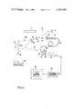
- FIG. 1is a schematic drawing illustrating a preferred embodiment of the invention.
- FIG. 2is an elevational drawing in cross section illustrating a mode stripper which may be employed in the system of the invention.
- a coherent light beam 12is generated by laser 11, this light beam being reflected from the surface of mirror 14 to the surface of beam splitter 16.
- Beam splitter 16splits the beam into a reference beam 17 and an object beam 18.
- Object beam 18is expanded and projected onto the surface 20a of an object 20 to be tested by means of lens 21.
- the expanded object light beam 18ais reflected off the surface 20a along an optical axis indicated by arrow 24, this light beam passing through clear window 27 and iris 28 to lens 30 which focuses the beam onto the sensing surface of vidicon 33.
- Reference beam 17is focused by means of lens 36 onto the finished end of single mode optical fiber 38.
- the end portion (about 4 inches thereof in an operative embodiment) of fiber 38is mounted in a mode stripper device 40 which effectively removes or "strips" undesired optical modes which might otherwise be generated due to light refraction in the cladding of the optical fiber.
- a preferred embodiment of the mode stripperis illustrated in FIG. 2 and will be described in connection with that figure further on in the specification.
- the opposite end of single mode optical fiber 38is cemented to the center portion 27a of optical window 27, which center portion is along optical axis 24.
- the length of optical fiber 38is chosen to provide equal optical path lengths for the reference beam 17 and the object beam 18 between beam splitter 16 and window 27. It is also essential that both the reference and object light arrive at window 27 going in the same direction (in the illustrative embodiment along axis 24). Both light beams pass through iris 28 and are focused by lens 30 onto the screen of vidicon 33, the two beams being combined.
- the output of vidicon 33is fed to an appropriate electronic processor 45 per techniques well known in the prior art as described, for example, in the aforementioned Pat. No. 4,018,531, and thence from the processor fed to video monitor 50 for display.
- this objectis vibrated by means of transducer 60 which is driven by oscillator 62 at a frequency of the order of 1 kHz to 200 kHz.
- Thiscauses vibration of surface 20a, such that if there are any breaks or flaws in the structure, as might for example occur at a bond point when subjected to such vibratory stress, this will cause an irregular displacement at this point on the surface as compared with the remaining points on the surface.
- Thiswill effect the object light beam so as to produce a corresponding irregularity in the interference pattern developed between the object and reference beam. This irregularity will be displayed on the video monitor, thereby indicating its presence to the inspector.
- Optical fiber 38is carried within aluminum tube 70, preferably at a position along the central axis thereof in a plastic body 73 which is cast around the optical fiber.
- Plastic body 73must have a higher index of refraction than optical fiber 38 such that any optical modes developed in the cladding of the fiber will be refracted outwardly toward the inner wall of tubing 70 which has a black coating 70a thereon to absorb the light energy impinging thereon.
- Body 73may be of a commercially available styrene plastic, the only essential requirement being that this plastic have a higher index of refraction than the optical fiber.
- the top end portion 38a of the optical fiberis cast in an optical epoxy with the top end of tube 70 being covered by a glass window 75.
- the optical fiber 38is covered with an inner cover 78 and an outer cover 79 throughout its entire length except for the upper end portions thereof cast within tubing 70 (as shown in FIG. 2).
- a holding diaphragm 80may be used to retain the optical fiber in place within tubing 70 prior to casting of the plastic material.
Landscapes
- Physics & Mathematics (AREA)
- General Physics & Mathematics (AREA)
- Instruments For Measurement Of Length By Optical Means (AREA)
Abstract
Description
Claims (5)
Priority Applications (1)
| Application Number | Priority Date | Filing Date | Title |
|---|---|---|---|
| US06/224,184US4352565A (en) | 1981-01-12 | 1981-01-12 | Speckle pattern interferometer |
Applications Claiming Priority (1)
| Application Number | Priority Date | Filing Date | Title |
|---|---|---|---|
| US06/224,184US4352565A (en) | 1981-01-12 | 1981-01-12 | Speckle pattern interferometer |
Publications (1)
| Publication Number | Publication Date |
|---|---|
| US4352565Atrue US4352565A (en) | 1982-10-05 |
Family
ID=22839617
Family Applications (1)
| Application Number | Title | Priority Date | Filing Date |
|---|---|---|---|
| US06/224,184Expired - Fee RelatedUS4352565A (en) | 1981-01-12 | 1981-01-12 | Speckle pattern interferometer |
Country Status (1)
| Country | Link |
|---|---|
| US (1) | US4352565A (en) |
Cited By (61)
| Publication number | Priority date | Publication date | Assignee | Title |
|---|---|---|---|---|
| US4591996A (en)* | 1981-05-18 | 1986-05-27 | Vachon Reginald I | Apparatus and method for determining stress and strain in pipes, pressure vessels, structural members and other deformable bodies |
| US4618261A (en)* | 1984-01-16 | 1986-10-21 | Massachusetts Institute Of Technology | Optical gap measuring |
| WO1987001438A1 (en)* | 1985-09-03 | 1987-03-12 | United Technologies Corporation | A common optical path interferometric gauge |
| US4676584A (en)* | 1983-06-22 | 1987-06-30 | Metatech Corporation | Fiber optic light coupling assemblies |
| WO1987007365A1 (en)* | 1986-05-23 | 1987-12-03 | Vachon Reginald I | Apparatus and method for determining stress and strain in pipes, pressure vessels, structural members and other deformable bodies |
| US4747688A (en)* | 1986-09-26 | 1988-05-31 | The United States Of America As Represented By The Secretary Of The Air Force | Fiber optic coherence meter |
| US4913550A (en)* | 1985-09-16 | 1990-04-03 | National Research Development Corp. | Interferometric measurement method and apparatus |
| DE3930632A1 (en)* | 1989-09-13 | 1991-03-14 | Steinbichler Hans | METHOD FOR DIRECT PHASE MEASUREMENT OF RADIATION, IN PARTICULAR LIGHT RADIATION, AND DEVICE FOR CARRYING OUT THIS METHOD |
| US5065331A (en)* | 1981-05-18 | 1991-11-12 | Vachon Reginald I | Apparatus and method for determining the stress and strain in pipes, pressure vessels, structural members and other deformable bodies |
| US5109443A (en)* | 1988-03-11 | 1992-04-28 | British Telecommunication Public Limited Company | Detection of stress applied to an optical fiber |
| DE4039972A1 (en)* | 1990-12-14 | 1992-06-17 | Man Technologie Gmbh | METHOD AND DEVICE FOR DETECTING THE SURFACE INFORMATION OF COMPONENTS BY MEANS OF ELECTRONIC SPECKLE INTERFEROMETRY |
| DE19645295A1 (en)* | 1996-10-28 | 1998-04-30 | Siemens Ag | Arrangement for coupling light into one end of a multimode optical waveguide |
| US5969334A (en)* | 1985-05-06 | 1999-10-19 | Hughes Danbury Optical Systems, Inc. | Multi-pulse laser photography |
| US6044188A (en)* | 1996-10-28 | 2000-03-28 | Siemens Aktiengesellschaft | Configuration for coupling light into one end of a multimode optical waveguide |
| EP1022540A3 (en)* | 1999-01-25 | 2001-04-04 | Dr. Ettemeyer GmbH & Co. | Measurement unit |
| US20040001662A1 (en)* | 2002-06-27 | 2004-01-01 | Biotechplex Corporation | Method of and apparatus for measuring oscillatory motion |
| KR100421870B1 (en)* | 2001-07-06 | 2004-03-09 | 엘지전자 주식회사 | pjojection display system |
| US20090254280A1 (en)* | 2008-04-02 | 2009-10-08 | Baker Hughes Incorporated | Method for analyzing strain data |
| US20150151490A1 (en)* | 2008-01-03 | 2015-06-04 | Arcam Ab | Method and apparatus for producing three-dimensional objects |
| US9195071B2 (en) | 2010-10-08 | 2015-11-24 | The Aerospace Corporation | Speckle jitter sensor |
| US20160367125A1 (en)* | 2014-11-26 | 2016-12-22 | Olympus Corporation | Scanning endoscope |
| US9664505B2 (en) | 2014-08-20 | 2017-05-30 | Arcam Ab | Energy beam position verification |
| US9676033B2 (en) | 2013-09-20 | 2017-06-13 | Arcam Ab | Method for additive manufacturing |
| US9676031B2 (en) | 2013-04-23 | 2017-06-13 | Arcam Ab | Method and apparatus for forming a three-dimensional article |
| US9713844B2 (en) | 2013-04-18 | 2017-07-25 | Arcam Ab | Method and apparatus for additive manufacturing |
| US9718129B2 (en) | 2012-12-17 | 2017-08-01 | Arcam Ab | Additive manufacturing method and apparatus |
| US9721755B2 (en) | 2015-01-21 | 2017-08-01 | Arcam Ab | Method and device for characterizing an electron beam |
| US9789563B2 (en) | 2013-12-20 | 2017-10-17 | Arcam Ab | Method for additive manufacturing |
| US9789541B2 (en) | 2014-03-07 | 2017-10-17 | Arcam Ab | Method for additive manufacturing of three-dimensional articles |
| US9802253B2 (en) | 2013-12-16 | 2017-10-31 | Arcam Ab | Additive manufacturing of three-dimensional articles |
| US9950367B2 (en) | 2014-04-02 | 2018-04-24 | Arcam Ab | Apparatus, method, and computer program product for fusing a workpiece |
| US10130993B2 (en) | 2013-12-18 | 2018-11-20 | Arcam Ab | Additive manufacturing of three-dimensional articles |
| US10144063B2 (en) | 2011-12-28 | 2018-12-04 | Arcam Ab | Method and apparatus for detecting defects in freeform fabrication |
| US10189086B2 (en) | 2011-12-28 | 2019-01-29 | Arcam Ab | Method and apparatus for manufacturing porous three-dimensional articles |
| US10369662B2 (en) | 2009-07-15 | 2019-08-06 | Arcam Ab | Method and apparatus for producing three-dimensional objects |
| US10434572B2 (en) | 2013-12-19 | 2019-10-08 | Arcam Ab | Method for additive manufacturing |
| US10529070B2 (en) | 2017-11-10 | 2020-01-07 | Arcam Ab | Method and apparatus for detecting electron beam source filament wear |
| US10525531B2 (en) | 2015-11-17 | 2020-01-07 | Arcam Ab | Additive manufacturing of three-dimensional articles |
| US10525547B2 (en) | 2016-06-01 | 2020-01-07 | Arcam Ab | Additive manufacturing of three-dimensional articles |
| US10549348B2 (en) | 2016-05-24 | 2020-02-04 | Arcam Ab | Method for additive manufacturing |
| US10583483B2 (en) | 2015-10-15 | 2020-03-10 | Arcam Ab | Method and apparatus for producing a three-dimensional article |
| US10610930B2 (en) | 2015-11-18 | 2020-04-07 | Arcam Ab | Additive manufacturing of three-dimensional articles |
| US10786865B2 (en) | 2014-12-15 | 2020-09-29 | Arcam Ab | Method for additive manufacturing |
| US10792757B2 (en) | 2016-10-25 | 2020-10-06 | Arcam Ab | Method and apparatus for additive manufacturing |
| US10800101B2 (en) | 2018-02-27 | 2020-10-13 | Arcam Ab | Compact build tank for an additive manufacturing apparatus |
| US10807187B2 (en) | 2015-09-24 | 2020-10-20 | Arcam Ab | X-ray calibration standard object |
| US10821721B2 (en) | 2017-11-27 | 2020-11-03 | Arcam Ab | Method for analysing a build layer |
| US10935364B2 (en)* | 2006-06-16 | 2021-03-02 | Lyle G. Shirley | Method and apparatus for remote sensing of objects utilizing radiation speckle |
| US20210096085A1 (en)* | 2018-04-05 | 2021-04-01 | Shimadzu Corporation | Vibration measurement device |
| US10987752B2 (en) | 2016-12-21 | 2021-04-27 | Arcam Ab | Additive manufacturing of three-dimensional articles |
| US11014161B2 (en) | 2015-04-21 | 2021-05-25 | Arcam Ab | Method for additive manufacturing |
| US11059123B2 (en) | 2017-04-28 | 2021-07-13 | Arcam Ab | Additive manufacturing of three-dimensional articles |
| US11072117B2 (en) | 2017-11-27 | 2021-07-27 | Arcam Ab | Platform device |
| US11185926B2 (en) | 2017-09-29 | 2021-11-30 | Arcam Ab | Method and apparatus for additive manufacturing |
| US11247274B2 (en) | 2016-03-11 | 2022-02-15 | Arcam Ab | Method and apparatus for forming a three-dimensional article |
| US11267051B2 (en) | 2018-02-27 | 2022-03-08 | Arcam Ab | Build tank for an additive manufacturing apparatus |
| US11292062B2 (en) | 2017-05-30 | 2022-04-05 | Arcam Ab | Method and device for producing three-dimensional objects |
| US11325191B2 (en) | 2016-05-24 | 2022-05-10 | Arcam Ab | Method for additive manufacturing |
| US11400519B2 (en) | 2018-03-29 | 2022-08-02 | Arcam Ab | Method and device for distributing powder material |
| US11517975B2 (en) | 2017-12-22 | 2022-12-06 | Arcam Ab | Enhanced electron beam generation |
| US12350754B2 (en) | 2017-12-22 | 2025-07-08 | Arcam Ab | Electron beam source and the use of the same |
Citations (2)
| Publication number | Priority date | Publication date | Assignee | Title |
|---|---|---|---|---|
| US4018531A (en)* | 1974-03-05 | 1977-04-19 | National Research Development Corporation | Speckle pattern interferometer |
| US4191476A (en)* | 1977-03-15 | 1980-03-04 | National Research Development Corporation | Optical inspection |
- 1981
- 1981-01-12USUS06/224,184patent/US4352565A/ennot_activeExpired - Fee Related
Patent Citations (2)
| Publication number | Priority date | Publication date | Assignee | Title |
|---|---|---|---|---|
| US4018531A (en)* | 1974-03-05 | 1977-04-19 | National Research Development Corporation | Speckle pattern interferometer |
| US4191476A (en)* | 1977-03-15 | 1980-03-04 | National Research Development Corporation | Optical inspection |
Non-Patent Citations (2)
| Title |
|---|
| Glatzel et al., "Temperature Measurement Technique Using Fresnel Interference Technique", IBM Tech. Disclo. Bull., vol. 20, No. 11A, pp. 4571-4572, 4/78. |
| Pedersen et al., "Holographic Vibration Measurement Using a TV Speckle Interferometer with Silicon Target Vidicon", Optics Comm., vol. 12, No. 4, pp. 421-426, 12/74. |
Cited By (94)
| Publication number | Priority date | Publication date | Assignee | Title |
|---|---|---|---|---|
| US4591996A (en)* | 1981-05-18 | 1986-05-27 | Vachon Reginald I | Apparatus and method for determining stress and strain in pipes, pressure vessels, structural members and other deformable bodies |
| US5065331A (en)* | 1981-05-18 | 1991-11-12 | Vachon Reginald I | Apparatus and method for determining the stress and strain in pipes, pressure vessels, structural members and other deformable bodies |
| US4676584A (en)* | 1983-06-22 | 1987-06-30 | Metatech Corporation | Fiber optic light coupling assemblies |
| US4618261A (en)* | 1984-01-16 | 1986-10-21 | Massachusetts Institute Of Technology | Optical gap measuring |
| US5969334A (en)* | 1985-05-06 | 1999-10-19 | Hughes Danbury Optical Systems, Inc. | Multi-pulse laser photography |
| WO1987001438A1 (en)* | 1985-09-03 | 1987-03-12 | United Technologies Corporation | A common optical path interferometric gauge |
| US4913550A (en)* | 1985-09-16 | 1990-04-03 | National Research Development Corp. | Interferometric measurement method and apparatus |
| WO1987007365A1 (en)* | 1986-05-23 | 1987-12-03 | Vachon Reginald I | Apparatus and method for determining stress and strain in pipes, pressure vessels, structural members and other deformable bodies |
| US4747688A (en)* | 1986-09-26 | 1988-05-31 | The United States Of America As Represented By The Secretary Of The Air Force | Fiber optic coherence meter |
| US5109443A (en)* | 1988-03-11 | 1992-04-28 | British Telecommunication Public Limited Company | Detection of stress applied to an optical fiber |
| DE3930632A1 (en)* | 1989-09-13 | 1991-03-14 | Steinbichler Hans | METHOD FOR DIRECT PHASE MEASUREMENT OF RADIATION, IN PARTICULAR LIGHT RADIATION, AND DEVICE FOR CARRYING OUT THIS METHOD |
| DE4039972A1 (en)* | 1990-12-14 | 1992-06-17 | Man Technologie Gmbh | METHOD AND DEVICE FOR DETECTING THE SURFACE INFORMATION OF COMPONENTS BY MEANS OF ELECTRONIC SPECKLE INTERFEROMETRY |
| DE19645295A1 (en)* | 1996-10-28 | 1998-04-30 | Siemens Ag | Arrangement for coupling light into one end of a multimode optical waveguide |
| US6044188A (en)* | 1996-10-28 | 2000-03-28 | Siemens Aktiengesellschaft | Configuration for coupling light into one end of a multimode optical waveguide |
| EP1022540A3 (en)* | 1999-01-25 | 2001-04-04 | Dr. Ettemeyer GmbH & Co. | Measurement unit |
| KR100421870B1 (en)* | 2001-07-06 | 2004-03-09 | 엘지전자 주식회사 | pjojection display system |
| US20040234187A1 (en)* | 2002-06-27 | 2004-11-25 | Wong Lid B. | Method of and apparatus for measuring nonstationary oscillatory motion |
| US20040001662A1 (en)* | 2002-06-27 | 2004-01-01 | Biotechplex Corporation | Method of and apparatus for measuring oscillatory motion |
| US10935364B2 (en)* | 2006-06-16 | 2021-03-02 | Lyle G. Shirley | Method and apparatus for remote sensing of objects utilizing radiation speckle |
| US20150151490A1 (en)* | 2008-01-03 | 2015-06-04 | Arcam Ab | Method and apparatus for producing three-dimensional objects |
| US9782933B2 (en)* | 2008-01-03 | 2017-10-10 | Arcam Ab | Method and apparatus for producing three-dimensional objects |
| US20090254280A1 (en)* | 2008-04-02 | 2009-10-08 | Baker Hughes Incorporated | Method for analyzing strain data |
| US8515675B2 (en) | 2008-04-02 | 2013-08-20 | Bakes Hughes Incorporated | Method for analyzing strain data |
| US10369662B2 (en) | 2009-07-15 | 2019-08-06 | Arcam Ab | Method and apparatus for producing three-dimensional objects |
| US9195071B2 (en) | 2010-10-08 | 2015-11-24 | The Aerospace Corporation | Speckle jitter sensor |
| US11161177B2 (en) | 2011-12-28 | 2021-11-02 | Arcam Ab | Method and apparatus for detecting defects in freeform fabrication |
| US10189086B2 (en) | 2011-12-28 | 2019-01-29 | Arcam Ab | Method and apparatus for manufacturing porous three-dimensional articles |
| US11141790B2 (en) | 2011-12-28 | 2021-10-12 | Arcam Ab | Method and apparatus for manufacturing porous three-dimensional articles |
| US10144063B2 (en) | 2011-12-28 | 2018-12-04 | Arcam Ab | Method and apparatus for detecting defects in freeform fabrication |
| US9718129B2 (en) | 2012-12-17 | 2017-08-01 | Arcam Ab | Additive manufacturing method and apparatus |
| US10406599B2 (en) | 2012-12-17 | 2019-09-10 | Arcam Ab | Additive manufacturing method and apparatus |
| US9713844B2 (en) | 2013-04-18 | 2017-07-25 | Arcam Ab | Method and apparatus for additive manufacturing |
| US9950366B2 (en) | 2013-04-18 | 2018-04-24 | Arcam Ab | Apparatus for additive manufacturing |
| US9676031B2 (en) | 2013-04-23 | 2017-06-13 | Arcam Ab | Method and apparatus for forming a three-dimensional article |
| US9676033B2 (en) | 2013-09-20 | 2017-06-13 | Arcam Ab | Method for additive manufacturing |
| US10814392B2 (en) | 2013-09-20 | 2020-10-27 | Arcam Ab | Apparatus for additive manufacturing |
| US10814393B2 (en) | 2013-09-20 | 2020-10-27 | Arcam Ab | Apparatus for additive manufacturing |
| US9676032B2 (en) | 2013-09-20 | 2017-06-13 | Arcam Ab | Method for additive manufacturing |
| US9802253B2 (en) | 2013-12-16 | 2017-10-31 | Arcam Ab | Additive manufacturing of three-dimensional articles |
| US9919361B2 (en) | 2013-12-16 | 2018-03-20 | Arcam Ab | Additive manufacturing of three-dimensional articles |
| US10099289B2 (en) | 2013-12-16 | 2018-10-16 | Arcam Ab | Additive manufacturing of three-dimensional articles |
| US10974448B2 (en) | 2013-12-18 | 2021-04-13 | Arcam Ab | Additive manufacturing of three-dimensional articles |
| US10130993B2 (en) | 2013-12-18 | 2018-11-20 | Arcam Ab | Additive manufacturing of three-dimensional articles |
| US10434572B2 (en) | 2013-12-19 | 2019-10-08 | Arcam Ab | Method for additive manufacturing |
| US11517964B2 (en) | 2013-12-19 | 2022-12-06 | Arcam Ab | Method for additive manufacturing |
| US9789563B2 (en) | 2013-12-20 | 2017-10-17 | Arcam Ab | Method for additive manufacturing |
| US10071424B2 (en) | 2014-03-07 | 2018-09-11 | Arcam Ab | Computer program products configured for additive manufacturing of three-dimensional articles |
| US9789541B2 (en) | 2014-03-07 | 2017-10-17 | Arcam Ab | Method for additive manufacturing of three-dimensional articles |
| US11084098B2 (en) | 2014-04-02 | 2021-08-10 | Arcam Ab | Apparatus for fusing a workpiece |
| US10071423B2 (en) | 2014-04-02 | 2018-09-11 | Arcam Ab | Apparatus, method, and computer program product for fusing a workpiece |
| US10058921B2 (en) | 2014-04-02 | 2018-08-28 | Arcam Ab | Apparatus, method, and computer program product for fusing a workpiece |
| US10821517B2 (en) | 2014-04-02 | 2020-11-03 | Arcam Ab | Apparatus, method, and computer program product for fusing a workpiece |
| US9950367B2 (en) | 2014-04-02 | 2018-04-24 | Arcam Ab | Apparatus, method, and computer program product for fusing a workpiece |
| US9664504B2 (en) | 2014-08-20 | 2017-05-30 | Arcam Ab | Energy beam size verification |
| US9664505B2 (en) | 2014-08-20 | 2017-05-30 | Arcam Ab | Energy beam position verification |
| US9897513B2 (en) | 2014-08-20 | 2018-02-20 | Arcam Ab | Energy beam size verification |
| US9915583B2 (en) | 2014-08-20 | 2018-03-13 | Arcam Ab | Energy beam position verification |
| US20160367125A1 (en)* | 2014-11-26 | 2016-12-22 | Olympus Corporation | Scanning endoscope |
| US9877640B2 (en)* | 2014-11-26 | 2018-01-30 | Olympus Corporation | Scanning endoscope having propagation portion with light absorbing portion or light reflecting portion on distal end face thereof |
| US10786865B2 (en) | 2014-12-15 | 2020-09-29 | Arcam Ab | Method for additive manufacturing |
| US12036730B2 (en) | 2014-12-15 | 2024-07-16 | Arcam Ab | Method for additive manufacturing |
| US9721755B2 (en) | 2015-01-21 | 2017-08-01 | Arcam Ab | Method and device for characterizing an electron beam |
| US10586683B2 (en) | 2015-01-21 | 2020-03-10 | Arcam Ab | Method and device for characterizing an electron beam |
| US11014161B2 (en) | 2015-04-21 | 2021-05-25 | Arcam Ab | Method for additive manufacturing |
| US12036731B2 (en) | 2015-04-21 | 2024-07-16 | Arcam Ab | Method for additive manufacturing |
| US10807187B2 (en) | 2015-09-24 | 2020-10-20 | Arcam Ab | X-ray calibration standard object |
| US11806800B2 (en) | 2015-09-24 | 2023-11-07 | Arcam Ab | X-ray calibration standard object |
| US11571748B2 (en) | 2015-10-15 | 2023-02-07 | Arcam Ab | Method and apparatus for producing a three-dimensional article |
| US10583483B2 (en) | 2015-10-15 | 2020-03-10 | Arcam Ab | Method and apparatus for producing a three-dimensional article |
| US10525531B2 (en) | 2015-11-17 | 2020-01-07 | Arcam Ab | Additive manufacturing of three-dimensional articles |
| US11623282B2 (en) | 2015-11-18 | 2023-04-11 | Arcam Ab | Additive manufacturing of three-dimensional articles |
| US10610930B2 (en) | 2015-11-18 | 2020-04-07 | Arcam Ab | Additive manufacturing of three-dimensional articles |
| US11247274B2 (en) | 2016-03-11 | 2022-02-15 | Arcam Ab | Method and apparatus for forming a three-dimensional article |
| US11325191B2 (en) | 2016-05-24 | 2022-05-10 | Arcam Ab | Method for additive manufacturing |
| US10549348B2 (en) | 2016-05-24 | 2020-02-04 | Arcam Ab | Method for additive manufacturing |
| US10525547B2 (en) | 2016-06-01 | 2020-01-07 | Arcam Ab | Additive manufacturing of three-dimensional articles |
| US10792757B2 (en) | 2016-10-25 | 2020-10-06 | Arcam Ab | Method and apparatus for additive manufacturing |
| US10987752B2 (en) | 2016-12-21 | 2021-04-27 | Arcam Ab | Additive manufacturing of three-dimensional articles |
| US11059123B2 (en) | 2017-04-28 | 2021-07-13 | Arcam Ab | Additive manufacturing of three-dimensional articles |
| US11292062B2 (en) | 2017-05-30 | 2022-04-05 | Arcam Ab | Method and device for producing three-dimensional objects |
| US11185926B2 (en) | 2017-09-29 | 2021-11-30 | Arcam Ab | Method and apparatus for additive manufacturing |
| US11993008B2 (en) | 2017-09-29 | 2024-05-28 | Arcam Ab | Method and apparatus for additive manufacturing |
| US10529070B2 (en) | 2017-11-10 | 2020-01-07 | Arcam Ab | Method and apparatus for detecting electron beam source filament wear |
| US10821721B2 (en) | 2017-11-27 | 2020-11-03 | Arcam Ab | Method for analysing a build layer |
| US11072117B2 (en) | 2017-11-27 | 2021-07-27 | Arcam Ab | Platform device |
| US11517975B2 (en) | 2017-12-22 | 2022-12-06 | Arcam Ab | Enhanced electron beam generation |
| US12350754B2 (en) | 2017-12-22 | 2025-07-08 | Arcam Ab | Electron beam source and the use of the same |
| US11458682B2 (en) | 2018-02-27 | 2022-10-04 | Arcam Ab | Compact build tank for an additive manufacturing apparatus |
| US11267051B2 (en) | 2018-02-27 | 2022-03-08 | Arcam Ab | Build tank for an additive manufacturing apparatus |
| US10800101B2 (en) | 2018-02-27 | 2020-10-13 | Arcam Ab | Compact build tank for an additive manufacturing apparatus |
| US11400519B2 (en) | 2018-03-29 | 2022-08-02 | Arcam Ab | Method and device for distributing powder material |
| US11724316B2 (en) | 2018-03-29 | 2023-08-15 | Arcam Ab | Method and device for distributing powder material |
| US20210096085A1 (en)* | 2018-04-05 | 2021-04-01 | Shimadzu Corporation | Vibration measurement device |
| US12111266B2 (en)* | 2018-04-05 | 2024-10-08 | Shimadzu Corporation | Vibration measurement device |
Similar Documents
| Publication | Publication Date | Title |
|---|---|---|
| US4352565A (en) | Speckle pattern interferometer | |
| US4046477A (en) | Interferometric method and apparatus for sensing surface deformation of a workpiece subjected to acoustic energy | |
| US4161366A (en) | Process and apparatus for the automatic examination of eggs for cracks or places of fracture in their shell | |
| US5402235A (en) | Imaging of ultrasonic-surface motion by optical multiplexing | |
| RU2072510C1 (en) | Method for determining optical quality of transparent plate | |
| RU2007115154A (en) | OPTICAL MEASURING DEVICE FOR MEASURING CHARACTERISTICS OF MULTIPLE SURFACES OF THE OBJECT OF MEASUREMENT | |
| US3953728A (en) | Apparatus for determining the relative position of the plane of maximum amplitude of the local frequency component | |
| JPS6417623A (en) | Alignment apparatus in opthalmic apparatus | |
| US4614410A (en) | Ultrasonic microscope with optical microscope incorporated therein | |
| US4682864A (en) | Method and apparatus for simultaneously observing a transparent object from two directions | |
| US5039213A (en) | Optical equipment with a semitransparent mirror | |
| GB1584048A (en) | Optical transducers | |
| US4136960A (en) | Test apparatus for optical waveguides | |
| JPH0470536A (en) | Apparatus for measuring threshold value of laser damage | |
| KR950019660A (en) | Non-contact internal defect flaw detection method and device | |
| SU848999A1 (en) | Interferometer for checking lens and mirror aberration changes in the process of their mounting position | |
| JP2816514B2 (en) | Optical measuring device | |
| SU1442817A1 (en) | Method of measuring depth of defects on object surface | |
| JPS63269054A (en) | Ultrasonic beam incident status confirmation device | |
| SU953451A2 (en) | Interferrometer for checking spherical surfaces | |
| SU1040328A1 (en) | Method of checking object oscillation amplitude and shape | |
| JPS6441808A (en) | Optical scanning type measuring apparatus | |
| JPH02309228A (en) | Method and device for measuring refractive index distribution | |
| JP2505672B2 (en) | Vibration detection device for insulators for power lines | |
| SU1231400A1 (en) | Interferometer for inspecting quality of plane surfaces |
Legal Events
| Date | Code | Title | Description |
|---|---|---|---|
| AS | Assignment | Owner name:NORTHROP CORPORATION, LOS ANGELES, CA. A CORP. OF, Free format text:ASSIGNMENT OF ASSIGNORS INTEREST;ASSIGNORS:ROWE JAMES M.;MODSTER RUDOLPH W.;REEL/FRAME:003846/0741 Effective date:19810106 | |
| MAFP | Maintenance fee payment | Free format text:PAYMENT OF MAINTENANCE FEE, 4TH YEAR, PL 96-517 (ORIGINAL EVENT CODE: M170); ENTITY STATUS OF PATENT OWNER: LARGE ENTITY Year of fee payment:4 | |
| FEPP | Fee payment procedure | Free format text:PAYOR NUMBER ASSIGNED (ORIGINAL EVENT CODE: ASPN); ENTITY STATUS OF PATENT OWNER: LARGE ENTITY | |
| AS | Assignment | Owner name:NORTHROP CORPORATION, A DEL. CORP. Free format text:ASSIGNMENT OF ASSIGNORS INTEREST.;ASSIGNOR:NORTHROP CORPORATION, A CA. CORP.;REEL/FRAME:004634/0284 Effective date:19860516 | |
| FEPP | Fee payment procedure | Free format text:MAINTENANCE FEE REMINDER MAILED (ORIGINAL EVENT CODE: REM.); ENTITY STATUS OF PATENT OWNER: LARGE ENTITY | |
| LAPS | Lapse for failure to pay maintenance fees | ||
| STCH | Information on status: patent discontinuation | Free format text:PATENT EXPIRED DUE TO NONPAYMENT OF MAINTENANCE FEES UNDER 37 CFR 1.362 | |
| FP | Lapsed due to failure to pay maintenance fee | Effective date:19901007 |