US4352392A - Mechanically assisted evaporator surface - Google Patents
Mechanically assisted evaporator surfaceDownload PDFInfo
- Publication number
- US4352392A US4352392AUS06/220,020US22002080AUS4352392AUS 4352392 AUS4352392 AUS 4352392AUS 22002080 AUS22002080 AUS 22002080AUS 4352392 AUS4352392 AUS 4352392A
- Authority
- US
- United States
- Prior art keywords
- liquid
- heat
- layer
- spraying means
- heat pipe
- Prior art date
- Legal status (The legal status is an assumption and is not a legal conclusion. Google has not performed a legal analysis and makes no representation as to the accuracy of the status listed.)
- Expired - Lifetime
Links
- 239000007788liquidSubstances0.000claimsabstractdescription51
- 239000007921spraySubstances0.000claimsabstractdescription19
- 238000001816coolingMethods0.000claimsdescription17
- 238000005507sprayingMethods0.000claimsdescription9
- 239000002184metalSubstances0.000abstractdescription8
- 238000001704evaporationMethods0.000abstractdescription4
- 230000008020evaporationEffects0.000abstractdescription4
- 230000008016vaporizationEffects0.000abstractdescription3
- 239000010409thin filmSubstances0.000abstractdescription2
- 238000009834vaporizationMethods0.000abstractdescription2
- 239000011148porous materialSubstances0.000description9
- 230000005484gravityEffects0.000description4
- 238000000034methodMethods0.000description3
- 239000007789gasSubstances0.000description2
- 239000000463materialSubstances0.000description2
- 229920006395saturated elastomerPolymers0.000description2
- 230000000903blocking effectEffects0.000description1
- 238000009835boilingMethods0.000description1
- 238000010276constructionMethods0.000description1
- 239000000110cooling liquidSubstances0.000description1
- 230000001419dependent effectEffects0.000description1
- 230000000694effectsEffects0.000description1
- 238000005516engineering processMethods0.000description1
- 239000000835fiberSubstances0.000description1
- 239000013529heat transfer fluidSubstances0.000description1
- 230000002452interceptive effectEffects0.000description1
- 239000002923metal particleSubstances0.000description1
- 230000000737periodic effectEffects0.000description1
- 238000005086pumpingMethods0.000description1
- 239000000126substanceSubstances0.000description1
- 239000002918waste heatSubstances0.000description1
- 238000009736wettingMethods0.000description1
Images

Classifications
- F—MECHANICAL ENGINEERING; LIGHTING; HEATING; WEAPONS; BLASTING
- F28—HEAT EXCHANGE IN GENERAL
- F28D—HEAT-EXCHANGE APPARATUS, NOT PROVIDED FOR IN ANOTHER SUBCLASS, IN WHICH THE HEAT-EXCHANGE MEDIA DO NOT COME INTO DIRECT CONTACT
- F28D15/00—Heat-exchange apparatus with the intermediate heat-transfer medium in closed tubes passing into or through the conduit walls ; Heat-exchange apparatus employing intermediate heat-transfer medium or bodies
- F28D15/02—Heat-exchange apparatus with the intermediate heat-transfer medium in closed tubes passing into or through the conduit walls ; Heat-exchange apparatus employing intermediate heat-transfer medium or bodies in which the medium condenses and evaporates, e.g. heat pipes
- F28D15/04—Heat-exchange apparatus with the intermediate heat-transfer medium in closed tubes passing into or through the conduit walls ; Heat-exchange apparatus employing intermediate heat-transfer medium or bodies in which the medium condenses and evaporates, e.g. heat pipes with tubes having a capillary structure
- Y—GENERAL TAGGING OF NEW TECHNOLOGICAL DEVELOPMENTS; GENERAL TAGGING OF CROSS-SECTIONAL TECHNOLOGIES SPANNING OVER SEVERAL SECTIONS OF THE IPC; TECHNICAL SUBJECTS COVERED BY FORMER USPC CROSS-REFERENCE ART COLLECTIONS [XRACs] AND DIGESTS
- Y10—TECHNICAL SUBJECTS COVERED BY FORMER USPC
- Y10S—TECHNICAL SUBJECTS COVERED BY FORMER USPC CROSS-REFERENCE ART COLLECTIONS [XRACs] AND DIGESTS
- Y10S165/00—Heat exchange
- Y10S165/908—Fluid jets
Definitions
- the temperature difference existing across the liquid thickness of an evaporator layermay be a perceptible portion of the system losses. In such cases, heat transfer impedance through the layer causes the temperature difference and can be minimized by use of a dense porous metal layer with high thermal conductivity, but such a layer increases liquid drag and reduces the supply of liquid to the heated side of the layer.
- the objectives of this inventionare attained by constructing a capillary evaporator layer of particularly small capillary pores and high thermal conductivity, for instance, one made of sintered metal particles, and spraying liquid onto one side of the surface to assist in distribution of the liquid in the direction parallel to the plane of the surface.
- the sprayis developed by a nozzle fed from a mechanical pump.
- One particularly suitable application of the spray fed evaporator layeris in a heat pipe for cooling of high power density surfaces.
- portions of the heat pipe other than the evaporator sectionare constructed of conventional heat pipe means such as a wick within a sealed casing or, if unidirectional heat flow is appropriate for the application, the capillary wick can be omitted and the casing alone used as a condensing surface.
- the condensed liquidis transported to the inlet side of a mechanical pump and the pump pressure pushes the liquid to the evaporator end of the heat pipe through a spray nozzle which is directed so as to saturate the sintered layer at the evaporator section with the heat transfer liquid.
- Movement of the liquid from the condensing surfaces to the inlet of the pumpcan be accomplished by gravity, by capillary action or by any other liquid flow means.
- the pump spray nozzle and a generous quantity of heat transfer fluid within the heat pipeguarantee that the evaporator layer will not dry out and be damaged.
- This liquid transport techniquecan be used either with or without conventional means such as gravity of capillary transport directly to the evaporative layer.
- the mechanically assisted heat pipebecause it has no limitation due to vapor movement interfering with liquid transfer back to the evaporative section, is particularly well suited for the high power density applications of some of the more sophisticated modern technologies such as cooling of X-ray tubes, electron tube electrodes, plasma arc electrodes, and high power laser mirrors.
- the devicepermits the transfer of heat from a small surface heated by an electronic device and efficiently transfers that heat to larger surfaces, thus in effect acting as a power density transformer, moving heat from a high power density surface to a larger surface area which operates at a lower power density and is cooled by more conventional means.
- mechanically assisted evaporator layerinclude closed system heat transfer devices which do not involve evacuation of non-condensible gases, such as pressurized systems, and also completely open systems.
- the cooling actionis accomplished by vaporization of the liquid into the atmosphere.
- the basic structure and operation of the evaporative cooling layeris, however, the same. Liquid, fed to the exposed surface by spraying from the nozzle is only required to move across the thickness of the surface by capillary action, and the spray, therefore, maintains all portions of the surface full of liquid, regardless of the size of the surface area. With all portions of the surface made of high density, high conductivity material and the full thickness of the surface fully supplied with liquid, very little temperature difference develops between the evaporator outer surface and the heated surface, and the entire cooling system will operate satisfactorily with less temperature difference than conventional cooling systems.
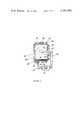
- FIG. 1depicts a cross sectional view of the present invention used as the evaporator section of a heat pipe.
- FIG. 2is a perspective view of a cooling panel using the present invention.
- the present inventionis depicted in FIG. 1 in conjunction with gravity dependent heat pipe 10 where sintered layer 22, similar in construction to but thinner than a conventional heat pipe wick, pump 12 connected to casing 11 at drain 14, and spray nozzle 16 cooperate to transfer heat from high power density surface 18.
- High power density surface 18is heated by some external device not shown.
- the externally generated heatpasses through casing 11 at surface 20 and in turn transfers heat to sintered layer 22 constructed as a thin evaporator layer with high density, high conductivity sintered material.
- Sintered surface 22disperses the heat over its volume by its thermal conductivity characteristics.
- Sintered layer 22is bonded to the surface of casing 11. Other areas of casing 11 are cooled by conventional cooling pipes 24 in which liquid is flowing.
- Drain 14penetrates casing 11 at its lowest point and is connected to pump 12 by inlet line 26. Pump 12 is connected to spray nozzle 16 by means of outlet line 28. Spray nozzle 16 penetrates casing 11 and is directed so that spray 29 will cover the entire back side of sintered layer 22. Vacuum closure 30 penetrates casing 11 to permit evacuation of non-condensable gases from the heat pipe and loading with liquid.
- the thermal characteristics of sintered layer 22are such that it also conducts heat outwardly into contact with the liquid trapped in all its pores to enhance the vaporizing action.
- Important benefits of the inventionare the ability to keep sintered layer 22 saturated with liquid and to overcome with mechanical force the interference with liquid flow by the vapor being emitted from sintered layer 22.
- spray nozzle 16should be designed to yield a droplet pattern on sintered layer 22 with droplet edge to edge spacing of less than two millimeters, and both the density and the thermal conductivity of sintered surface 22 should be high.
- a density of 40 to 60 percent of theoretical density and a pore size of 1 to 25 micronis preferred.
- FIG. 2An alternate embodiment of the invention is shown in FIG. 2, where vapor generating cooling panel 40 is sprayed with liquid from several nozzles 42 fed by pump 44.
- Capillary layer 46is constructed of dense sintered metal to yield both high thermal conductivity and strong capillary pumping of liquid. Both of these characteristics are omnidirectional, but since heat is supplied at structural panel 48 to which capillary layer 46 is bonded, the heat flow is essentially in the direction from panel 48 to layer 46.
- Structural panel 48is itself heated from a heat source (not shown) which could be any common source, such as waste heat from any mechanical, chemical, or electrical process.
- capillary layer 46Flows within capillary layer 46 are essentially perpendicular to the surface since the complete wetting of layer 46 by spray from nozzles 42 neutralizes capillary forces which would otherwise act parallel to the plane of the surface. Essentially, liquid movement is in toward panel 48 and vapor moves out toward the exposed surface of capillary layer 46. Once free of the surface, vapor 50 rises in the atmosphere.
- Nozzles 42are fed by pump 44 by means of manifold 43.
- Pump 44draws liquid through pipe 52 from tank 54.
- Tank 54is originally filled and replenished through pipe 56 from a liquid source (not shown). Since an excess of liquid will, however, be sprayed onto surface 46, drip pan 58 is used to catch the runoff and return it to tank 54 by means of pipe 60.
- the capillary layerneed not be planar, and could be the outside surface of a pipe or the surfaces of a group of tubes within a heat exchanger.
Landscapes
- Engineering & Computer Science (AREA)
- Life Sciences & Earth Sciences (AREA)
- Sustainable Development (AREA)
- Physics & Mathematics (AREA)
- Thermal Sciences (AREA)
- Mechanical Engineering (AREA)
- General Engineering & Computer Science (AREA)
Abstract
Description
Claims (5)
Priority Applications (1)
| Application Number | Priority Date | Filing Date | Title |
|---|---|---|---|
| US06/220,020US4352392A (en) | 1980-12-24 | 1980-12-24 | Mechanically assisted evaporator surface |
Applications Claiming Priority (1)
| Application Number | Priority Date | Filing Date | Title |
|---|---|---|---|
| US06/220,020US4352392A (en) | 1980-12-24 | 1980-12-24 | Mechanically assisted evaporator surface |
Publications (1)
| Publication Number | Publication Date |
|---|---|
| US4352392Atrue US4352392A (en) | 1982-10-05 |
Family
ID=22821716
Family Applications (1)
| Application Number | Title | Priority Date | Filing Date |
|---|---|---|---|
| US06/220,020Expired - LifetimeUS4352392A (en) | 1980-12-24 | 1980-12-24 | Mechanically assisted evaporator surface |
Country Status (1)
| Country | Link |
|---|---|
| US (1) | US4352392A (en) |
Cited By (55)
| Publication number | Priority date | Publication date | Assignee | Title |
|---|---|---|---|---|
| US4492266A (en)* | 1981-10-22 | 1985-01-08 | Lockheed Missiles & Space Company, Inc. | Manifolded evaporator for pump-assisted heat pipe |
| US4547130A (en)* | 1984-02-13 | 1985-10-15 | Thermacore, Inc. | Capillary input for pumps |
| US4643250A (en)* | 1985-07-01 | 1987-02-17 | Sundstrand Corporation | Fluid jet impingement heat exchanger for operation in zero gravity conditions |
| US4690210A (en)* | 1985-07-01 | 1987-09-01 | Sundstrand Corporation | Fluid jet impingement heat exchanger for operation in zero gravity conditions |
| US5031408A (en)* | 1988-04-19 | 1991-07-16 | The Boeing Company | Film deposition system |
| USH971H (en) | 1988-10-24 | 1991-10-01 | The United States Of America As Represented By The Secretary Of The Air Force | Regidized porous material and method |
| US5103897A (en)* | 1991-06-05 | 1992-04-14 | Martin Marietta Corporation | Flowrate controller for hybrid capillary/mechanical two-phase thermal loops |
| US5183104A (en)* | 1989-06-16 | 1993-02-02 | Digital Equipment Corporation | Closed-cycle expansion-valve impingement cooling system |
| US5515910A (en)* | 1993-05-03 | 1996-05-14 | Micro Control System | Apparatus for burn-in of high power semiconductor devices |
| US5527494A (en)* | 1989-02-24 | 1996-06-18 | Orniat Turbines (1965) Ltd. | Apparatus for liquid-gas contact |
| USRE35350E (en)* | 1992-11-16 | 1996-10-08 | Shahar; Arie | Method and apparatus for measuring surface distances from a reference plane |
| US5907473A (en)* | 1997-04-04 | 1999-05-25 | Raytheon Company | Environmentally isolated enclosure for electronic components |
| US5924482A (en)* | 1997-10-29 | 1999-07-20 | Motorola, Inc. | Multi-mode, two-phase cooling module |
| US6058711A (en)* | 1996-08-12 | 2000-05-09 | Centre National D'etudes Spatiales | Capillary evaporator for diphasic loop of energy transfer between a hot source and a cold source |
| US6167948B1 (en) | 1996-11-18 | 2001-01-02 | Novel Concepts, Inc. | Thin, planar heat spreader |
| US6205799B1 (en)* | 1999-09-13 | 2001-03-27 | Hewlett-Packard Company | Spray cooling system |
| US6209626B1 (en)* | 1999-01-11 | 2001-04-03 | Intel Corporation | Heat pipe with pumping capabilities and use thereof in cooling a device |
| US6484521B2 (en) | 2001-02-22 | 2002-11-26 | Hewlett-Packard Company | Spray cooling with local control of nozzles |
| US6550263B2 (en) | 2001-02-22 | 2003-04-22 | Hp Development Company L.L.P. | Spray cooling system for a device |
| US6595014B2 (en) | 2001-02-22 | 2003-07-22 | Hewlett-Packard Development Company, L.P. | Spray cooling system with cooling regime detection |
| US6604571B1 (en) | 2002-04-11 | 2003-08-12 | General Dynamics Land Systems, Inc. | Evaporative cooling of electrical components |
| US6644058B2 (en) | 2001-02-22 | 2003-11-11 | Hewlett-Packard Development Company, L.P. | Modular sprayjet cooling system |
| US20040040328A1 (en)* | 2001-02-22 | 2004-03-04 | Patel Chandrakant D. | Self-contained spray cooling module |
| US20040050545A1 (en)* | 2002-09-13 | 2004-03-18 | Tilton Charles L. | Dynamic spray system |
| US6708515B2 (en) | 2001-02-22 | 2004-03-23 | Hewlett-Packard Development Company, L.P. | Passive spray coolant pump |
| US20040076260A1 (en)* | 2002-01-31 | 2004-04-22 | Charles Jr Harry K. | X-ray source and method for more efficiently producing selectable x-ray frequencies |
| US20040194492A1 (en)* | 2002-09-27 | 2004-10-07 | Isothermal Systems Research | Hotspot coldplate spray cooling system |
| US6889515B2 (en) | 2002-11-12 | 2005-05-10 | Isothermal Systems Research, Inc. | Spray cooling system |
| US20050183844A1 (en)* | 2004-02-24 | 2005-08-25 | Isothermal Systems Research | Hotspot spray cooling |
| US20050185378A1 (en)* | 2004-02-24 | 2005-08-25 | Isothermal Systems Research | Etched open microchannel spray cooling |
| US20050241804A1 (en)* | 2004-04-29 | 2005-11-03 | Foxconn Technology Co.,Ltd | Liquid cooling device |
| US20060005953A1 (en)* | 2004-06-25 | 2006-01-12 | Foxconn Technology Co., Ltd | Liquid cooling device |
| US6990816B1 (en) | 2004-12-22 | 2006-01-31 | Advanced Cooling Technologies, Inc. | Hybrid capillary cooling apparatus |
| US20070144708A1 (en)* | 2005-12-22 | 2007-06-28 | Tilton Charles L | Passive Fluid Recovery System |
| US7240500B2 (en) | 2003-09-17 | 2007-07-10 | Hewlett-Packard Development Company, L.P. | Dynamic fluid sprayjet delivery system |
| US7331377B1 (en) | 2004-01-30 | 2008-02-19 | Isothermal Systems Research, Inc. | Diamond foam spray cooling system |
| US20100107657A1 (en)* | 2007-02-23 | 2010-05-06 | Vistakula Kranthi K | Apparel with heating and cooling capabilities |
| US20100243210A1 (en)* | 2003-03-20 | 2010-09-30 | Rosenfeld John H | Capillary assisted loop thermosiphon apparatus |
| US7992626B1 (en)* | 2004-01-30 | 2011-08-09 | Parker-Hannifin Corporation | Combination spray and cold plate thermal management system |
| US20120205076A1 (en)* | 2011-02-11 | 2012-08-16 | Tai-Her Yang | Temperature equalization apparatus jetting fluid for thermal conduction used in electrical equipment |
| US20120205071A1 (en)* | 2011-02-11 | 2012-08-16 | Tai-Her Yang | Temperature equalization apparatus jetting fluid for thermal conduction used in electrical equipment |
| US20130032311A1 (en)* | 2011-08-01 | 2013-02-07 | Avijit Bhunia | System for Using Active and Passive Cooling for High Power Thermal Management |
| US8671697B2 (en) | 2010-12-07 | 2014-03-18 | Parker-Hannifin Corporation | Pumping system resistant to cavitation |
| EP3171111A1 (en)* | 2015-11-23 | 2017-05-24 | L-3 Communications Corporation | Evaporator assembly |
| US9832913B2 (en) | 2011-06-27 | 2017-11-28 | Ebullient, Inc. | Method of operating a cooling apparatus to provide stable two-phase flow |
| US9848509B2 (en) | 2011-06-27 | 2017-12-19 | Ebullient, Inc. | Heat sink module |
| US9852963B2 (en) | 2014-10-27 | 2017-12-26 | Ebullient, Inc. | Microprocessor assembly adapted for fluid cooling |
| US9854715B2 (en) | 2011-06-27 | 2017-12-26 | Ebullient, Inc. | Flexible two-phase cooling system |
| US9854714B2 (en) | 2011-06-27 | 2017-12-26 | Ebullient, Inc. | Method of absorbing sensible and latent heat with series-connected heat sinks |
| US9901008B2 (en) | 2014-10-27 | 2018-02-20 | Ebullient, Inc. | Redundant heat sink module |
| US9901013B2 (en) | 2011-06-27 | 2018-02-20 | Ebullient, Inc. | Method of cooling series-connected heat sink modules |
| US10184699B2 (en) | 2014-10-27 | 2019-01-22 | Ebullient, Inc. | Fluid distribution unit for two-phase cooling system |
| US20200232684A1 (en)* | 2015-09-17 | 2020-07-23 | Purdue Research Foundation | Devices, systems, and methods for the rapid transient cooling of pulsed heat sources |
| US11015879B2 (en) | 2016-06-16 | 2021-05-25 | Teledyne Scientific & Imaging, Llc | Interface-free thermal management system for high power devices co-fabricated with electronic circuit |
| US11906218B2 (en) | 2014-10-27 | 2024-02-20 | Ebullient, Inc. | Redundant heat sink module |
Citations (9)
| Publication number | Priority date | Publication date | Assignee | Title |
|---|---|---|---|---|
| US2643282A (en)* | 1949-04-13 | 1953-06-23 | Albert D Greene | Electronic equipment cooling means |
| US2901893A (en)* | 1956-05-24 | 1959-09-01 | Alvin R Saltzman | Thermal diffusion desorption cooling system |
| US3095255A (en)* | 1960-04-25 | 1963-06-25 | Carrier Corp | Heat exchange apparatus of the evaporative type |
| US3838997A (en)* | 1971-10-08 | 1974-10-01 | Heye H | Method and apparatus for the evaporative cooling tools of glass forming machines |
| US3842596A (en)* | 1970-07-10 | 1974-10-22 | V Gray | Methods and apparatus for heat transfer in rotating bodies |
| US3852806A (en)* | 1973-05-02 | 1974-12-03 | Gen Electric | Nonwicked heat-pipe cooled power semiconductor device assembly having enhanced evaporated surface heat pipes |
| SU464768A1 (en)* | 1973-05-23 | 1975-03-25 | Ленинградский Институт Точной Механики И Оптики | Installation for evaporative cooling of a heat-generating source |
| US3989095A (en)* | 1972-12-28 | 1976-11-02 | Ckd Praha, Oborovy Podnik | Semi conductor cooling system |
| US3999400A (en)* | 1970-07-10 | 1976-12-28 | Gray Vernon H | Rotating heat pipe for air-conditioning |
- 1980
- 1980-12-24USUS06/220,020patent/US4352392A/ennot_activeExpired - Lifetime
Patent Citations (9)
| Publication number | Priority date | Publication date | Assignee | Title |
|---|---|---|---|---|
| US2643282A (en)* | 1949-04-13 | 1953-06-23 | Albert D Greene | Electronic equipment cooling means |
| US2901893A (en)* | 1956-05-24 | 1959-09-01 | Alvin R Saltzman | Thermal diffusion desorption cooling system |
| US3095255A (en)* | 1960-04-25 | 1963-06-25 | Carrier Corp | Heat exchange apparatus of the evaporative type |
| US3842596A (en)* | 1970-07-10 | 1974-10-22 | V Gray | Methods and apparatus for heat transfer in rotating bodies |
| US3999400A (en)* | 1970-07-10 | 1976-12-28 | Gray Vernon H | Rotating heat pipe for air-conditioning |
| US3838997A (en)* | 1971-10-08 | 1974-10-01 | Heye H | Method and apparatus for the evaporative cooling tools of glass forming machines |
| US3989095A (en)* | 1972-12-28 | 1976-11-02 | Ckd Praha, Oborovy Podnik | Semi conductor cooling system |
| US3852806A (en)* | 1973-05-02 | 1974-12-03 | Gen Electric | Nonwicked heat-pipe cooled power semiconductor device assembly having enhanced evaporated surface heat pipes |
| SU464768A1 (en)* | 1973-05-23 | 1975-03-25 | Ленинградский Институт Точной Механики И Оптики | Installation for evaporative cooling of a heat-generating source |
Non-Patent Citations (4)
| Title |
|---|
| Bahelaar et al., E. J. Heat Pipe for Chip Cooling, IBM Tech. Discl. Bulletin, vol. 14, No. 9, 2_72.* |
| Hwang et al., U. P. Evaporation Cooling Module, IBM Tech. Discl. Bulletin, vol. 21, No. 10, 3/79.* |
| R. A. Freggens, in "Experimental Determination of Wick Properties for Heat Pipe Applications", 4th IECEC, Washington, D.C., Sep. 1969.* |
| Sachar, K. S. Integrated Circuit Cooling Device, IBM Tech. Discl. Bulletin, vol. 19, No. 2, 7/76.* |
Cited By (82)
| Publication number | Priority date | Publication date | Assignee | Title |
|---|---|---|---|---|
| US4492266A (en)* | 1981-10-22 | 1985-01-08 | Lockheed Missiles & Space Company, Inc. | Manifolded evaporator for pump-assisted heat pipe |
| US4547130A (en)* | 1984-02-13 | 1985-10-15 | Thermacore, Inc. | Capillary input for pumps |
| US4643250A (en)* | 1985-07-01 | 1987-02-17 | Sundstrand Corporation | Fluid jet impingement heat exchanger for operation in zero gravity conditions |
| US4690210A (en)* | 1985-07-01 | 1987-09-01 | Sundstrand Corporation | Fluid jet impingement heat exchanger for operation in zero gravity conditions |
| US5031408A (en)* | 1988-04-19 | 1991-07-16 | The Boeing Company | Film deposition system |
| USH971H (en) | 1988-10-24 | 1991-10-01 | The United States Of America As Represented By The Secretary Of The Air Force | Regidized porous material and method |
| US5320866A (en)* | 1988-10-24 | 1994-06-14 | The United States Of America As Represented By The Secretary Of The Air Force | Method of wet coating a ceramic substrate with a liquid suspension of metallic particles and binder applying similar dry metallic particles onto the wet surface, then drying and heat treating the article |
| US5527494A (en)* | 1989-02-24 | 1996-06-18 | Orniat Turbines (1965) Ltd. | Apparatus for liquid-gas contact |
| US5183104A (en)* | 1989-06-16 | 1993-02-02 | Digital Equipment Corporation | Closed-cycle expansion-valve impingement cooling system |
| US5103897A (en)* | 1991-06-05 | 1992-04-14 | Martin Marietta Corporation | Flowrate controller for hybrid capillary/mechanical two-phase thermal loops |
| USRE35350E (en)* | 1992-11-16 | 1996-10-08 | Shahar; Arie | Method and apparatus for measuring surface distances from a reference plane |
| US5515910A (en)* | 1993-05-03 | 1996-05-14 | Micro Control System | Apparatus for burn-in of high power semiconductor devices |
| US5579826A (en)* | 1993-05-03 | 1996-12-03 | Micro Control Company | Method for burn-in of high power semiconductor devices |
| US6058711A (en)* | 1996-08-12 | 2000-05-09 | Centre National D'etudes Spatiales | Capillary evaporator for diphasic loop of energy transfer between a hot source and a cold source |
| US6167948B1 (en) | 1996-11-18 | 2001-01-02 | Novel Concepts, Inc. | Thin, planar heat spreader |
| US5907473A (en)* | 1997-04-04 | 1999-05-25 | Raytheon Company | Environmentally isolated enclosure for electronic components |
| US6139361A (en)* | 1997-04-04 | 2000-10-31 | Raytheon Company | Hermetic connector for a closed compartment |
| US5924482A (en)* | 1997-10-29 | 1999-07-20 | Motorola, Inc. | Multi-mode, two-phase cooling module |
| US6209626B1 (en)* | 1999-01-11 | 2001-04-03 | Intel Corporation | Heat pipe with pumping capabilities and use thereof in cooling a device |
| US6205799B1 (en)* | 1999-09-13 | 2001-03-27 | Hewlett-Packard Company | Spray cooling system |
| US6457321B1 (en) | 1999-09-13 | 2002-10-01 | Hewlett-Packard Company | Spray cooling system |
| US6612120B2 (en) | 2001-02-22 | 2003-09-02 | Hewlett-Packard Development Company, L.P. | Spray cooling with local control of nozzles |
| US7082778B2 (en) | 2001-02-22 | 2006-08-01 | Hewlett-Packard Development Company, L.P. | Self-contained spray cooling module |
| US6595014B2 (en) | 2001-02-22 | 2003-07-22 | Hewlett-Packard Development Company, L.P. | Spray cooling system with cooling regime detection |
| US6550263B2 (en) | 2001-02-22 | 2003-04-22 | Hp Development Company L.L.P. | Spray cooling system for a device |
| US6484521B2 (en) | 2001-02-22 | 2002-11-26 | Hewlett-Packard Company | Spray cooling with local control of nozzles |
| US6644058B2 (en) | 2001-02-22 | 2003-11-11 | Hewlett-Packard Development Company, L.P. | Modular sprayjet cooling system |
| US20040040328A1 (en)* | 2001-02-22 | 2004-03-04 | Patel Chandrakant D. | Self-contained spray cooling module |
| US6817196B2 (en) | 2001-02-22 | 2004-11-16 | Hewlett-Packard Development Company, L.P. | Spray cooling system with cooling regime detection |
| US6708515B2 (en) | 2001-02-22 | 2004-03-23 | Hewlett-Packard Development Company, L.P. | Passive spray coolant pump |
| US6817204B2 (en) | 2001-02-22 | 2004-11-16 | Hewlett-Packard Development Company, L.P. | Modular sprayjet cooling system |
| US20040118143A1 (en)* | 2001-02-22 | 2004-06-24 | Bash Cullen E. | Modular sprayjet cooling system |
| US20040076260A1 (en)* | 2002-01-31 | 2004-04-22 | Charles Jr Harry K. | X-ray source and method for more efficiently producing selectable x-ray frequencies |
| US7186022B2 (en)* | 2002-01-31 | 2007-03-06 | The Johns Hopkins University | X-ray source and method for more efficiently producing selectable x-ray frequencies |
| US6604571B1 (en) | 2002-04-11 | 2003-08-12 | General Dynamics Land Systems, Inc. | Evaporative cooling of electrical components |
| US20040050545A1 (en)* | 2002-09-13 | 2004-03-18 | Tilton Charles L. | Dynamic spray system |
| US6880350B2 (en) | 2002-09-13 | 2005-04-19 | Isothermal Systems Research, Inc. | Dynamic spray system |
| US20040194492A1 (en)* | 2002-09-27 | 2004-10-07 | Isothermal Systems Research | Hotspot coldplate spray cooling system |
| US7159414B2 (en) | 2002-09-27 | 2007-01-09 | Isothermal Systems Research Inc. | Hotspot coldplate spray cooling system |
| US6889515B2 (en) | 2002-11-12 | 2005-05-10 | Isothermal Systems Research, Inc. | Spray cooling system |
| US20100243210A1 (en)* | 2003-03-20 | 2010-09-30 | Rosenfeld John H | Capillary assisted loop thermosiphon apparatus |
| US8627879B2 (en)* | 2003-03-20 | 2014-01-14 | Thermal Corp. | Capillary assisted loop thermosiphon apparatus |
| US20110042045A1 (en)* | 2003-03-20 | 2011-02-24 | Rosenfeld John H | Capillary assisted loop thermosiphon apparatus |
| US7823629B2 (en)* | 2003-03-20 | 2010-11-02 | Thermal Corp. | Capillary assisted loop thermosiphon apparatus |
| US7240500B2 (en) | 2003-09-17 | 2007-07-10 | Hewlett-Packard Development Company, L.P. | Dynamic fluid sprayjet delivery system |
| US7992626B1 (en)* | 2004-01-30 | 2011-08-09 | Parker-Hannifin Corporation | Combination spray and cold plate thermal management system |
| US7331377B1 (en) | 2004-01-30 | 2008-02-19 | Isothermal Systems Research, Inc. | Diamond foam spray cooling system |
| US6952346B2 (en) | 2004-02-24 | 2005-10-04 | Isothermal Systems Research, Inc | Etched open microchannel spray cooling |
| US20050185378A1 (en)* | 2004-02-24 | 2005-08-25 | Isothermal Systems Research | Etched open microchannel spray cooling |
| US20050183844A1 (en)* | 2004-02-24 | 2005-08-25 | Isothermal Systems Research | Hotspot spray cooling |
| US20050241804A1 (en)* | 2004-04-29 | 2005-11-03 | Foxconn Technology Co.,Ltd | Liquid cooling device |
| US7143815B2 (en)* | 2004-04-29 | 2006-12-05 | Foxconn Technology Co., Ltd. | Liquid cooling device |
| US20060005953A1 (en)* | 2004-06-25 | 2006-01-12 | Foxconn Technology Co., Ltd | Liquid cooling device |
| US6990816B1 (en) | 2004-12-22 | 2006-01-31 | Advanced Cooling Technologies, Inc. | Hybrid capillary cooling apparatus |
| WO2007076090A3 (en)* | 2005-12-22 | 2008-03-27 | Isothermal Systems Res Inc | Passive fluid recovery system |
| US7717162B2 (en) | 2005-12-22 | 2010-05-18 | Isothermal Systems Research, Inc. | Passive fluid recovery system |
| US7779896B2 (en) | 2005-12-22 | 2010-08-24 | Parker-Hannifin Corporation | Passive fluid recovery system |
| US20080066892A1 (en)* | 2005-12-22 | 2008-03-20 | Isothermal Systems Research, Inc. | Passive Fluid Recovery System |
| US20070144708A1 (en)* | 2005-12-22 | 2007-06-28 | Tilton Charles L | Passive Fluid Recovery System |
| US20100107657A1 (en)* | 2007-02-23 | 2010-05-06 | Vistakula Kranthi K | Apparel with heating and cooling capabilities |
| US8671697B2 (en) | 2010-12-07 | 2014-03-18 | Parker-Hannifin Corporation | Pumping system resistant to cavitation |
| US20120205071A1 (en)* | 2011-02-11 | 2012-08-16 | Tai-Her Yang | Temperature equalization apparatus jetting fluid for thermal conduction used in electrical equipment |
| US20120205076A1 (en)* | 2011-02-11 | 2012-08-16 | Tai-Her Yang | Temperature equalization apparatus jetting fluid for thermal conduction used in electrical equipment |
| US9648781B2 (en)* | 2011-02-11 | 2017-05-09 | Tai-Her Yang | Temperature equalization apparatus jetting fluid for thermal conduction used in electrical equipment |
| US10051762B2 (en)* | 2011-02-11 | 2018-08-14 | Tai-Her Yang | Temperature equalization apparatus jetting fluid for thermal conduction used in electrical equipment |
| US9854715B2 (en) | 2011-06-27 | 2017-12-26 | Ebullient, Inc. | Flexible two-phase cooling system |
| US9854714B2 (en) | 2011-06-27 | 2017-12-26 | Ebullient, Inc. | Method of absorbing sensible and latent heat with series-connected heat sinks |
| US9832913B2 (en) | 2011-06-27 | 2017-11-28 | Ebullient, Inc. | Method of operating a cooling apparatus to provide stable two-phase flow |
| US9848509B2 (en) | 2011-06-27 | 2017-12-19 | Ebullient, Inc. | Heat sink module |
| US9901013B2 (en) | 2011-06-27 | 2018-02-20 | Ebullient, Inc. | Method of cooling series-connected heat sink modules |
| US20130032311A1 (en)* | 2011-08-01 | 2013-02-07 | Avijit Bhunia | System for Using Active and Passive Cooling for High Power Thermal Management |
| US10006720B2 (en)* | 2011-08-01 | 2018-06-26 | Teledyne Scientific & Imaging, Llc | System for using active and passive cooling for high power thermal management |
| US9901008B2 (en) | 2014-10-27 | 2018-02-20 | Ebullient, Inc. | Redundant heat sink module |
| US9852963B2 (en) | 2014-10-27 | 2017-12-26 | Ebullient, Inc. | Microprocessor assembly adapted for fluid cooling |
| US10184699B2 (en) | 2014-10-27 | 2019-01-22 | Ebullient, Inc. | Fluid distribution unit for two-phase cooling system |
| US11906218B2 (en) | 2014-10-27 | 2024-02-20 | Ebullient, Inc. | Redundant heat sink module |
| US20200232684A1 (en)* | 2015-09-17 | 2020-07-23 | Purdue Research Foundation | Devices, systems, and methods for the rapid transient cooling of pulsed heat sources |
| US11649995B2 (en)* | 2015-09-17 | 2023-05-16 | Purdue Research Foundation | Devices, systems, and methods for the rapid transient cooling of pulsed heat sources |
| US20170146273A1 (en)* | 2015-11-23 | 2017-05-25 | L-3 Communications Corporation | Evaporator Assembly |
| EP3171111A1 (en)* | 2015-11-23 | 2017-05-24 | L-3 Communications Corporation | Evaporator assembly |
| US11015879B2 (en) | 2016-06-16 | 2021-05-25 | Teledyne Scientific & Imaging, Llc | Interface-free thermal management system for high power devices co-fabricated with electronic circuit |
| US11022383B2 (en) | 2016-06-16 | 2021-06-01 | Teledyne Scientific & Imaging, Llc | Interface-free thermal management system for high power devices co-fabricated with electronic circuit |
Similar Documents
| Publication | Publication Date | Title |
|---|---|---|
| US4352392A (en) | Mechanically assisted evaporator surface | |
| US20190154353A1 (en) | Heat pipe having a wick with a hybrid profile | |
| US10704839B2 (en) | Temperature actuated capillary valve for loop heat pipe system | |
| US9696096B2 (en) | Loop heat pipe and electronic equipment using the same | |
| US5894887A (en) | Ceramic dome temperature control using heat pipe structure and method | |
| US3746081A (en) | Heat transfer device | |
| US20120137718A1 (en) | Cooling apparatus and electronic apparatus | |
| US3450195A (en) | Multiple circuit heat transfer device | |
| US6241008B1 (en) | Capillary evaporator | |
| JPH07505703A (en) | Plate heat exchanger | |
| US10302367B2 (en) | Non-metallic vapor chambers | |
| KR102442845B1 (en) | Vapor chamber | |
| EP3171111A1 (en) | Evaporator assembly | |
| US3828849A (en) | Heat transfer device | |
| JPH11304381A (en) | heat pipe | |
| JP2904199B2 (en) | Evaporator for capillary pump loop and heat exchange method thereof | |
| JP4193188B2 (en) | Thin composite plate heat pipe | |
| JPH11330329A (en) | Vaporizing cooling device | |
| KR100865718B1 (en) | Heat pipe for long distance calorie transportation | |
| WO2018072315A1 (en) | Internal heat exchange component of absorption refrigeration unit, and absorption refrigeration unit and matrix | |
| US3994336A (en) | Transformer for heat pipes | |
| WO2022004616A1 (en) | Heat transfer device | |
| US20020074108A1 (en) | Horizontal two-phase loop thermosyphon with capillary structures | |
| JP2007147194A (en) | Heat pipe and its manufacturing method | |
| JPS62233686A (en) | heat transfer device |
Legal Events
| Date | Code | Title | Description |
|---|---|---|---|
| STCF | Information on status: patent grant | Free format text:PATENTED CASE | |
| MAFP | Maintenance fee payment | Free format text:PAYMENT OF MAINTENANCE FEE, 4TH YEAR, PL 96-517 (ORIGINAL EVENT CODE: M170); ENTITY STATUS OF PATENT OWNER: SMALL ENTITY Year of fee payment:4 | |
| FEPP | Fee payment procedure | Free format text:PAYOR NUMBER ASSIGNED (ORIGINAL EVENT CODE: ASPN); ENTITY STATUS OF PATENT OWNER: SMALL ENTITY | |
| MAFP | Maintenance fee payment | Free format text:PAYMENT OF MAINTENANCE FEE, 8TH YEAR, PL 96-517 (ORIGINAL EVENT CODE: M171); ENTITY STATUS OF PATENT OWNER: SMALL ENTITY Year of fee payment:8 | |
| MAFP | Maintenance fee payment | Free format text:PAYMENT OF MAINTENANCE FEE, 12TH YR, SMALL ENTITY (ORIGINAL EVENT CODE: M285); ENTITY STATUS OF PATENT OWNER: SMALL ENTITY Year of fee payment:12 | |
| FEPP | Fee payment procedure | Free format text:PAT HOLDER CLAIMS SMALL ENTITY STATUS - SMALL BUSINESS (ORIGINAL EVENT CODE: SM02); ENTITY STATUS OF PATENT OWNER: SMALL ENTITY | |
| AS | Assignment | Owner name:THERMAL CORP., DELAWARE Free format text:ASSIGNMENT OF ASSIGNORS INTEREST;ASSIGNOR:THERMACORE, INC.;REEL/FRAME:008613/0683 Effective date:19970709 |