US4351401A - Earth-boring drill bits - Google Patents
Earth-boring drill bitsDownload PDFInfo
- Publication number
- US4351401A US4351401AUS06/159,181US15918180AUS4351401AUS 4351401 AUS4351401 AUS 4351401AUS 15918180 AUS15918180 AUS 15918180AUS 4351401 AUS4351401 AUS 4351401A
- Authority
- US
- United States
- Prior art keywords
- bit
- cutters
- diamonds
- hard material
- preform
- Prior art date
- Legal status (The legal status is an assumption and is not a legal conclusion. Google has not performed a legal analysis and makes no representation as to the accuracy of the status listed.)
- Expired - Lifetime
Links
Images

Classifications
- E—FIXED CONSTRUCTIONS
- E21—EARTH OR ROCK DRILLING; MINING
- E21B—EARTH OR ROCK DRILLING; OBTAINING OIL, GAS, WATER, SOLUBLE OR MELTABLE MATERIALS OR A SLURRY OF MINERALS FROM WELLS
- E21B10/00—Drill bits
- E21B10/46—Drill bits characterised by wear resisting parts, e.g. diamond inserts
- E21B10/56—Button-type inserts
- E21B10/567—Button-type inserts with preformed cutting elements mounted on a distinct support, e.g. polycrystalline inserts
- E21B10/573—Button-type inserts with preformed cutting elements mounted on a distinct support, e.g. polycrystalline inserts characterised by support details, e.g. the substrate construction or the interface between the substrate and the cutting element
Definitions
- Diamond bitsemploying natural or synthetic diamonds positioned on the face of a drill shank and bonded to the shank in a matrix of a secondary abrasive, such as tungsten carbide, by means of a metal bond, are well known in the art.
- Drill bits formed according to the above procedureare subject to damage when used as bore-hole drill bits. Such damage results from localized destruction of the diamond matrix complex. When this occurs, the useful life of the bit may be terminated and salvage of the bit is required by separating the diamonds and tungsten carbide from the steel shank.
- a cutter preformis employed.
- the cutter preformmay be made as described in U.S. Pat. No. 3,745,623 or by molding mixtures of diamond particles, secondary abrasive particles, and particles of a metallic bonding agent employing the techniques of the above patents in suitable shaped molds, for example, by the hot press methods described in U.S. Pat. Nos. 3,841,852 and 3,871,840.
- a preformis preferred formed as in U.S. Pat. No. 3,745,623.
- the preformsare mounted in the body of the drill bit, such as described above, to be placed in spaced relation from the part adjacent to the central axis to close to gage of the bit.
- the arrangement of the preforms in the bitis such that on rotation of the bit about its axis, substantially the entire surface of the earth traversed by the bit on rotation is engaged by the preforms.
- the preformsare set at a negative rake and the preforms are backed by an adjacent portion of the body of the bit to take the thrust on the preform cutters imposed during drilling. Bending stresses are thus minimized, and, in a practical sense, avoided in the preforms.
- Provisionsare made to move the cuttings away from the preforms, the drilling fluid discharging from a fluid passage in the bit to provide a flushing action.
- channelsare provided in fluid communication with the passage in front of the cutter preforms. The channels extend across the face of the bit from the central bore to the gage of the bit. While, for some uses, the channels may be omitted, the channels, as in our preferred embodiments, aid in establishing the bit hydraulics to clean the face of the bit and flush the cuttings from the drilling region.
- the cuttersmay be set with a zero but preferably with a negative side rake, so as to provide for a snowplow effect to move the cutting to the outer gage of the bit.
- the channels in the preferred embodimentextend in front of the cutter preforms which are oriented as described above.
- the orientation of the rake and the flow of fluid through the channelsmove the cuttings to the annulus between the bit and bore hole to be carried up the annulus to the surface.
- the preform cuttersare carried in preformed sockets positioned in the base of the drill bit, preferably in a drill bit coated, for example, with metal-bonded secondary abrasives having a hardness value less than diamonds. Coating of the drill bit with such hard material is conventional, but in such case, the diamonds are mounted as described in the above patents. We prefer to prepare sockets in the drill, so oriented about the drill bit, and with the preforms so oriented in the sockets, as to give the pattern previously referred to.
- the cutters according to our inventionmay be mounted in preformed sockets formed in the matrix-coated drill, so formed as to orient the preforms which are mounted by insertion into the sockets, to provide the pattern and rakes described above.
- the preformsmay be mounted in receptacles positioned on studs which are inserted in sockets formed in the matrix-coated drill.
- the studs and socketsare formed so that on insertion of the studs in the receptacles, the preforms are oriented in the pattern and with the rakes described above.
- bits carrying the studsin relatively soft formations and to use the preforms mounted directly in the sockets for hard formations.
- cuttersin an array in the manner and for the purposes described above and more fully described below and to arrange the fluid channels to be positioned in front of the cutter arrays. This arrangement controls the flow pattern across the cutting surface in immediate proximity of the cutters and aids in removing cuttings and flushes them away from the cutters.
- One of the strengths of the mounted preform cutters according to the inventionis that, on destruction or other damages to a preform, the damaged preform may be removed and replaced without requiring the salvage of the entire bit.
- the above design of the diamond bit of our inventionis particularly suitable when using synthetic diamonds, such as are employed in the formation of the cutting elements described in U.S. Pat. No. 3,745,623.
- Such diamondsare weakened to a much greater degree than are natural diamonds at temperatures normally employed in production of drill bits by processes such as are described in U.S. Pat. Nos. 3,709,308; 3,824,083; and 3,757,879.
- Such processesentail exposing diamonds to temperatures which are used in the infiltration or hot press processes of the aforesaid patents.
- the temperatures employed in such proceduresare in the order of above about 2000° F., for example, 2150° F.
- Such temperatures, while suitable for natural diamondsare excessive for synthetic diamonds and weaken them excessively.
- the design of the drill bit of the inventionpermits the use of synthetic diamonds as well as natural diamonds in that the preforms using synthetic diamonds or natural diamonds may be formed at temperatures suitable for synthetic diamonds as is described in said U.S. Pat. No. 3,745,623.
- the design of the inventionthus permits the formation of the drill bit body at high temperatures and the formation of the preforms when using natural diamonds by the high temperature methods previously described, or when using synthetic diamonds by forming them at lower temperatures, for example, as described in U.S. Pat. No. 3,745,623.
- the preforms employing, for example, natural diamondsmay be formed by the hot press method referred to in U.S. Pat. No. 3,871,840 employing molds of suitable shape to form the preform of the desired geometric configuration.
- preformed cutters of the bitsmay generate cuttings so rapidly that they cannot be removed quickly enough by the circulating fluid from the hole bottom.
- preformed diamond cutterscan generate cuttings much faster than they can be removed by the fluid, resulting in the bit balling and virtually ceasing its drilling action.
- the placing of natural surface set penetration control diamonds in the bit matrix, at or near the gage of the bitcan drastically reduce and control the extent of penetration of the preformed cutters into the formation and the rate at which such cutters can drill the hole, permitting the circulating fluid issuing from the bit an opportunity to flush the cutters clean and convey the cuttings to the gage portion of the bit and the upwardly through the annulus surrounding the drilling string. As a result, balling of the bit is prevented, the bit performance being greatly improved.
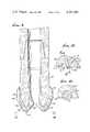
- FIG. 1is a view partly in elevation and partly in quarter section of an earth-boring bit according to our invention
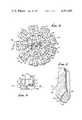
- FIG. 2is a plan view of the bottom of the bit taken on line 2--2 od FIG. 1;
- FIG. 3is a fragmentary section taken on line 3--3 of FIG. 1 with parts in elevation;
- FIG. 4is a section taken on line 4--4 of FIG. 3;
- FIG. 5is a section taken on line 5--5 of FIG. 4;
- FIG. 6is a fragmentary detail of FIG. 2 showing the side rake
- FIG. 7is a fragmentary section taken on line 7--7 of FIG. 2;
- FIG. 8is a section similar to FIG. 1 prior to installation of the studs
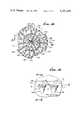
- FIG. 9is a vertical section of another form of a bit according to our invention.
- FIG. 10is a plan view taken on line 10--10 of FIG. 9;
- FIG. 11is an enlarged fragmentary detail taken on line 11 of FIG. 10;
- FIG. 12is a section taken on line 12--12 of FIG. 11;
- FIG. 13is a section taken on line 13--13 of FIG. 12.
- the tubular shank 1 of the bitis of conventional shape and is connected to the drill collar 2 and is coated internally and externally of the shank with a hard material 3, for example, such as metal-bonded tungsten carbide to form the face 4 of the bit section and the stabilizer section 5, as in prior art diamond drill bits used for earth bore-hole drilling.
- the hard coating 3 of the bitextends circumambiently about the central axis of the bit and is positioned between the gage 6 of the bit and across the face of the bit, the gage 6 being formed on the stabilizer section 5 of the hard coating.
- Sockets 7are positioned in the coating 3 spaced as herein described in the face 4 in accordance with a pattern for the purposes herein described.
- the cutters 8are mounted in the receptacles 9 carried on studs 14 positioned in sockets 7. We prefer, especially where the cutters are mounted in studs as described below, to form the face of the bit in steps 26 extending circumambiently about the face of the bit, as is described in a copending application filed jointly with applicant and another, Ser. No. 745,087.
- the stepsextend as a spiral from an inner portion 10 of the bit 1 to the portion of the face of the bit adjacent the gage 6, as will be more fully described below.
- the sockets in the case of the bit shown in FIGS. 1-7are formed in the angle between 1 and 31 on one step and the rise 30 of the adjacent step.
- each of the cuttersis positioned in a stud-mounted receptacle.
- the studs 14are formed with a receptacle 9 whose axis 16 is at an obtuse angle to the central axis of the stud 14.
- the studis formed of steel or material of similar physical properties and is coated with a hard surface coating 18 formed, for example, of material of the same kind as is used in the coating 3.
- the studmay be held securely in the socket by an interference fit or by brazing or other means of securing the stud in the socket.
- preform cutters 8Secured in the receptacles as by soldering or brazing are preform cutters 8 formed as described above. They may be of any desired geometric configuration to fit into the receptacle. For convenience, we prefer cylindrical wafers whose axial dimension is but a minor fraction of the diameter of the wafer. The acute angle 20 thus established a negative vertical cutting rake.
- the studs 14are provided with indexing means, for example, flat sections 21 (FIG. 4) so as to orient the studs, as is described below.
- indexing meansfor example, flat sections 21 (FIG. 4)
- the indexing meansare arranged to position the studs in a longitudinal array extending from adjacent the gage 6, across the face 4 towards the axis of the bit.
- the aforesaid longitudinal arrayextends circumambiently about the bit spaced from each other as is illustrated in FIGS. 1 and 2.
- the arraysare separated by fluid channels 23 which extend from the central portion 10 of the bit to the gage 6 of the bit at the stabilizer section 5, where they join the vertical grooves or fluid channels 24.
- the studsare positioned in each array and are spaced from each other in each array.
- the cuttersare arranged in each longitudinal array so that they are in staggered position with respect of the cutters in an adjacent array. The cutters in the arrays overlap each other in the sense that the portion of the earth, not traversed by a cutter of one array, is traversed by a cutter in the following array during rotation.
- the indexing flats in the socket and studare positioned so that the cutting face of the preform cutters in each array face in the same angular direction as the intended direction of rotation of the bit.
- the bitis designed for rotation in the usual manner by a clockwise rotation of the drilling string connected to the collar 2. This arrangement assures that all sections of the surface to be cut by the bit are traversed by a series of cutters during each revolution of the bit.
- a convenient arrangementis to position the sockets and studs in a generally spiral configuration extending from the center of the bit to the gage.
- studsmay be mounted in sockets formed in the face of the bit in any geometric form, for example, that shown in FIGS. 8 and 12, or in any form employed in the prior art, we prefer to mount the studs in sockets formed in the face as described and claimed in the copending application, Ser. No. 745,087.
- the faceis formed with a central portion 10 having a substantially circular perimeter 25.
- the portion of the face of the bit extending from the perimeter 25 to the gage 6 of the bitis formed with steps 26 in a spiral configuration.
- the spiral 27starts at the tangent 29 at the rise 30 and traverses the face 4 as a spiral to form the lands 31.
- the sockets 7are formed in the face of the bit with the axis of each socket intersecting the apex of the angle between the rise and the land of each step.
- the geometry of this arrangementallows the bit to constitute a jig to assure that the sockets will be in a spiral configuration.
- the positioning of the studs in the angle between the rise and the landaids in the protection of the preform. Impact loads are absorbed by the lands and rises where the studs are located.
- the preform cutter elementsfollow each other to cut the spaces which had been missed by the cutters of the preceding array. The result is that all portions of the earth are traversed by a series of cutters during each revolution of the bit.
- fluid channels 23which join the grooves 24 in the stabilizer section 5.
- the fluid channelsare in the form of grooves positioned between adjacent longitudinal arrays of cutters and extending adjacent to the face of the cutters in the array.
- Nozzles 34are positioned in the body of the face to connect with each channel.
- the nozzlesare connected by bores 35 with the central tubular bore of the shank 1. They are positioned at various radial distances from the center around the bit in a generally spiral arrangement.
- the flushing action of the fluid in the channels 23may be sufficient to clean the cutters 8 and prevent clogging.
- the face of the cuttersmay be set at a zero rake, that is perpendicular to the direction of rotation, or with the negative side rake described below.
- Drilling fluidis discharged from the nozzles 34 into the channels or fluid courses 23 to flush cuttings through such channels and from the adjacent region of the bit, the flow of the cutting laden fluid continuing upwardly through the fluid courses 24 and along the stabilizer 5, and through the annulus between the drill string and the bore-hole wall to the surface.
- the cuttersin addition to the vertical negative rake 20 shown in FIG. 3, may be set in a horizontal rake as shown in FIG. 6.
- the negative horizontal rake angle 36may be, for example about 1° to 10°, preferably about 20°.
- the effect of the negative sideways rakeis to introduce a snowplow effect and to move the cuttings toward the gage of the bit where they may be picked up by the circulating fluid and carried up the grooves 24 of the stabilizer 5.
- the vertical negative rake angle 20may be from about 4° to about 20°.
- the space taken by the receptacle and the preformsmakes impractical the positioning of a large multiple of preform cutting elements at the center of the bit.
- the problemis aggravated if any of the preforms are lost from the central portion because of damage occurring during use.
- It is preferred to supplement the cutting effect at the centerby locating surface set diamonds 37, either in a pattern or in random distribution, in the central portion of the hard material 3.
- Surface set diamondsare also positioned in the matrix 3 at the gage 6 where the side impacts during drilling are large, employing conventional techniques in setting the diamonds as described above.
- the hard metal coating or matrix 3is cast on the shank 1, the casting operation also forming the steps 26, sockets 7, fluid courses 23, 24 and fluid passages 34, 35 in the matrix.
- the diamonds 37 and diamonds 6a, 6b at the gage 5are surrounded by and embedded in the matrix to securely fasten the diamonds thereto.
- the preformed cutters 8, 9are then mounted in the sockets and secured therein.
- One of the features of the above constructionis that, should any one or more of the preform cutters be destroyed or the studs damaged, they may be removed; and a new stud and preform may be inserted.
- cutters of our inventionwhich is the presently preferred form, especially for use in hard formations, employs preforms mounted directly in position on the face of the bit.
- the bitis formed by a shank 101. coated as in the form of FIG. 1 by a hard coating 102.
- the face of the bit 103is of generally conical shape faring into the central opening 104.
- the central openingmay be the form of a threefold manifold with three branches 104 communicating with channels 105 extending to and communicating with the vertical grooves or fluid courses 107 in the stabilizer section 108 of the drill bit.
- protuberances 109On the face of the bit are formed protuberances 109 spaced in longitudinal arrays about the face of the bit.
- Each of the protuberanceshas an extension 110 leading from a socket 111 in which is mounted a preform cutter 112 of the above composition, the protuberance and socket being preformed.
- the entire back of the preformis supported by the wall of the socket 111 and the extension 110 which acts as a receptacle to receive the preform.
- the receptaclessupport the cutters with both vertical and horizontal rakes as is described for the cutters of FIGS. 1-7.
- the preformis mounted with a vertical negative rake 120 and, as is shown in FIG. 11, with a horizontal negative rake 136.
- the rake anglesmay be as described above for the forms of FIGS. 1-8.
- the protuberances in the hard materialextend from the periphery of the preforms 112 to the adjacent face of the bit.
- the protuberances 109are spaced in a longitudinal array from each other adjacent the channels 105, about the face of the bit.
- the protuberances and their contained receptaclesare spaced from each other in arrays, as is described for the form of FIGS. 1-8.
- the cutters positioned in the receptacles in the protuberancesare thus arrayed in a staggered overlapping arrangement with respect of the cutters in the protuberances in adjacent longitudinal arrays, similar to the arrangement of the stud supported preforms.
- the cutting surface of the cuttersfaces in the same angular direction as the direction of rotation of the bit.
- Fluid channels 105are positioned in front of the array of cutters 112. The fluid which is fed through the central bore of the tubular drill shank 101 discharges into the manifold 104 and thus through the channel 105 and 107 to flush the cuttings, which have been moved towards the gage 106, upward into the surrounding annulus.
- the cuttersare preforms which may be replaced as they are damaged or lost. They permit the cutters to be placed in receptacles formed in the hard coating of the diamond bit, in a predetermined array to efficiently cut an entire surface.
- the preformsmay use fine primary abrasives such as diamonds or equivalent hard abrasive particles in a preform arranged in a predetermined array on the bit.
- the use of such preforms mounted in a pattern to cover substantially the entire surface to be cut, but which would permit replacement of individual damages cutters,has the advantage that a worn bit may be readily repaired and need not be discarded or require salvage.
- the inventionprovides for a support which preserves the integrity of the preforms.
- surface set diamonds 6a, 6bare positioned in the matrix 3 at the gage 6. As shown in FIG. 10, surface set control diamonds 6a are located in the matrix at the gage 6 itself. Others surface set diamonds 6b may be disposed immediately inwardly of the gage, the dimaonds 6a, 6b extending arcuately around and near the gage. If the design of the bit requires, a large number of such surface set diamonds 6a, 6b can be embedded in the matrix, the extent of projection of such diamonds from the matrix being much less than the extent of projection of the preformed cutters 112. Thus, the maximum penetration of the preformed cutters 112 into the formation is controlled by the extent of penetration of the surface set control diamonds 6a, 6b into the formation, before the matrix face of the bit engages the formation.
Landscapes
- Engineering & Computer Science (AREA)
- Life Sciences & Earth Sciences (AREA)
- Mining & Mineral Resources (AREA)
- Geology (AREA)
- Mechanical Engineering (AREA)
- Physics & Mathematics (AREA)
- Environmental & Geological Engineering (AREA)
- Fluid Mechanics (AREA)
- Chemical & Material Sciences (AREA)
- Crystallography & Structural Chemistry (AREA)
- General Life Sciences & Earth Sciences (AREA)
- Geochemistry & Mineralogy (AREA)
- Earth Drilling (AREA)
Abstract
Description
This application is a division of application Ser. No. 913,571, filed June 8, 1978, for "Earth Boring Drill Bits", now U.S. Pat. No. 4,244,432, which is a continuation of application Ser. No. 704,424, filed July 12, 1976, for "Earth-Boring Drill Bits", now abandoned.
Diamond bits employing natural or synthetic diamonds positioned on the face of a drill shank and bonded to the shank in a matrix of a secondary abrasive, such as tungsten carbide, by means of a metal bond, are well known in the art.
There are two general types: One in which the diamonds usually of very small gage are randomly distributed in the matrix; another type contains diamonds, usually of larger size, positioned in the surface of the drill shank in a predetermined pattern, referred to as surface set. (see U.S. Pat. Nos. 3,709,308; 3,825,083; 3,871,840; 3,757,878; and 3,757,879.)
Drill bits formed according to the above procedure are subject to damage when used as bore-hole drill bits. Such damage results from localized destruction of the diamond matrix complex. When this occurs, the useful life of the bit may be terminated and salvage of the bit is required by separating the diamonds and tungsten carbide from the steel shank.
Instead of using individual diamond particles distributed either in random orientation in the secondary abrasive matrix, such as tungsten carbide with a metallic bonding agent, or as surface set bits, a cutter preform is employed. The cutter preform may be made as described in U.S. Pat. No. 3,745,623 or by molding mixtures of diamond particles, secondary abrasive particles, and particles of a metallic bonding agent employing the techniques of the above patents in suitable shaped molds, for example, by the hot press methods described in U.S. Pat. Nos. 3,841,852 and 3,871,840. A preform is preferred formed as in U.S. Pat. No. 3,745,623. According to the invention, the preforms are mounted in the body of the drill bit, such as described above, to be placed in spaced relation from the part adjacent to the central axis to close to gage of the bit. The arrangement of the preforms in the bit is such that on rotation of the bit about its axis, substantially the entire surface of the earth traversed by the bit on rotation is engaged by the preforms.
In order to assure that the preforms can cut without undue stress, the preforms are set at a negative rake and the preforms are backed by an adjacent portion of the body of the bit to take the thrust on the preform cutters imposed during drilling. Bending stresses are thus minimized, and, in a practical sense, avoided in the preforms.
Provisions are made to move the cuttings away from the preforms, the drilling fluid discharging from a fluid passage in the bit to provide a flushing action. For this purpose, channels are provided in fluid communication with the passage in front of the cutter preforms. The channels extend across the face of the bit from the central bore to the gage of the bit. While, for some uses, the channels may be omitted, the channels, as in our preferred embodiments, aid in establishing the bit hydraulics to clean the face of the bit and flush the cuttings from the drilling region. The cutters may be set with a zero but preferably with a negative side rake, so as to provide for a snowplow effect to move the cutting to the outer gage of the bit. The channels in the preferred embodiment extend in front of the cutter preforms which are oriented as described above. The orientation of the rake and the flow of fluid through the channels move the cuttings to the annulus between the bit and bore hole to be carried up the annulus to the surface. The preform cutters are carried in preformed sockets positioned in the base of the drill bit, preferably in a drill bit coated, for example, with metal-bonded secondary abrasives having a hardness value less than diamonds. Coating of the drill bit with such hard material is conventional, but in such case, the diamonds are mounted as described in the above patents. We prefer to prepare sockets in the drill, so oriented about the drill bit, and with the preforms so oriented in the sockets, as to give the pattern previously referred to.
The cutters according to our invention may be mounted in preformed sockets formed in the matrix-coated drill, so formed as to orient the preforms which are mounted by insertion into the sockets, to provide the pattern and rakes described above. Instead, the preforms may be mounted in receptacles positioned on studs which are inserted in sockets formed in the matrix-coated drill. The studs and sockets are formed so that on insertion of the studs in the receptacles, the preforms are oriented in the pattern and with the rakes described above.
It is preferred to use the bits carrying the studs in relatively soft formations and to use the preforms mounted directly in the sockets for hard formations.
The arrangements, both that employing preform cutters mounted on studs positioned in the sockets and the preforms mounted directly in the sockets formed in the face of the bit, have the advantage that the cutters may be backed so that they are in compression rather than in tension due to bending.
It is preferred to arrange the cutters in an array in the manner and for the purposes described above and more fully described below and to arrange the fluid channels to be positioned in front of the cutter arrays. This arrangement controls the flow pattern across the cutting surface in immediate proximity of the cutters and aids in removing cuttings and flushes them away from the cutters.
One of the avantages of the mounted preform cutters according to the invention is that, on destruction or other damages to a preform, the damaged preform may be removed and replaced without requiring the salvage of the entire bit.
The above design of the diamond bit of our invention is particularly suitable when using synthetic diamonds, such as are employed in the formation of the cutting elements described in U.S. Pat. No. 3,745,623. Such diamonds are weakened to a much greater degree than are natural diamonds at temperatures normally employed in production of drill bits by processes such as are described in U.S. Pat. Nos. 3,709,308; 3,824,083; and 3,757,879. Such processes entail exposing diamonds to temperatures which are used in the infiltration or hot press processes of the aforesaid patents. The temperatures employed in such procedures are in the order of above about 2000° F., for example, 2150° F. Such temperatures, while suitable for natural diamonds, are excessive for synthetic diamonds and weaken them excessively.
The design of the drill bit of the invention permits the use of synthetic diamonds as well as natural diamonds in that the preforms using synthetic diamonds or natural diamonds may be formed at temperatures suitable for synthetic diamonds as is described in said U.S. Pat. No. 3,745,623.
The design of the invention thus permits the formation of the drill bit body at high temperatures and the formation of the preforms when using natural diamonds by the high temperature methods previously described, or when using synthetic diamonds by forming them at lower temperatures, for example, as described in U.S. Pat. No. 3,745,623. Thus the preforms employing, for example, natural diamonds may be formed by the hot press method referred to in U.S. Pat. No. 3,871,840 employing molds of suitable shape to form the preform of the desired geometric configuration.
In some formations, preformed cutters of the bits may generate cuttings so rapidly that they cannot be removed quickly enough by the circulating fluid from the hole bottom. In soft ductile formations, preformed diamond cutters can generate cuttings much faster than they can be removed by the fluid, resulting in the bit balling and virtually ceasing its drilling action. With the present invention, the placing of natural surface set penetration control diamonds in the bit matrix, at or near the gage of the bit, can drastically reduce and control the extent of penetration of the preformed cutters into the formation and the rate at which such cutters can drill the hole, permitting the circulating fluid issuing from the bit an opportunity to flush the cutters clean and convey the cuttings to the gage portion of the bit and the upwardly through the annulus surrounding the drilling string. As a result, balling of the bit is prevented, the bit performance being greatly improved.
Other features and objects of the invention will be understood by reference to the drawings of which:
FIG. 1 is a view partly in elevation and partly in quarter section of an earth-boring bit according to our invention;
FIG. 2 is a plan view of the bottom of the bit taken online 2--2 od FIG. 1;
FIG. 3 is a fragmentary section taken online 3--3 of FIG. 1 with parts in elevation;
FIG. 4 is a section taken on line 4--4 of FIG. 3;
FIG. 5 is a section taken online 5--5 of FIG. 4;
FIG. 6 is a fragmentary detail of FIG. 2 showing the side rake;
FIG. 7 is a fragmentary section taken online 7--7 of FIG. 2;
FIG. 8 is a section similar to FIG. 1 prior to installation of the studs;
FIG. 9 is a vertical section of another form of a bit according to our invention;
FIG. 10 is a plan view taken online 10--10 of FIG. 9;
FIG. 11 is an enlarged fragmentary detail taken online 11 of FIG. 10;
FIG. 12 is a section taken on line 12--12 of FIG. 11;
FIG. 13 is a section taken online 13--13 of FIG. 12.
In the form of FIGS. 1-7, the tubular shank 1 of the bit is of conventional shape and is connected to thedrill collar 2 and is coated internally and externally of the shank with ahard material 3, for example, such as metal-bonded tungsten carbide to form the face 4 of the bit section and thestabilizer section 5, as in prior art diamond drill bits used for earth bore-hole drilling. Thehard coating 3 of the bit extends circumambiently about the central axis of the bit and is positioned between thegage 6 of the bit and across the face of the bit, thegage 6 being formed on thestabilizer section 5 of the hard coating.
In the form shown in FIGS. 1-7, each of the cutters is positioned in a stud-mounted receptacle. Thestuds 14 are formed with a receptacle 9 whoseaxis 16 is at an obtuse angle to the central axis of thestud 14. The stud is formed of steel or material of similar physical properties and is coated with a hard surface coating 18 formed, for example, of material of the same kind as is used in thecoating 3. The stud may be held securely in the socket by an interference fit or by brazing or other means of securing the stud in the socket.
Secured in the receptacles as by soldering or brazing arepreform cutters 8 formed as described above. They may be of any desired geometric configuration to fit into the receptacle. For convenience, we prefer cylindrical wafers whose axial dimension is but a minor fraction of the diameter of the wafer. Theacute angle 20 thus established a negative vertical cutting rake.
Thestuds 14 are provided with indexing means, for example, flat sections 21 (FIG. 4) so as to orient the studs, as is described below. Positioned in thesockets 7 are means which cooperate with indexing means on the studs, for example, the flat section 22 (FIG. 4). The indexing means are arranged to position the studs in a longitudinal array extending from adjacent thegage 6, across the face 4 towards the axis of the bit.
The aforesaid longitudinal array extends circumambiently about the bit spaced from each other as is illustrated in FIGS. 1 and 2. The arrays are separated byfluid channels 23 which extend from thecentral portion 10 of the bit to thegage 6 of the bit at thestabilizer section 5, where they join the vertical grooves orfluid channels 24. The studs are positioned in each array and are spaced from each other in each array. The cutters are arranged in each longitudinal array so that they are in staggered position with respect of the cutters in an adjacent array. The cutters in the arrays overlap each other in the sense that the portion of the earth, not traversed by a cutter of one array, is traversed by a cutter in the following array during rotation.
The indexing flats in the socket and stud are positioned so that the cutting face of the preform cutters in each array face in the same angular direction as the intended direction of rotation of the bit. The bit is designed for rotation in the usual manner by a clockwise rotation of the drilling string connected to thecollar 2. This arrangement assures that all sections of the surface to be cut by the bit are traversed by a series of cutters during each revolution of the bit.
A convenient arrangement is to position the sockets and studs in a generally spiral configuration extending from the center of the bit to the gage.
While the studs may be mounted in sockets formed in the face of the bit in any geometric form, for example, that shown in FIGS. 8 and 12, or in any form employed in the prior art, we prefer to mount the studs in sockets formed in the face as described and claimed in the copending application, Ser. No. 745,087.
In the form shown in FIGS. 1 and 2, the face is formed with acentral portion 10 having a substantiallycircular perimeter 25. The portion of the face of the bit extending from theperimeter 25 to thegage 6 of the bit is formed withsteps 26 in a spiral configuration. As is shown in FIG. 2, the spiral 27 starts at the tangent 29 at therise 30 and traverses the face 4 as a spiral to form thelands 31.
Thesockets 7 are formed in the face of the bit with the axis of each socket intersecting the apex of the angle between the rise and the land of each step. The geometry of this arrangement allows the bit to constitute a jig to assure that the sockets will be in a spiral configuration. The positioning of the studs in the angle between the rise and the land aids in the protection of the preform. Impact loads are absorbed by the lands and rises where the studs are located. As a result of this arrangement, on rotation of the bit, the preform cutter elements follow each other to cut the spaces which had been missed by the cutters of the preceding array. The result is that all portions of the earth are traversed by a series of cutters during each revolution of the bit.
In order to facilitate the cleaning of the bit and prevent clogging between the cutters, we provide, as described above,fluid channels 23 which join thegrooves 24 in thestabilizer section 5. The fluid channels are in the form of grooves positioned between adjacent longitudinal arrays of cutters and extending adjacent to the face of the cutters in the array. Nozzles 34 (see FIGS. 1, 2 and 7) are positioned in the body of the face to connect with each channel. The nozzles are connected bybores 35 with the central tubular bore of the shank 1. They are positioned at various radial distances from the center around the bit in a generally spiral arrangement.
The flushing action of the fluid in thechannels 23 may be sufficient to clean thecutters 8 and prevent clogging. In such case, the face of the cutters may be set at a zero rake, that is perpendicular to the direction of rotation, or with the negative side rake described below. Drilling fluid is discharged from thenozzles 34 into the channels orfluid courses 23 to flush cuttings through such channels and from the adjacent region of the bit, the flow of the cutting laden fluid continuing upwardly through thefluid courses 24 and along thestabilizer 5, and through the annulus between the drill string and the bore-hole wall to the surface.
To facilitate the discharge of the cuttings and to clean the bit, the cutters, in addition to the verticalnegative rake 20 shown in FIG. 3, may be set in a horizontal rake as shown in FIG. 6. In order to assist in moving the cutting to thegage 6 of the bit, we prefer to orient the cutters so that the cutting surfaces of thepreform cutters 8 are rotated about a vertical axis counterclockwise to provide a negative sideways rake 36 (see FIG. 6).
The negativehorizontal rake angle 36 may be, for example about 1° to 10°, preferably about 20°. The effect of the negative sideways rake is to introduce a snowplow effect and to move the cuttings toward the gage of the bit where they may be picked up by the circulating fluid and carried up thegrooves 24 of thestabilizer 5. The verticalnegative rake angle 20 may be from about 4° to about 20°.
As will be seen, the space taken by the receptacle and the preforms makes impractical the positioning of a large multiple of preform cutting elements at the center of the bit. The problem is aggravated if any of the preforms are lost from the central portion because of damage occurring during use. It is preferred to supplement the cutting effect at the center by locating surface set diamonds 37, either in a pattern or in random distribution, in the central portion of thehard material 3. Surface set diamonds are also positioned in thematrix 3 at thegage 6 where the side impacts during drilling are large, employing conventional techniques in setting the diamonds as described above.
Through use of the infiltration method, such as described in U.S. Pat. No. 3,757,879, the hard metal coating ormatrix 3 is cast on the shank 1, the casting operation also forming thesteps 26,sockets 7,fluid courses fluid passages gage 5 are surrounded by and embedded in the matrix to securely fasten the diamonds thereto. The preformedcutters 8, 9 are then mounted in the sockets and secured therein.
One of the features of the above construction is that, should any one or more of the preform cutters be destroyed or the studs damaged, they may be removed; and a new stud and preform may be inserted.
The form of cutters of our invention, which is the presently preferred form, especially for use in hard formations, employs preforms mounted directly in position on the face of the bit.
As shown in FIGS. 9 and 10, the bit is formed by ashank 101. coated as in the form of FIG. 1 by ahard coating 102. The face of thebit 103 is of generally conical shape faring into thecentral opening 104. As is shown in FIG. 10, the central opening may be the form of a threefold manifold with threebranches 104 communicating withchannels 105 extending to and communicating with the vertical grooves orfluid courses 107 in thestabilizer section 108 of the drill bit.
On the face of the bit are formedprotuberances 109 spaced in longitudinal arrays about the face of the bit. Each of the protuberances has anextension 110 leading from a socket 111 in which is mounted apreform cutter 112 of the above composition, the protuberance and socket being preformed. As is shown in FIGS. 11, 12 and 13, the entire back of the preform is supported by the wall of the socket 111 and theextension 110 which acts as a receptacle to receive the preform.
As in the case of the cutters of FIGS. 1-7, the receptacles support the cutters with both vertical and horizontal rakes as is described for the cutters of FIGS. 1-7. As is shown in FIG. 12, the preform is mounted with a verticalnegative rake 120 and, as is shown in FIG. 11, with a horizontalnegative rake 136. The rake angles may be as described above for the forms of FIGS. 1-8. As is shown in FIGS. 10 to 12, the protuberances in the hard material extend from the periphery of thepreforms 112 to the adjacent face of the bit.
Theprotuberances 109 are spaced in a longitudinal array from each other adjacent thechannels 105, about the face of the bit. The protuberances and their contained receptacles are spaced from each other in arrays, as is described for the form of FIGS. 1-8. The cutters positioned in the receptacles in the protuberances are thus arrayed in a staggered overlapping arrangement with respect of the cutters in the protuberances in adjacent longitudinal arrays, similar to the arrangement of the stud supported preforms. The cutting surface of the cutters faces in the same angular direction as the direction of rotation of the bit.Fluid channels 105 are positioned in front of the array ofcutters 112. The fluid which is fed through the central bore of thetubular drill shank 101 discharges into the manifold 104 and thus through thechannel gage 106, upward into the surrounding annulus.
In both forms, the cutters are preforms which may be replaced as they are damaged or lost. They permit the cutters to be placed in receptacles formed in the hard coating of the diamond bit, in a predetermined array to efficiently cut an entire surface. The preforms may use fine primary abrasives such as diamonds or equivalent hard abrasive particles in a preform arranged in a predetermined array on the bit. The use of such preforms mounted in a pattern to cover substantially the entire surface to be cut, but which would permit replacement of individual damages cutters, has the advantage that a worn bit may be readily repaired and need not be discarded or require salvage. In order to permit the mounting or preforms which tend to be brittle in a bit where they will meet impact forces, the invention provides for a support which preserves the integrity of the preforms.
As previously noted, surface set diamonds 6a, 6b are positioned in thematrix 3 at thegage 6. As shown in FIG. 10, surface set control diamonds 6a are located in the matrix at thegage 6 itself. Others surface set diamonds 6b may be disposed immediately inwardly of the gage, the dimaonds 6a, 6b extending arcuately around and near the gage. If the design of the bit requires, a large number of such surface set diamonds 6a, 6b can be embedded in the matrix, the extent of projection of such diamonds from the matrix being much less than the extent of projection of the preformedcutters 112. Thus, the maximum penetration of the preformedcutters 112 into the formation is controlled by the extent of penetration of the surface set control diamonds 6a, 6b into the formation, before the matrix face of the bit engages the formation.
Claims (6)
1. An earth-boring bit comprising a metallic shank having a fluid passage, one end of said shank being coated with a hard material bonded to said end and forming a face of said bit, said hard material having a wear resistance substantially greater than that of said metallic shank, preformed sockets in said hard material of said face, preform cutters mounted in said sockets and extending to substantially the gage of the bit, each of said cutters including a plurality of abrasive particles bonded into a preform, and penetration control diamonds embedded in said hard material adjacent to the gage of the bit and extending around the gage of the bit, said control diamonds projecting from said hard material, the extent of projection of said control diamonds from said hard material being substantially less than the extent of projection of said preform cutters from said hard material.
2. An earth-boring bit comprising a metallic shank having a fluid passage, one end of said shank being coated with a hard material bonded to said end and forming a face of said bit, said hard material having a wear resistance substantially greater than that of said metallic shank, preform cutters mounted in said hard material and extending to substantially the gage of the bit, each of said cutters including a plurality of abrasive particles bonded into a preform, and penetration control diamonds embedded in said hard material adjacent to the gage of the bit and extending around the gage of the bit, said control diamonds projecting from said hard material, the extent of projection of said control diamonds from said hard material being substantially less than the extent of projection of said preform cutters from said hard material.
3. The bit of claims 1 or 2, said preform cutters comprising bonded diamond particles.
4. The bit of claims 1 or 2, said preform cutters comprising bonded synthetic diamond particles.
5. The bit of claims 1 or 2, said hard material being fabricated at above about 2000° F.
6. The bit of claims 1 or 2, a plurality of fluid channels positioned in said face and extending to the gage of said bit, said fluid channels communicating with said fluid passage, said fluid channels extending in front of said preform cutters.
Priority Applications (1)
| Application Number | Priority Date | Filing Date | Title |
|---|---|---|---|
| US06/159,181US4351401A (en) | 1978-06-08 | 1980-06-13 | Earth-boring drill bits |
Applications Claiming Priority (2)
| Application Number | Priority Date | Filing Date | Title |
|---|---|---|---|
| US05/913,571US4244432A (en) | 1978-06-08 | 1978-06-08 | Earth-boring drill bits |
| US06/159,181US4351401A (en) | 1978-06-08 | 1980-06-13 | Earth-boring drill bits |
Related Parent Applications (1)
| Application Number | Title | Priority Date | Filing Date |
|---|---|---|---|
| US05/913,571DivisionUS4244432A (en) | 1978-06-08 | 1978-06-08 | Earth-boring drill bits |
Publications (1)
| Publication Number | Publication Date |
|---|---|
| US4351401Atrue US4351401A (en) | 1982-09-28 |
Family
ID=26855725
Family Applications (1)
| Application Number | Title | Priority Date | Filing Date |
|---|---|---|---|
| US06/159,181Expired - LifetimeUS4351401A (en) | 1978-06-08 | 1980-06-13 | Earth-boring drill bits |
Country Status (1)
| Country | Link |
|---|---|
| US (1) | US4351401A (en) |
Cited By (103)
| Publication number | Priority date | Publication date | Assignee | Title |
|---|---|---|---|---|
| US4442909A (en)* | 1981-09-21 | 1984-04-17 | Strata Bit Corporation | Drill bit |
| US4471845A (en)* | 1981-04-01 | 1984-09-18 | Christensen, Inc. | Rotary drill bit |
| US4505342A (en)* | 1982-11-22 | 1985-03-19 | Nl Industries, Inc. | Drill bit |
| US4511006A (en)* | 1982-01-20 | 1985-04-16 | Grainger Alfred J | Drill bit and method of use thereof |
| US4558753A (en)* | 1983-02-22 | 1985-12-17 | Nl Industries, Inc. | Drag bit and cutters |
| EP0119620A3 (en)* | 1983-03-21 | 1986-02-12 | Norton Christensen, Inc. | Improved tooth design using cylindrical diamond cutting elements |
| EP0169683A3 (en)* | 1984-07-19 | 1986-06-11 | Nl Petroleum Products Limited | Improvements in or relating to rotary drill bits |
| US4640375A (en)* | 1982-11-22 | 1987-02-03 | Nl Industries, Inc. | Drill bit and cutter therefor |
| US4667756A (en)* | 1986-05-23 | 1987-05-26 | Hughes Tool Company-Usa | Matrix bit with extended blades |
| US4676324A (en)* | 1982-11-22 | 1987-06-30 | Nl Industries, Inc. | Drill bit and cutter therefor |
| US4705122A (en)* | 1985-01-15 | 1987-11-10 | Nl Petroleum Products Limited | Cutter assemblies for rotary drill bits |
| US4877096A (en)* | 1987-11-17 | 1989-10-31 | Eastman Christensen Company | Replaceable cutter using internal ductile metal receptacles |
| EP0121802B1 (en)* | 1983-03-14 | 1990-02-28 | Eastman Christensen Company | Tooth configuration for an earth boring bit |
| US4991670A (en)* | 1984-07-19 | 1991-02-12 | Reed Tool Company, Ltd. | Rotary drill bit for use in drilling holes in subsurface earth formations |
| US5213171A (en)* | 1991-09-23 | 1993-05-25 | Smith International, Inc. | Diamond drag bit |
| US5238074A (en)* | 1992-01-06 | 1993-08-24 | Baker Hughes Incorporated | Mosaic diamond drag bit cutter having a nonuniform wear pattern |
| US5431239A (en)* | 1993-04-08 | 1995-07-11 | Tibbitts; Gordon A. | Stud design for drill bit cutting element |
| US5460233A (en)* | 1993-03-30 | 1995-10-24 | Baker Hughes Incorporated | Diamond cutting structure for drilling hard subterranean formations |
| US5595252A (en)* | 1994-07-28 | 1997-01-21 | Flowdril Corporation | Fixed-cutter drill bit assembly and method |
| US5607025A (en)* | 1995-06-05 | 1997-03-04 | Smith International, Inc. | Drill bit and cutting structure having enhanced placement and sizing of cutters for improved bit stabilization |
| US5649604A (en)* | 1994-10-15 | 1997-07-22 | Camco Drilling Group Limited | Rotary drill bits |
| US5678645A (en)* | 1995-11-13 | 1997-10-21 | Baker Hughes Incorporated | Mechanically locked cutters and nozzles |
| EP0822318A1 (en)* | 1996-08-01 | 1998-02-04 | Camco International (UK) Limited | Improvements in or relating to rotary drill bits |
| US6062325A (en)* | 1997-04-21 | 2000-05-16 | Camco International (Uk) Limited | Rotary drill bits |
| US6123160A (en)* | 1997-04-02 | 2000-09-26 | Baker Hughes Incorporated | Drill bit with gage definition region |
| US6206117B1 (en) | 1997-04-02 | 2001-03-27 | Baker Hughes Incorporated | Drilling structure with non-axial gage |
| US6298930B1 (en) | 1999-08-26 | 2001-10-09 | Baker Hughes Incorporated | Drill bits with controlled cutter loading and depth of cut |
| US6460631B2 (en) | 1999-08-26 | 2002-10-08 | Baker Hughes Incorporated | Drill bits with reduced exposure of cutters |
| US6568492B2 (en) | 2001-03-02 | 2003-05-27 | Varel International, Inc. | Drag-type casing mill/drill bit |
| US6659199B2 (en) | 2001-08-13 | 2003-12-09 | Baker Hughes Incorporated | Bearing elements for drill bits, drill bits so equipped, and method of drilling |
| US20040245022A1 (en)* | 2003-06-05 | 2004-12-09 | Izaguirre Saul N. | Bonding of cutters in diamond drill bits |
| US20050103533A1 (en)* | 2003-11-17 | 2005-05-19 | Sherwood William H.Jr. | Cutting element retention apparatus for use in steel body rotary drill bits, steel body rotary drill bits so equipped, and method of manufacture and repair therefor |
| US20050183892A1 (en)* | 2004-02-19 | 2005-08-25 | Oldham Jack T. | Casing and liner drilling bits, cutting elements therefor, and methods of use |
| US20060032335A1 (en)* | 2003-06-05 | 2006-02-16 | Kembaiyan Kumar T | Bit body formed of multiple matrix materials and method for making the same |
| US20060048973A1 (en)* | 2004-09-09 | 2006-03-09 | Brackin Van J | Rotary drill bits including at least one substantially helically extending feature, methods of operation and design thereof |
| US20060070771A1 (en)* | 2004-02-19 | 2006-04-06 | Mcclain Eric E | Earth boring drill bits with casing component drill out capability and methods of use |
| RU2273714C1 (en)* | 2004-10-07 | 2006-04-10 | Николай Митрофанович Панин | Rock cutting tool (variants) |
| RU2279524C1 (en)* | 2005-03-15 | 2006-07-10 | Николай Митрофанович Панин | Rock cutting tool |
| US20070079995A1 (en)* | 2004-02-19 | 2007-04-12 | Mcclain Eric E | Cutting elements configured for casing component drillout and earth boring drill bits including same |
| US20070108650A1 (en)* | 2005-06-27 | 2007-05-17 | Mirchandani Prakash K | Injection molding fabrication method |
| US20070151770A1 (en)* | 2005-12-14 | 2007-07-05 | Thomas Ganz | Drill bits with bearing elements for reducing exposure of cutters |
| US20070199739A1 (en)* | 2006-02-23 | 2007-08-30 | Thorsten Schwefe | Cutting element insert for backup cutters in rotary drill bits, rotary drill bits so equipped, and methods of manufacture therefor |
| US20070261890A1 (en)* | 2006-05-10 | 2007-11-15 | Smith International, Inc. | Fixed Cutter Bit With Centrally Positioned Backup Cutter Elements |
| US20070284153A1 (en)* | 2005-01-26 | 2007-12-13 | Baker Hughes Incorporated | Rotary drag bit including a central region having a plurality of cutting structures |
| US20070289782A1 (en)* | 2006-05-15 | 2007-12-20 | Baker Hughes Incorporated | Reaming tool suitable for running on casing or liner and method of reaming |
| US20080105466A1 (en)* | 2006-10-02 | 2008-05-08 | Hoffmaster Carl M | Drag Bits with Dropping Tendencies and Methods for Making the Same |
| US20080223622A1 (en)* | 2007-03-13 | 2008-09-18 | Duggan James L | Earth-boring tools having pockets for receiving cutting elements therein and methods of forming such pockets and earth-boring tools |
| US20080302575A1 (en)* | 2007-06-11 | 2008-12-11 | Smith International, Inc. | Fixed Cutter Bit With Backup Cutter Elements on Primary Blades |
| US20080308321A1 (en)* | 2007-06-14 | 2008-12-18 | Enis Aliko | Interchangeable bearing blocks for drill bits, and drill bits including same |
| US20090065263A1 (en)* | 2007-09-06 | 2009-03-12 | Smith International, Inc. | Drag bit with utility blades |
| US20090084608A1 (en)* | 2007-10-02 | 2009-04-02 | Mcclain Eric E | Cutting structures for casing component drillout and earth boring drill bits including same |
| US20090107730A1 (en)* | 2007-10-29 | 2009-04-30 | Green James C | Drill bits and tools for subterranean drilling |
| US20090145669A1 (en)* | 2007-12-07 | 2009-06-11 | Smith International, Inc. | Drill Bit Cutting Structure and Methods to Maximize Depth-0f-Cut For Weight on Bit Applied |
| US20090266619A1 (en)* | 2008-04-01 | 2009-10-29 | Smith International, Inc. | Fixed Cutter Bit With Backup Cutter Elements on Secondary Blades |
| US20100108390A1 (en)* | 2008-11-04 | 2010-05-06 | Baker Hughes Incorporated | Apparatus and method for controlling fluid flow in a rotary drill bit |
| US20100175930A1 (en)* | 2009-01-09 | 2010-07-15 | Baker Hughes Incorporated | Drill Bit With A Hybrid Cutter Profile |
| US20100187011A1 (en)* | 2007-10-02 | 2010-07-29 | Jurica Chad T | Cutting structures for casing component drillout and earth-boring drill bits including same |
| US20100193253A1 (en)* | 2009-01-30 | 2010-08-05 | Massey Alan J | Earth-boring tools and bodies of such tools including nozzle recesses, and methods of forming same |
| US20100224419A1 (en)* | 2009-03-03 | 2010-09-09 | Baker Hughes Incorporated | Drill bit with integral cuttings splitter and method of making |
| US20100263937A1 (en)* | 2009-04-15 | 2010-10-21 | Overstreet James L | Methods of forming and repairing cutting element pockets in earth-boring tools with depth-of-cut control features, and tools and structures formed by such methods |
| US20100270077A1 (en)* | 2009-04-22 | 2010-10-28 | Baker Hughes Incorporated | Drill bits and tools for subterranean drilling, methods of manufacturing such drill bits and tools and methods of off-center drilling |
| US20100270087A1 (en)* | 2009-04-22 | 2010-10-28 | Baker Hughes Incorporated | Drill bit with prefabricated cuttings splitter and method of making |
| US20100270078A1 (en)* | 2009-04-28 | 2010-10-28 | Baker Hughes Incorporated | Method and apparatus to thwart bit balling of drill bits |
| US20100276200A1 (en)* | 2009-04-30 | 2010-11-04 | Baker Hughes Incorporated | Bearing blocks for drill bits, drill bit assemblies including bearing blocks and related methods |
| US20100307838A1 (en)* | 2009-06-05 | 2010-12-09 | Baker Hughes Incorporated | Methods systems and compositions for manufacturing downhole tools and downhole tool parts |
| US20100307837A1 (en)* | 2009-06-05 | 2010-12-09 | Varel International, Ind., L.P. | Casing bit and casing reamer designs |
| US20100319996A1 (en)* | 2009-05-29 | 2010-12-23 | Varel International, Ind., L.P. | Milling cap for a polycrystalline diamond compact cutter |
| US20100319997A1 (en)* | 2009-05-29 | 2010-12-23 | Varel International, Ind., L.P. | Whipstock attachment to a fixed cutter drilling or milling bit |
| US20110024200A1 (en)* | 2009-07-08 | 2011-02-03 | Baker Hughes Incorporated | Cutting element and method of forming thereof |
| US20110079438A1 (en)* | 2009-10-05 | 2011-04-07 | Baker Hughes Incorporated | Drill bits and tools for subterranean drilling, methods of manufacturing such drill bits and tools and methods of directional and off center drilling |
| US20110253457A1 (en)* | 2007-09-06 | 2011-10-20 | Smith International, Inc. | Drag bit with utility blades |
| US8272816B2 (en) | 2009-05-12 | 2012-09-25 | TDY Industries, LLC | Composite cemented carbide rotary cutting tools and rotary cutting tool blanks |
| US8403080B2 (en) | 2004-04-28 | 2013-03-26 | Baker Hughes Incorporated | Earth-boring tools and components thereof including material having hard phase in a metallic binder, and metallic binder compositions for use in forming such tools and components |
| US8459380B2 (en) | 2008-08-22 | 2013-06-11 | TDY Industries, LLC | Earth-boring bits and other parts including cemented carbide |
| US8479842B2 (en) | 2011-01-18 | 2013-07-09 | Joseph Tucceri | Garden auger |
| US8490674B2 (en) | 2010-05-20 | 2013-07-23 | Baker Hughes Incorporated | Methods of forming at least a portion of earth-boring tools |
| US8500833B2 (en) | 2009-07-27 | 2013-08-06 | Baker Hughes Incorporated | Abrasive article and method of forming |
| US20130199857A1 (en)* | 2012-02-03 | 2013-08-08 | Baker Hughes Incorporated | Cutting element retention for high exposure cutting elements on earth-boring tools |
| US8647561B2 (en) | 2005-08-18 | 2014-02-11 | Kennametal Inc. | Composite cutting inserts and methods of making the same |
| US8657036B2 (en) | 2009-01-15 | 2014-02-25 | Downhole Products Limited | Tubing shoe |
| US8697258B2 (en) | 2006-10-25 | 2014-04-15 | Kennametal Inc. | Articles having improved resistance to thermal cracking |
| US8789625B2 (en) | 2006-04-27 | 2014-07-29 | Kennametal Inc. | Modular fixed cutter earth-boring bits, modular fixed cutter earth-boring bit bodies, and related methods |
| US8790439B2 (en) | 2008-06-02 | 2014-07-29 | Kennametal Inc. | Composite sintered powder metal articles |
| US8800848B2 (en) | 2011-08-31 | 2014-08-12 | Kennametal Inc. | Methods of forming wear resistant layers on metallic surfaces |
| US8887839B2 (en) | 2009-06-25 | 2014-11-18 | Baker Hughes Incorporated | Drill bit for use in drilling subterranean formations |
| US8905117B2 (en) | 2010-05-20 | 2014-12-09 | Baker Hughes Incoporated | Methods of forming at least a portion of earth-boring tools, and articles formed by such methods |
| US8978788B2 (en) | 2009-07-08 | 2015-03-17 | Baker Hughes Incorporated | Cutting element for a drill bit used in drilling subterranean formations |
| US8978734B2 (en) | 2010-05-20 | 2015-03-17 | Baker Hughes Incorporated | Methods of forming at least a portion of earth-boring tools, and articles formed by such methods |
| US9016406B2 (en) | 2011-09-22 | 2015-04-28 | Kennametal Inc. | Cutting inserts for earth-boring bits |
| WO2015171199A1 (en)* | 2014-03-11 | 2015-11-12 | Varel International Ind., L.P. | Short matrix drill bits and methodologies for manufacturing short matrix drill bits |
| EP2113049A4 (en)* | 2007-01-31 | 2015-12-02 | Halliburton Energy Services Inc | Rotary drill bits with protected cutting elements and methods |
| US20160017666A1 (en)* | 2014-07-17 | 2016-01-21 | First Corp International Inc. | Hole opener and method for drilling |
| US9266171B2 (en) | 2009-07-14 | 2016-02-23 | Kennametal Inc. | Grinding roll including wear resistant working surface |
| US9428822B2 (en) | 2004-04-28 | 2016-08-30 | Baker Hughes Incorporated | Earth-boring tools and components thereof including material having hard phase in a metallic binder, and metallic binder compositions for use in forming such tools and components |
| US9643236B2 (en) | 2009-11-11 | 2017-05-09 | Landis Solutions Llc | Thread rolling die and method of making same |
| US9731358B2 (en) | 2013-06-06 | 2017-08-15 | Milwaukee Electric Tool Corporation | Step drill bit |
| US10233696B2 (en)* | 2014-06-18 | 2019-03-19 | Ulterra Drilling Technologies, L.P. | Drill bit |
| EP3517724A1 (en) | 2018-01-26 | 2019-07-31 | VAREL EUROPE (Société par Actions Simplifiée) | Fixed cutter drill bit having high exposure cutters for increased depth of cut |
| US10697248B2 (en) | 2017-10-04 | 2020-06-30 | Baker Hughes, A Ge Company, Llc | Earth-boring tools and related methods |
| US10914123B2 (en) | 2018-04-11 | 2021-02-09 | Baker Hughes Holdings, LLC | Earth boring tools with pockets having cutting elements disposed therein trailing rotationally leading faces of blades and related methods |
| US10954721B2 (en) | 2018-06-11 | 2021-03-23 | Baker Hughes Holdings Llc | Earth-boring tools and related methods |
| US11066875B2 (en) | 2018-03-02 | 2021-07-20 | Baker Hughes Holdings Llc | Earth-boring tools having pockets trailing rotationally leading faces of blades and having cutting elements disposed therein and related methods |
| US11273501B2 (en) | 2018-04-26 | 2022-03-15 | Milwaukee Electric Tool Corporation | Step drill bit |
Citations (7)
| Publication number | Priority date | Publication date | Assignee | Title |
|---|---|---|---|---|
| US2511991A (en)* | 1948-02-13 | 1950-06-20 | Nussbaum Leon | Rotary drilling tool |
| US3696875A (en)* | 1969-03-19 | 1972-10-10 | Petroles Cie Francaise | Diamond-studded drilling tool |
| US3709308A (en)* | 1970-12-02 | 1973-01-09 | Christensen Diamond Prod Co | Diamond drill bits |
| US3885637A (en)* | 1973-01-03 | 1975-05-27 | Vladimir Ivanovich Veprintsev | Boring tools and method of manufacturing the same |
| US3938599A (en)* | 1974-03-27 | 1976-02-17 | Hycalog, Inc. | Rotary drill bit |
| US4073354A (en)* | 1976-11-26 | 1978-02-14 | Christensen, Inc. | Earth-boring drill bits |
| US4098363A (en)* | 1977-04-25 | 1978-07-04 | Christensen, Inc. | Diamond drilling bit for soft and medium hard formations |
- 1980
- 1980-06-13USUS06/159,181patent/US4351401A/ennot_activeExpired - Lifetime
Patent Citations (7)
| Publication number | Priority date | Publication date | Assignee | Title |
|---|---|---|---|---|
| US2511991A (en)* | 1948-02-13 | 1950-06-20 | Nussbaum Leon | Rotary drilling tool |
| US3696875A (en)* | 1969-03-19 | 1972-10-10 | Petroles Cie Francaise | Diamond-studded drilling tool |
| US3709308A (en)* | 1970-12-02 | 1973-01-09 | Christensen Diamond Prod Co | Diamond drill bits |
| US3885637A (en)* | 1973-01-03 | 1975-05-27 | Vladimir Ivanovich Veprintsev | Boring tools and method of manufacturing the same |
| US3938599A (en)* | 1974-03-27 | 1976-02-17 | Hycalog, Inc. | Rotary drill bit |
| US4073354A (en)* | 1976-11-26 | 1978-02-14 | Christensen, Inc. | Earth-boring drill bits |
| US4098363A (en)* | 1977-04-25 | 1978-07-04 | Christensen, Inc. | Diamond drilling bit for soft and medium hard formations |
Cited By (216)
| Publication number | Priority date | Publication date | Assignee | Title |
|---|---|---|---|---|
| US4471845A (en)* | 1981-04-01 | 1984-09-18 | Christensen, Inc. | Rotary drill bit |
| US4442909A (en)* | 1981-09-21 | 1984-04-17 | Strata Bit Corporation | Drill bit |
| US4511006A (en)* | 1982-01-20 | 1985-04-16 | Grainger Alfred J | Drill bit and method of use thereof |
| US4640375A (en)* | 1982-11-22 | 1987-02-03 | Nl Industries, Inc. | Drill bit and cutter therefor |
| US4505342A (en)* | 1982-11-22 | 1985-03-19 | Nl Industries, Inc. | Drill bit |
| US4676324A (en)* | 1982-11-22 | 1987-06-30 | Nl Industries, Inc. | Drill bit and cutter therefor |
| US4558753A (en)* | 1983-02-22 | 1985-12-17 | Nl Industries, Inc. | Drag bit and cutters |
| EP0121802B1 (en)* | 1983-03-14 | 1990-02-28 | Eastman Christensen Company | Tooth configuration for an earth boring bit |
| EP0119620A3 (en)* | 1983-03-21 | 1986-02-12 | Norton Christensen, Inc. | Improved tooth design using cylindrical diamond cutting elements |
| EP0169683A3 (en)* | 1984-07-19 | 1986-06-11 | Nl Petroleum Products Limited | Improvements in or relating to rotary drill bits |
| US4718505A (en)* | 1984-07-19 | 1988-01-12 | Nl Petroleum Products Limited | Rotary drill bits |
| AU587386B2 (en)* | 1984-07-19 | 1989-08-17 | N.L. Petroleum Products Ltd. | Improvements in or relating to rotary drill bits |
| US4991670A (en)* | 1984-07-19 | 1991-02-12 | Reed Tool Company, Ltd. | Rotary drill bit for use in drilling holes in subsurface earth formations |
| US4705122A (en)* | 1985-01-15 | 1987-11-10 | Nl Petroleum Products Limited | Cutter assemblies for rotary drill bits |
| US4667756A (en)* | 1986-05-23 | 1987-05-26 | Hughes Tool Company-Usa | Matrix bit with extended blades |
| US4877096A (en)* | 1987-11-17 | 1989-10-31 | Eastman Christensen Company | Replaceable cutter using internal ductile metal receptacles |
| US5213171A (en)* | 1991-09-23 | 1993-05-25 | Smith International, Inc. | Diamond drag bit |
| US5238074A (en)* | 1992-01-06 | 1993-08-24 | Baker Hughes Incorporated | Mosaic diamond drag bit cutter having a nonuniform wear pattern |
| US5460233A (en)* | 1993-03-30 | 1995-10-24 | Baker Hughes Incorporated | Diamond cutting structure for drilling hard subterranean formations |
| US5431239A (en)* | 1993-04-08 | 1995-07-11 | Tibbitts; Gordon A. | Stud design for drill bit cutting element |
| BE1011666A5 (en)* | 1993-04-08 | 1999-12-07 | Baker Hughes Inc | Element for stud drill drill cutting. |
| US5595252A (en)* | 1994-07-28 | 1997-01-21 | Flowdril Corporation | Fixed-cutter drill bit assembly and method |
| US5649604A (en)* | 1994-10-15 | 1997-07-22 | Camco Drilling Group Limited | Rotary drill bits |
| US5607025A (en)* | 1995-06-05 | 1997-03-04 | Smith International, Inc. | Drill bit and cutting structure having enhanced placement and sizing of cutters for improved bit stabilization |
| US5678645A (en)* | 1995-11-13 | 1997-10-21 | Baker Hughes Incorporated | Mechanically locked cutters and nozzles |
| US5906245A (en)* | 1995-11-13 | 1999-05-25 | Baker Hughes Incorporated | Mechanically locked drill bit components |
| EP0822318A1 (en)* | 1996-08-01 | 1998-02-04 | Camco International (UK) Limited | Improvements in or relating to rotary drill bits |
| US6009962A (en)* | 1996-08-01 | 2000-01-04 | Camco International (Uk) Limited | Impregnated type rotary drill bits |
| US6123160A (en)* | 1997-04-02 | 2000-09-26 | Baker Hughes Incorporated | Drill bit with gage definition region |
| US6206117B1 (en) | 1997-04-02 | 2001-03-27 | Baker Hughes Incorporated | Drilling structure with non-axial gage |
| US6062325A (en)* | 1997-04-21 | 2000-05-16 | Camco International (Uk) Limited | Rotary drill bits |
| US20060278436A1 (en)* | 1999-08-26 | 2006-12-14 | Dykstra Mark W | Drilling apparatus with reduced exposure of cutters |
| US20050284660A1 (en)* | 1999-08-26 | 2005-12-29 | Dykstra Mark W | Drill bits with reduced exposure of cutters |
| US6460631B2 (en) | 1999-08-26 | 2002-10-08 | Baker Hughes Incorporated | Drill bits with reduced exposure of cutters |
| US7096978B2 (en) | 1999-08-26 | 2006-08-29 | Baker Hughes Incorporated | Drill bits with reduced exposure of cutters |
| US8066084B2 (en) | 1999-08-26 | 2011-11-29 | Baker Hughes Incorporated | Drilling apparatus with reduced exposure of cutters and methods of drilling |
| US6779613B2 (en) | 1999-08-26 | 2004-08-24 | Baker Hughes Incorporated | Drill bits with controlled exposure of cutters |
| US20040216926A1 (en)* | 1999-08-26 | 2004-11-04 | Dykstra Mark W. | Drill bits with reduced exposure of cutters |
| US8172008B2 (en) | 1999-08-26 | 2012-05-08 | Baker Hughes Incorporated | Drilling apparatus with reduced exposure of cutters and methods of drilling |
| US7814990B2 (en) | 1999-08-26 | 2010-10-19 | Baker Hughes Incorporated | Drilling apparatus with reduced exposure of cutters and methods of drilling |
| US6298930B1 (en) | 1999-08-26 | 2001-10-09 | Baker Hughes Incorporated | Drill bits with controlled cutter loading and depth of cut |
| US6935441B2 (en) | 1999-08-26 | 2005-08-30 | Baker Hughes Incorporated | Drill bits with reduced exposure of cutters |
| US20110114392A1 (en)* | 1999-08-26 | 2011-05-19 | Baker Hughes Incorporated | Drilling apparatus with reduced exposure of cutters and methods of drilling |
| BE1013652A3 (en) | 1999-08-26 | 2002-05-07 | Baker Hughes Inc | DRILLING BITS WITH CONTROL OF THE LOAD APPLIED TO THE CUTTING DEVICE AND THE CUTTING DEPTH. |
| BE1016272A3 (en)* | 2000-12-15 | 2006-07-04 | Baker Hughes Inc | Drill and drilling method. |
| US6568492B2 (en) | 2001-03-02 | 2003-05-27 | Varel International, Inc. | Drag-type casing mill/drill bit |
| US6659199B2 (en) | 2001-08-13 | 2003-12-09 | Baker Hughes Incorporated | Bearing elements for drill bits, drill bits so equipped, and method of drilling |
| US20060032335A1 (en)* | 2003-06-05 | 2006-02-16 | Kembaiyan Kumar T | Bit body formed of multiple matrix materials and method for making the same |
| US7625521B2 (en)* | 2003-06-05 | 2009-12-01 | Smith International, Inc. | Bonding of cutters in drill bits |
| US7997358B2 (en) | 2003-06-05 | 2011-08-16 | Smith International, Inc. | Bonding of cutters in diamond drill bits |
| US20040245022A1 (en)* | 2003-06-05 | 2004-12-09 | Izaguirre Saul N. | Bonding of cutters in diamond drill bits |
| US8109177B2 (en) | 2003-06-05 | 2012-02-07 | Smith International, Inc. | Bit body formed of multiple matrix materials and method for making the same |
| US7216565B2 (en) | 2003-11-17 | 2007-05-15 | Baker Hughes Incorporated | Methods of manufacturing and repairing steel body rotary drill bits including support elements affixed to the bit body at least partially defining cutter pocket recesses |
| US7070011B2 (en)* | 2003-11-17 | 2006-07-04 | Baker Hughes Incorporated | Steel body rotary drill bits including support elements affixed to the bit body at least partially defining cutter pocket recesses |
| US20090158898A1 (en)* | 2003-11-17 | 2009-06-25 | Baker Hughes Incorporated | Methods of manufacturing and repairing rotary drill bits including support elements affixed to the bit body at least partially defining cutter pocket recesses |
| US20050103533A1 (en)* | 2003-11-17 | 2005-05-19 | Sherwood William H.Jr. | Cutting element retention apparatus for use in steel body rotary drill bits, steel body rotary drill bits so equipped, and method of manufacture and repair therefor |
| US20060150777A1 (en)* | 2003-11-17 | 2006-07-13 | Sherwood William H Jr | Methods of manufacturing and repairing steel body rotary drill bits including support elements affixed to the bit body at least partially defining cutter pocket recesses |
| US20070158115A1 (en)* | 2003-11-17 | 2007-07-12 | Sherwood William H Jr | Methods of manufacturing and repairing rotary drill bits including support elements affixed to the bit body at least partially defining cutter pocket recesses |
| US8065935B2 (en) | 2003-11-17 | 2011-11-29 | Baker Hughes Incorporated | Method of manufacturing a rotary drill bit |
| US7520345B2 (en) | 2003-11-17 | 2009-04-21 | Baker Hughes Incorporated | Fixed cutter rotary drill bit including support elements affixed to the bit body at least partially defining cutter pocket recesses |
| US20080149393A1 (en)* | 2004-02-19 | 2008-06-26 | Baker Hughes Incorporated | Earth boring drill bits with casing component drill out capability and methods of use |
| US8225887B2 (en) | 2004-02-19 | 2012-07-24 | Baker Hughes Incorporated | Casing and liner drilling shoes with portions configured to fail responsive to pressure, and related methods |
| US8191654B2 (en) | 2004-02-19 | 2012-06-05 | Baker Hughes Incorporated | Methods of drilling using differing types of cutting elements |
| US20060070771A1 (en)* | 2004-02-19 | 2006-04-06 | Mcclain Eric E | Earth boring drill bits with casing component drill out capability and methods of use |
| US8205693B2 (en) | 2004-02-19 | 2012-06-26 | Baker Hughes Incorporated | Casing and liner drilling shoes having selected profile geometries, and related methods |
| US20070079995A1 (en)* | 2004-02-19 | 2007-04-12 | Mcclain Eric E | Cutting elements configured for casing component drillout and earth boring drill bits including same |
| US7395882B2 (en)* | 2004-02-19 | 2008-07-08 | Baker Hughes Incorporated | Casing and liner drilling bits |
| US20080223575A1 (en)* | 2004-02-19 | 2008-09-18 | Baker Hughes Incorporated | Casing and liner drilling bits and reamers, cutting elements therefor, and methods of use |
| US7954570B2 (en) | 2004-02-19 | 2011-06-07 | Baker Hughes Incorporated | Cutting elements configured for casing component drillout and earth boring drill bits including same |
| US8167059B2 (en) | 2004-02-19 | 2012-05-01 | Baker Hughes Incorporated | Casing and liner drilling shoes having spiral blade configurations, and related methods |
| US20050183892A1 (en)* | 2004-02-19 | 2005-08-25 | Oldham Jack T. | Casing and liner drilling bits, cutting elements therefor, and methods of use |
| US8225888B2 (en) | 2004-02-19 | 2012-07-24 | Baker Hughes Incorporated | Casing shoes having drillable and non-drillable cutting elements in different regions and related methods |
| US8297380B2 (en) | 2004-02-19 | 2012-10-30 | Baker Hughes Incorporated | Casing and liner drilling shoes having integrated operational components, and related methods |
| US20110203850A1 (en)* | 2004-02-19 | 2011-08-25 | Baker Hughes Incorporated | Methods of drilling using differing types of cutting elements |
| US7748475B2 (en) | 2004-02-19 | 2010-07-06 | Baker Hughes Incorporated | Earth boring drill bits with casing component drill out capability and methods of use |
| US8006785B2 (en) | 2004-02-19 | 2011-08-30 | Baker Hughes Incorporated | Casing and liner drilling bits and reamers |
| US7624818B2 (en) | 2004-02-19 | 2009-12-01 | Baker Hughes Incorporated | Earth boring drill bits with casing component drill out capability and methods of use |
| US10167673B2 (en) | 2004-04-28 | 2019-01-01 | Baker Hughes Incorporated | Earth-boring tools and methods of forming tools including hard particles in a binder |
| US8403080B2 (en) | 2004-04-28 | 2013-03-26 | Baker Hughes Incorporated | Earth-boring tools and components thereof including material having hard phase in a metallic binder, and metallic binder compositions for use in forming such tools and components |
| US9428822B2 (en) | 2004-04-28 | 2016-08-30 | Baker Hughes Incorporated | Earth-boring tools and components thereof including material having hard phase in a metallic binder, and metallic binder compositions for use in forming such tools and components |
| US20080142271A1 (en)* | 2004-09-09 | 2008-06-19 | Baker Hughes Incorporated | Methods of designing rotary drill bits including at least one substantially helically extending feature |
| US20060048973A1 (en)* | 2004-09-09 | 2006-03-09 | Brackin Van J | Rotary drill bits including at least one substantially helically extending feature, methods of operation and design thereof |
| US7360608B2 (en) | 2004-09-09 | 2008-04-22 | Baker Hughes Incorporated | Rotary drill bits including at least one substantially helically extending feature and methods of operation |
| US8011275B2 (en) | 2004-09-09 | 2011-09-06 | Baker Hughes Incorporated | Methods of designing rotary drill bits including at least one substantially helically extending feature |
| RU2273714C1 (en)* | 2004-10-07 | 2006-04-10 | Николай Митрофанович Панин | Rock cutting tool (variants) |
| US20070284153A1 (en)* | 2005-01-26 | 2007-12-13 | Baker Hughes Incorporated | Rotary drag bit including a central region having a plurality of cutting structures |
| US7617747B2 (en)* | 2005-01-26 | 2009-11-17 | Baker Hughes Incorporated | Methods of manufacturing rotary drag bits including a central region having a plurality of cutting structures |
| RU2279524C1 (en)* | 2005-03-15 | 2006-07-10 | Николай Митрофанович Панин | Rock cutting tool |
| US8637127B2 (en) | 2005-06-27 | 2014-01-28 | Kennametal Inc. | Composite article with coolant channels and tool fabrication method |
| US20070108650A1 (en)* | 2005-06-27 | 2007-05-17 | Mirchandani Prakash K | Injection molding fabrication method |
| US8318063B2 (en) | 2005-06-27 | 2012-11-27 | TDY Industries, LLC | Injection molding fabrication method |
| US8808591B2 (en) | 2005-06-27 | 2014-08-19 | Kennametal Inc. | Coextrusion fabrication method |
| US8647561B2 (en) | 2005-08-18 | 2014-02-11 | Kennametal Inc. | Composite cutting inserts and methods of making the same |
| US8448726B2 (en) | 2005-12-14 | 2013-05-28 | Baker Hughes Incorporated | Drill bits with bearing elements for reducing exposure of cutters |
| US20070151770A1 (en)* | 2005-12-14 | 2007-07-05 | Thomas Ganz | Drill bits with bearing elements for reducing exposure of cutters |
| US8752654B2 (en) | 2005-12-14 | 2014-06-17 | Baker Hughes Incorporated | Drill bits with bearing elements for reducing exposure of cutters |
| US8141665B2 (en) | 2005-12-14 | 2012-03-27 | Baker Hughes Incorporated | Drill bits with bearing elements for reducing exposure of cutters |
| US20070199739A1 (en)* | 2006-02-23 | 2007-08-30 | Thorsten Schwefe | Cutting element insert for backup cutters in rotary drill bits, rotary drill bits so equipped, and methods of manufacture therefor |
| US7594554B2 (en) | 2006-02-23 | 2009-09-29 | Baker Hughes Incorporated | Cutting element insert for backup cutters in rotary drill bits, rotary drill bits so equipped, and methods of manufacture therefor |
| US8789625B2 (en) | 2006-04-27 | 2014-07-29 | Kennametal Inc. | Modular fixed cutter earth-boring bits, modular fixed cutter earth-boring bit bodies, and related methods |
| US20070261890A1 (en)* | 2006-05-10 | 2007-11-15 | Smith International, Inc. | Fixed Cutter Bit With Centrally Positioned Backup Cutter Elements |
| US20070289782A1 (en)* | 2006-05-15 | 2007-12-20 | Baker Hughes Incorporated | Reaming tool suitable for running on casing or liner and method of reaming |
| US20100065282A1 (en)* | 2006-05-15 | 2010-03-18 | Baker Hughes Incorporated | Method of drilling out a reaming tool |
| US7621351B2 (en) | 2006-05-15 | 2009-11-24 | Baker Hughes Incorporated | Reaming tool suitable for running on casing or liner |
| US7900703B2 (en) | 2006-05-15 | 2011-03-08 | Baker Hughes Incorporated | Method of drilling out a reaming tool |
| US20080105466A1 (en)* | 2006-10-02 | 2008-05-08 | Hoffmaster Carl M | Drag Bits with Dropping Tendencies and Methods for Making the Same |
| US7621348B2 (en) | 2006-10-02 | 2009-11-24 | Smith International, Inc. | Drag bits with dropping tendencies and methods for making the same |
| US8841005B2 (en) | 2006-10-25 | 2014-09-23 | Kennametal Inc. | Articles having improved resistance to thermal cracking |
| US8697258B2 (en) | 2006-10-25 | 2014-04-15 | Kennametal Inc. | Articles having improved resistance to thermal cracking |
| EP2113049A4 (en)* | 2007-01-31 | 2015-12-02 | Halliburton Energy Services Inc | Rotary drill bits with protected cutting elements and methods |
| US20080223622A1 (en)* | 2007-03-13 | 2008-09-18 | Duggan James L | Earth-boring tools having pockets for receiving cutting elements therein and methods of forming such pockets and earth-boring tools |
| US20080302575A1 (en)* | 2007-06-11 | 2008-12-11 | Smith International, Inc. | Fixed Cutter Bit With Backup Cutter Elements on Primary Blades |
| US7703557B2 (en) | 2007-06-11 | 2010-04-27 | Smith International, Inc. | Fixed cutter bit with backup cutter elements on primary blades |
| US7814997B2 (en) | 2007-06-14 | 2010-10-19 | Baker Hughes Incorporated | Interchangeable bearing blocks for drill bits, and drill bits including same |
| US8757297B2 (en) | 2007-06-14 | 2014-06-24 | Baker Hughes Incorporated | Rotary drill bits including bearing blocks |
| US8459382B2 (en) | 2007-06-14 | 2013-06-11 | Baker Hughes Incorporated | Rotary drill bits including bearing blocks |
| US20080308321A1 (en)* | 2007-06-14 | 2008-12-18 | Enis Aliko | Interchangeable bearing blocks for drill bits, and drill bits including same |
| US20110100721A1 (en)* | 2007-06-14 | 2011-05-05 | Baker Hughes Incorporated | Rotary drill bits including bearing blocks |
| US20090065263A1 (en)* | 2007-09-06 | 2009-03-12 | Smith International, Inc. | Drag bit with utility blades |
| US7926596B2 (en)* | 2007-09-06 | 2011-04-19 | Smith International, Inc. | Drag bit with utility blades |
| US8869919B2 (en)* | 2007-09-06 | 2014-10-28 | Smith International, Inc. | Drag bit with utility blades |
| US20110253457A1 (en)* | 2007-09-06 | 2011-10-20 | Smith International, Inc. | Drag bit with utility blades |
| US20110198128A1 (en)* | 2007-10-02 | 2011-08-18 | Baker Hughes Incorporated | Earth-boring tools including abrasive cutting structures and related methods |
| US8245797B2 (en) | 2007-10-02 | 2012-08-21 | Baker Hughes Incorporated | Cutting structures for casing component drillout and earth-boring drill bits including same |
| US20090084608A1 (en)* | 2007-10-02 | 2009-04-02 | Mcclain Eric E | Cutting structures for casing component drillout and earth boring drill bits including same |
| US20100187011A1 (en)* | 2007-10-02 | 2010-07-29 | Jurica Chad T | Cutting structures for casing component drillout and earth-boring drill bits including same |
| US7954571B2 (en) | 2007-10-02 | 2011-06-07 | Baker Hughes Incorporated | Cutting structures for casing component drillout and earth-boring drill bits including same |
| US8177001B2 (en) | 2007-10-02 | 2012-05-15 | Baker Hughes Incorporated | Earth-boring tools including abrasive cutting structures and related methods |
| US7836979B2 (en) | 2007-10-29 | 2010-11-23 | Baker Hughes Incorporated | Drill bits and tools for subterranean drilling |
| US20090107730A1 (en)* | 2007-10-29 | 2009-04-30 | Green James C | Drill bits and tools for subterranean drilling |
| US9016407B2 (en) | 2007-12-07 | 2015-04-28 | Smith International, Inc. | Drill bit cutting structure and methods to maximize depth-of-cut for weight on bit applied |
| US20090145669A1 (en)* | 2007-12-07 | 2009-06-11 | Smith International, Inc. | Drill Bit Cutting Structure and Methods to Maximize Depth-0f-Cut For Weight on Bit Applied |
| US20090266619A1 (en)* | 2008-04-01 | 2009-10-29 | Smith International, Inc. | Fixed Cutter Bit With Backup Cutter Elements on Secondary Blades |
| US8100202B2 (en) | 2008-04-01 | 2012-01-24 | Smith International, Inc. | Fixed cutter bit with backup cutter elements on secondary blades |
| US8790439B2 (en) | 2008-06-02 | 2014-07-29 | Kennametal Inc. | Composite sintered powder metal articles |
| US8858870B2 (en) | 2008-08-22 | 2014-10-14 | Kennametal Inc. | Earth-boring bits and other parts including cemented carbide |
| US8459380B2 (en) | 2008-08-22 | 2013-06-11 | TDY Industries, LLC | Earth-boring bits and other parts including cemented carbide |
| US20100108390A1 (en)* | 2008-11-04 | 2010-05-06 | Baker Hughes Incorporated | Apparatus and method for controlling fluid flow in a rotary drill bit |
| US20100175930A1 (en)* | 2009-01-09 | 2010-07-15 | Baker Hughes Incorporated | Drill Bit With A Hybrid Cutter Profile |
| US9644428B2 (en)* | 2009-01-09 | 2017-05-09 | Baker Hughes Incorporated | Drill bit with a hybrid cutter profile |
| US8657036B2 (en) | 2009-01-15 | 2014-02-25 | Downhole Products Limited | Tubing shoe |
| US20100193253A1 (en)* | 2009-01-30 | 2010-08-05 | Massey Alan J | Earth-boring tools and bodies of such tools including nozzle recesses, and methods of forming same |
| US20110210474A1 (en)* | 2009-03-03 | 2011-09-01 | Baker Hughes Incorporated | Drill bit with integral cuttings splitter and method of making |
| US20100224419A1 (en)* | 2009-03-03 | 2010-09-09 | Baker Hughes Incorporated | Drill bit with integral cuttings splitter and method of making |
| US20100263937A1 (en)* | 2009-04-15 | 2010-10-21 | Overstreet James L | Methods of forming and repairing cutting element pockets in earth-boring tools with depth-of-cut control features, and tools and structures formed by such methods |
| US9291002B2 (en) | 2009-04-15 | 2016-03-22 | Baker Hughes Incorporated | Methods of repairing cutting element pockets in earth-boring tools with depth-of-cut control features |
| US8943663B2 (en) | 2009-04-15 | 2015-02-03 | Baker Hughes Incorporated | Methods of forming and repairing cutting element pockets in earth-boring tools with depth-of-cut control features, and tools and structures formed by such methods |
| US10221628B2 (en) | 2009-04-15 | 2019-03-05 | Baker Hughes Incorporated | Methods of repairing cutting element pockets in earth-boring tools with depth-of-cut control features |
| US20100270087A1 (en)* | 2009-04-22 | 2010-10-28 | Baker Hughes Incorporated | Drill bit with prefabricated cuttings splitter and method of making |
| US20100270077A1 (en)* | 2009-04-22 | 2010-10-28 | Baker Hughes Incorporated | Drill bits and tools for subterranean drilling, methods of manufacturing such drill bits and tools and methods of off-center drilling |
| US20110220312A1 (en)* | 2009-04-22 | 2011-09-15 | Baker Hughes Incorporated | Drill bit with prefabricated cuttings splitter and method of making |
| US8079430B2 (en) | 2009-04-22 | 2011-12-20 | Baker Hughes Incorporated | Drill bits and tools for subterranean drilling, methods of manufacturing such drill bits and tools and methods of off-center drilling |
| US8146688B2 (en) | 2009-04-22 | 2012-04-03 | Baker Hughes Incorporated | Drill bit with prefabricated cuttings splitter and method of making |
| US20100270078A1 (en)* | 2009-04-28 | 2010-10-28 | Baker Hughes Incorporated | Method and apparatus to thwart bit balling of drill bits |
| US20100276200A1 (en)* | 2009-04-30 | 2010-11-04 | Baker Hughes Incorporated | Bearing blocks for drill bits, drill bit assemblies including bearing blocks and related methods |
| US9435010B2 (en) | 2009-05-12 | 2016-09-06 | Kennametal Inc. | Composite cemented carbide rotary cutting tools and rotary cutting tool blanks |
| US8272816B2 (en) | 2009-05-12 | 2012-09-25 | TDY Industries, LLC | Composite cemented carbide rotary cutting tools and rotary cutting tool blanks |
| US8517123B2 (en) | 2009-05-29 | 2013-08-27 | Varel International, Ind., L.P. | Milling cap for a polycrystalline diamond compact cutter |
| US20100319996A1 (en)* | 2009-05-29 | 2010-12-23 | Varel International, Ind., L.P. | Milling cap for a polycrystalline diamond compact cutter |
| US8327944B2 (en) | 2009-05-29 | 2012-12-11 | Varel International, Ind., L.P. | Whipstock attachment to a fixed cutter drilling or milling bit |
| US20100319997A1 (en)* | 2009-05-29 | 2010-12-23 | Varel International, Ind., L.P. | Whipstock attachment to a fixed cutter drilling or milling bit |
| US8869920B2 (en) | 2009-06-05 | 2014-10-28 | Baker Hughes Incorporated | Downhole tools and parts and methods of formation |
| US8561729B2 (en) | 2009-06-05 | 2013-10-22 | Varel International, Ind., L.P. | Casing bit and casing reamer designs |
| US20100307838A1 (en)* | 2009-06-05 | 2010-12-09 | Baker Hughes Incorporated | Methods systems and compositions for manufacturing downhole tools and downhole tool parts |
| US8201610B2 (en) | 2009-06-05 | 2012-06-19 | Baker Hughes Incorporated | Methods for manufacturing downhole tools and downhole tool parts |
| US20100307837A1 (en)* | 2009-06-05 | 2010-12-09 | Varel International, Ind., L.P. | Casing bit and casing reamer designs |
| US8317893B2 (en) | 2009-06-05 | 2012-11-27 | Baker Hughes Incorporated | Downhole tool parts and compositions thereof |
| US8464814B2 (en) | 2009-06-05 | 2013-06-18 | Baker Hughes Incorporated | Systems for manufacturing downhole tools and downhole tool parts |
| US8887839B2 (en) | 2009-06-25 | 2014-11-18 | Baker Hughes Incorporated | Drill bit for use in drilling subterranean formations |
| US9957757B2 (en) | 2009-07-08 | 2018-05-01 | Baker Hughes Incorporated | Cutting elements for drill bits for drilling subterranean formations and methods of forming such cutting elements |
| US10309157B2 (en) | 2009-07-08 | 2019-06-04 | Baker Hughes Incorporated | Cutting element incorporating a cutting body and sleeve and an earth-boring tool including the cutting element |
| US8978788B2 (en) | 2009-07-08 | 2015-03-17 | Baker Hughes Incorporated | Cutting element for a drill bit used in drilling subterranean formations |
| US20110024200A1 (en)* | 2009-07-08 | 2011-02-03 | Baker Hughes Incorporated | Cutting element and method of forming thereof |
| US8757299B2 (en) | 2009-07-08 | 2014-06-24 | Baker Hughes Incorporated | Cutting element and method of forming thereof |
| US9816324B2 (en) | 2009-07-08 | 2017-11-14 | Baker Hughes | Cutting element incorporating a cutting body and sleeve and method of forming thereof |
| US9266171B2 (en) | 2009-07-14 | 2016-02-23 | Kennametal Inc. | Grinding roll including wear resistant working surface |
| US8500833B2 (en) | 2009-07-27 | 2013-08-06 | Baker Hughes Incorporated | Abrasive article and method of forming |
| US9174325B2 (en) | 2009-07-27 | 2015-11-03 | Baker Hughes Incorporated | Methods of forming abrasive articles |
| US10012030B2 (en) | 2009-07-27 | 2018-07-03 | Baker Hughes, A Ge Company, Llc | Abrasive articles and earth-boring tools |
| US9744646B2 (en) | 2009-07-27 | 2017-08-29 | Baker Hughes Incorporated | Methods of forming abrasive articles |
| US9890597B2 (en) | 2009-10-05 | 2018-02-13 | Baker Hughes Incorporated | Drill bits and tools for subterranean drilling including rubbing zones and related methods |
| US9309723B2 (en) | 2009-10-05 | 2016-04-12 | Baker Hughes Incorporated | Drill bits and tools for subterranean drilling, methods of manufacturing such drill bits and tools and methods of directional and off center drilling |
| US20110079438A1 (en)* | 2009-10-05 | 2011-04-07 | Baker Hughes Incorporated | Drill bits and tools for subterranean drilling, methods of manufacturing such drill bits and tools and methods of directional and off center drilling |
| US9643236B2 (en) | 2009-11-11 | 2017-05-09 | Landis Solutions Llc | Thread rolling die and method of making same |
| US8490674B2 (en) | 2010-05-20 | 2013-07-23 | Baker Hughes Incorporated | Methods of forming at least a portion of earth-boring tools |
| US8905117B2 (en) | 2010-05-20 | 2014-12-09 | Baker Hughes Incoporated | Methods of forming at least a portion of earth-boring tools, and articles formed by such methods |
| US9687963B2 (en) | 2010-05-20 | 2017-06-27 | Baker Hughes Incorporated | Articles comprising metal, hard material, and an inoculant |
| US8978734B2 (en) | 2010-05-20 | 2015-03-17 | Baker Hughes Incorporated | Methods of forming at least a portion of earth-boring tools, and articles formed by such methods |
| US9790745B2 (en) | 2010-05-20 | 2017-10-17 | Baker Hughes Incorporated | Earth-boring tools comprising eutectic or near-eutectic compositions |
| US10603765B2 (en) | 2010-05-20 | 2020-03-31 | Baker Hughes, a GE company, LLC. | Articles comprising metal, hard material, and an inoculant, and related methods |
| US8479842B2 (en) | 2011-01-18 | 2013-07-09 | Joseph Tucceri | Garden auger |
| US8800848B2 (en) | 2011-08-31 | 2014-08-12 | Kennametal Inc. | Methods of forming wear resistant layers on metallic surfaces |
| US9016406B2 (en) | 2011-09-22 | 2015-04-28 | Kennametal Inc. | Cutting inserts for earth-boring bits |
| US10047565B2 (en) | 2012-02-03 | 2018-08-14 | Baker Hughes Incorporated | Cutting element retention for high exposure cutting elements on earth-boring tools |
| US20130199857A1 (en)* | 2012-02-03 | 2013-08-08 | Baker Hughes Incorporated | Cutting element retention for high exposure cutting elements on earth-boring tools |
| US9303460B2 (en)* | 2012-02-03 | 2016-04-05 | Baker Hughes Incorporated | Cutting element retention for high exposure cutting elements on earth-boring tools |
| US10695845B2 (en) | 2013-06-06 | 2020-06-30 | Milwaukee Electric Tool Corporation | Step drill bit |
| US9731358B2 (en) | 2013-06-06 | 2017-08-15 | Milwaukee Electric Tool Corporation | Step drill bit |
| US12434308B2 (en) | 2013-06-06 | 2025-10-07 | Milwaukee Electric Tool Corporation | Step drill bit |
| USD936117S1 (en) | 2013-06-06 | 2021-11-16 | Milwaukee Electric Tool Corporation | Step drill bit |
| US10252351B2 (en) | 2013-06-06 | 2019-04-09 | Milwaukee Electric Tool Corporation | Step drill bit |
| WO2015171199A1 (en)* | 2014-03-11 | 2015-11-12 | Varel International Ind., L.P. | Short matrix drill bits and methodologies for manufacturing short matrix drill bits |
| EP3117065A4 (en)* | 2014-03-11 | 2017-12-27 | Varel International, Ind., L.P. | Short matrix drill bits and methodologies for manufacturing short matrix drill bits |
| US10920495B2 (en)* | 2014-06-18 | 2021-02-16 | Ulterra Drilling Technologies, L.P. | Drill bit |
| US20190162029A1 (en)* | 2014-06-18 | 2019-05-30 | Ulterra Drilling Technologies, L.P. | Drill bit |
| US10233696B2 (en)* | 2014-06-18 | 2019-03-19 | Ulterra Drilling Technologies, L.P. | Drill bit |
| US20160017666A1 (en)* | 2014-07-17 | 2016-01-21 | First Corp International Inc. | Hole opener and method for drilling |
| US9624732B2 (en)* | 2014-07-17 | 2017-04-18 | First Corp International Inc. | Hole opener and method for drilling |
| US10697248B2 (en) | 2017-10-04 | 2020-06-30 | Baker Hughes, A Ge Company, Llc | Earth-boring tools and related methods |
| EP3517724A1 (en) | 2018-01-26 | 2019-07-31 | VAREL EUROPE (Société par Actions Simplifiée) | Fixed cutter drill bit having high exposure cutters for increased depth of cut |
| US10900292B2 (en) | 2018-01-26 | 2021-01-26 | Varel Europe S.A.S. | Fixed cutter drill bit having high exposure cutters for increased depth of cut |
| US11066875B2 (en) | 2018-03-02 | 2021-07-20 | Baker Hughes Holdings Llc | Earth-boring tools having pockets trailing rotationally leading faces of blades and having cutting elements disposed therein and related methods |
| US10914123B2 (en) | 2018-04-11 | 2021-02-09 | Baker Hughes Holdings, LLC | Earth boring tools with pockets having cutting elements disposed therein trailing rotationally leading faces of blades and related methods |
| US11273501B2 (en) | 2018-04-26 | 2022-03-15 | Milwaukee Electric Tool Corporation | Step drill bit |
| US11691203B2 (en) | 2018-04-26 | 2023-07-04 | Milwaukee Electric Tool Corporation | Step drill bit |
| US10954721B2 (en) | 2018-06-11 | 2021-03-23 | Baker Hughes Holdings Llc | Earth-boring tools and related methods |
Similar Documents
| Publication | Publication Date | Title |
|---|---|---|
| US4351401A (en) | Earth-boring drill bits | |
| US4244432A (en) | Earth-boring drill bits | |
| US4073354A (en) | Earth-boring drill bits | |
| CA1074779A (en) | Earth-boring drill bits | |
| USRE32036E (en) | Drill bit | |
| US4323130A (en) | Drill bit | |
| US5291807A (en) | Patterned hardfacing shapes on insert cutter cones | |
| US3938599A (en) | Rotary drill bit | |
| US8113303B2 (en) | Modified cutters and a method of drilling with modified cutters | |
| US4606418A (en) | Cutting means for drag drill bits | |
| US4253533A (en) | Variable wear pad for crossflow drag bit | |
| US4221270A (en) | Drag bit | |
| US4098363A (en) | Diamond drilling bit for soft and medium hard formations | |
| US5720357A (en) | Cutter assemblies for rotary drill bits | |
| US5469927A (en) | Cutting elements for rotary drill bits | |
| US4913247A (en) | Drill bit having improved cutter configuration | |
| US5732784A (en) | Cutting means for drag drill bits | |
| US4724913A (en) | Drill bit and improved cutting element | |
| US4869330A (en) | Apparatus for establishing hydraulic flow regime in drill bits | |
| US6527065B1 (en) | Superabrasive cutting elements for rotary drag bits configured for scooping a formation | |
| US4381825A (en) | Drill bit nozzle | |
| US4794994A (en) | Drag drill bit having improved flow of drilling fluid | |
| US2966949A (en) | Full hole permanent drill bit | |
| US7117960B2 (en) | Bits for use in drilling with casting and method of making the same | |
| US7159487B2 (en) | Method for making a polycrystalline diamond insert drill bit body |
Legal Events
| Date | Code | Title | Description |
|---|---|---|---|
| STCF | Information on status: patent grant | Free format text:PATENTED CASE | |
| AS | Assignment | Owner name:EASTMAN CHRISTENSEN COMPANY, A JOINT VENTURE OF DE Free format text:ASSIGNMENT OF ASSIGNORS INTEREST.;ASSIGNORS:NORTON COMPANY;NORTON CHRISTENSEN, INC.;REEL/FRAME:004771/0834 Effective date:19861230 Owner name:EASTMAN CHRISTENSEN COMPANY Free format text:ASSIGNMENT OF ASSIGNORS INTEREST;ASSIGNORS:NORTON COMPANY;NORTON CHRISTENSEN, INC.;REEL/FRAME:004771/0834 Effective date:19861230 |