US4351244A - Shelving system - Google Patents
Shelving systemDownload PDFInfo
- Publication number
- US4351244A US4351244AUS06/116,585US11658580AUS4351244AUS 4351244 AUS4351244 AUS 4351244AUS 11658580 AUS11658580 AUS 11658580AUS 4351244 AUS4351244 AUS 4351244A
- Authority
- US
- United States
- Prior art keywords
- post
- flange
- shelf
- panel
- web
- Prior art date
- Legal status (The legal status is an assumption and is not a legal conclusion. Google has not performed a legal analysis and makes no representation as to the accuracy of the status listed.)
- Expired - Lifetime
Links
- 229910052751metalInorganic materials0.000claimsabstractdescription21
- 239000002184metalSubstances0.000claimsabstractdescription20
- 230000001154acute effectEffects0.000claimsdescription3
- 230000002452interceptive effectEffects0.000claimsdescription3
- 230000000717retained effectEffects0.000claims4
- 238000013459approachMethods0.000claims2
- 230000009977dual effectEffects0.000abstractdescription4
- 230000006378damageEffects0.000abstractdescription3
- 238000005452bendingMethods0.000description4
- 238000010276constructionMethods0.000description4
- 230000003014reinforcing effectEffects0.000description4
- 238000003466weldingMethods0.000description4
- 230000000712assemblyEffects0.000description3
- 238000000429assemblyMethods0.000description3
- 239000002537cosmeticSubstances0.000description3
- 239000000463materialSubstances0.000description2
- 229920000728polyesterPolymers0.000description2
- 230000002787reinforcementEffects0.000description2
- 235000014214soft drinkNutrition0.000description2
- 208000027418Wounds and injuryDiseases0.000description1
- 230000009286beneficial effectEffects0.000description1
- 239000003086colorantSubstances0.000description1
- 230000007812deficiencyEffects0.000description1
- 230000000694effectsEffects0.000description1
- 208000014674injuryDiseases0.000description1
- 238000003780insertionMethods0.000description1
- 230000037431insertionEffects0.000description1
- 238000004519manufacturing processMethods0.000description1
- 238000000034methodMethods0.000description1
- 238000004806packaging method and processMethods0.000description1
Images


Classifications
- A—HUMAN NECESSITIES
- A47—FURNITURE; DOMESTIC ARTICLES OR APPLIANCES; COFFEE MILLS; SPICE MILLS; SUCTION CLEANERS IN GENERAL
- A47B—TABLES; DESKS; OFFICE FURNITURE; CABINETS; DRAWERS; GENERAL DETAILS OF FURNITURE
- A47B47/00—Cabinets, racks or shelf units, characterised by features related to dismountability or building-up from elements
- A47B47/02—Cabinets, racks or shelf units, characterised by features related to dismountability or building-up from elements made of metal only
- A47B47/021—Racks or shelf units
- A47B47/024—Racks or shelf units with shelves between uprights without separate horizontal shelf supports
Definitions
- This inventionrelates to shelving systems, and particularly to systems of the type used in displaying and merchandising soft drink bottles and other articles, in grocery stores, supermarkets and the like.
- One of the important objects of this inventionis to provide a shelving system of the four-post type which is comparatively light in weight and yet stable enough to provide satisfactory service as a free-standing unit.
- the foregoing objectis achieved in accordance with the invention, in a fastener-free shelving unit, by utilizing a novel hook and slot arrangement in which the slot has a camming surface which cams the hook in one direction, and the hook has a camming surface which cooperates with an edge of the slot to cam the hook in a different direction.
- Unitary posts formed of light-gauge sheet metal, while susceptible to twisting,are not particularly susceptible to bending.
- posts in accordance with the inventionare preferably made up of interconnected post elements. Unlike unitary posts, posts made up of interconnected elements are frequently susceptible not only to twisting, but also to bending.
- the dual camming feature, whereby the shelves serve as reinforcements for the post,is of particular importance where the posts are made up of two or more interconnected elements, as the dual camming feature reinforces the posts against bending as well as against twisting.
- a further object of the inventionis to provide a shelving system having a multiple-part post which does not have the cosmetic deficiencies inherent in two-part post assemblies.
- the post in accordance with the inventioncomprises upper and lower sheet metal elements which, when connected, provide two elongated grooves extending substantially the full length of the assembled post. These grooves receive the opposite edges of an elongated coilable flexible sheet of self-coiling polyester or similar material, which may be provided in any desired color, or printed with patterns, or product logos.
- the upper ends of the postsmay be quite near the ceiling in some locations.
- the trimsince the trim is coiled in its normal condition, it can be fed from the coil downwardly into the grooves of the posts, where it can remain indefinitely. While discontinuities are visible in the junction between the upper and lower post elements, there are no discontinuities in the flexible, coilable sheet. Therefore, if the flexible, coilable sheet is provided in a color or pattern which is likely to attract attention, the effect is to obscure the discontinuities in the post assembly.
- Another object of the inventionis to provide a shelving system having posts of a standard construction, in which the trim of the posts can be easily varied.
- This objectis achieved by providing posts having grooves formed by return flanges, and by providing trim in the form of an elongated, coilable flexible sheet held in the grooves of the posts.
- the postis a corner post
- a W-shaped construction of the web of the postprovides a pocket for receiving shelf hooks. This pocket prevents the shelf hooks from interfering with the flexible trim of the posts, and from projecting to a location where they might cause injury to customers.
- the pocket of the W-shaped postalso has the inherent advantage of providing clearance for a back panel of a shelving unit.
- the other panel which meets the first panel at a corner of the baseis provided with a second perpendicular flange, and a third flange forming an acute angle with the second perpendicular flange.
- Means secured to the second panelcooperate with the second and third flanges to form a pocket for receiving the first flange.
- the first flangeis tapered at its lower edge
- the third flangeis tapered at its upper edge, these tapers providing guidance for the respective flanges as the first flange is moved downwardly into the pocket.
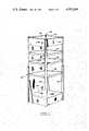
- FIG. 1is a perspective view of a preferred fourpost shelving unit in accordance with the invention
- FIG. 2is an exploded view of the base assembly of the unit
- FIG. 3is a fragmentary horizontal section taken through a corner of the base assembly and illustrating the means by which the base panels are secured together;
- FIG. 4is an exploded view showing details of the base panel assembly
- FIG. 5is a fragmentary elevational view of a side panel of the base, as viewed from the inside of the base assembly;
- FIG. 6is a perspective view of a two-section post, with a flexible, coilable trim sheet installed
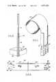
- FIG. 7is a perspective view illustrating the manner in which the flexible, coilable trim sheet is installed in a post
- FIG. 8is a side elevation of a shelf showing the front and rear shelf hooks
- FIG. 9is a horizontal section through a front corner of the shelving unit, illustrating the means by which the post and a shelf are tightly secured together and also illustrating the means by which the trim sheet is held in place;
- FIG. 10is a horizontal section through a rear corner of the shelving unit, illustrating the manner in which the rear corner of the shelf is secured to a post, and also illustrating the means by which clearance is provided for a panel at the rear of the shelf;
- FIG. 11is a vertical section taken through a front corner post on a plane parallel to the side of a shelf, and illustrating the camming action of the shelf hook;
- FIG. 12is a front elevation of a corner post in which the hook is shown in section, and in which the flexible trim sheet is removed, and illustrating the camming action of a slot in the post;
- FIG. 13is a three quarter view showing the inside of a post in accordance with the invention.
- FIG. 14is a horizontal section illustrating an alternative embodiment of the invention in which a single post of modified construction is used to support the adjacent front corners of two shelves arranged in side-by-side relationship.
- the shelving unitcomprises a base 20 providing a raised article-supporting surface, and four posts 22, 24, 26 and 28 secured to and extending upwardly from the respective four corners of the base. Shelves 28, 30 and 32 are supported one above another on the posts, the corners of the shelves being connected to the posts in the manner which will be described with reference to FIGS. 9-12.
- a conventional canopy assemblyis provided by panels 34, 36, 38 and 40. These panels can serve as signs if desired, and they may be provided at their lower edges with inwardly projecting flanges for supporting a translucent light diffuser.
- the base assemblyAs shown in FIG. 2, the base assembly, as supplied, consists of three unitary members.
- Member 42is a sheet metal member formed to provide a supporting surface 44, a front panel 46 and a rear panel 48.
- Rear panel 48has at its side edges, forwardly projecting flanges 50 and 52.
- Front panel 46has similar rearwardly projecting flanges, one of which is seen at 54. It should be noted that the lower edges of these flanges are tapered, as indicated at 56 and 58. Inwardly projecting flanges are also provided at the lower edges of panels 46 and 48, the flange on panel 48 being indicated at 60. The purpose of these latter flanges is merely to provide a large floor contact area.
- FIG. 2also shows two generally U-shaped assemblies 62 and 64.
- Assembly 62comprises a generally rectangular sheet metal panel 66 having upright sheet metal post elements 68 and 70 permanently secured to its opposite ends by spot welding.
- a generally triangular reinforcing bracket 72is connected between posts 70 and panel 62.
- Assembly 64similarly comprises post elements 76 and 78, which are welded to panel 74, and a reinforcing bracket 80.
- the upper and lower edges of panels 66 and 74have inwardly projecting flanges, the flanges at panel 74 being indicated respectively at 82 and 84.
- FIG. 3shows the manner in which the elements of FIG. 2 are secured together.
- Post element 68has a W-shaped web comprising vertically elongated rectangular sections 86, 88, 90 and 92. Sections 86 and 92 are perpendicular to each other, and sections 88 and 90 are respectively perpendicular to sections 86 and 92.
- the post sectionincludes section 94 projecting outwardly from web section 86, and a return flange 96 which is parallel to and spaced from web section 86.
- a similar outwardly projecting section 98is connected to web section 92, and a return flange 100, parallel to web section 92 is provided.
- Panel 66is permanently secured to web section 86 by spot welding, as shown.
- a flange 102projects inwardly from vertical edge 104 of panel 66 in parallel relationship to panel 46.
- An additional flange 106extends from and forms an acute angle with flange 102.
- edge 110 of flange 106extends into and contacts the corner formed by panel 46 and its flange 54, and holds flange 54 against web section 90 while also holding the face of panel 46 against web section 92.
- the flanges of panel 66are so related to the sections of post element 68 that the normal distance between end 110 of flange 106 and web section 90 is slightly less than the thickness of flange 54.
- the normal distance between end 110 of flange 106 and web section 92is preferably slightly less than the thickness of panel 46.
- flange 102in order to insert flange 54 into pocket 108, flange 102 must be sprung slightly so that end 110 of flange 106 is moved away from the corner formed by web sections 90 and 92.
- the spring characteristic of flange 102causes flange 106 to bear against the corner formed by panel 46 and flange 54 to secure the panels firmly together.
- the panelsare secured together at the corner by sliding flange 54 downwardly into the pocket formed by elements 90, 92, 102 and 106.
- the engagement of all four cornersis preferably carried out simultaneously. Even if the front and rear panels were separate and installed independently of each other, both vertical edges of each panel would be engaged simultaneously with both side panels.
- edge 110 of flange 106(FIG. 3) and the corner formed by web elements 90 and 92, it would be difficult to insert flange 54 into the pocket if no special precautions were taken. Insertion is also made difficult by the presence of the posts which are permanently secured to the side panels, as the posts prevent personnel from positioning their eyes in such a way as to align the flanges of the front and rear panels with the pockets formed on the side panels. The difficulty of alignment is compounded by the necessity for assembling multiple corners of the base system simultaneously.
- the upper edge 112 of flange 106(FIG. 5) is tapered in such a way as to guide flange 54 of the front panel into place by a camming action.
- edge 112serves to urge flange 54 toward web section 90.
- lower edge 58 of flange 54is also tapered.
- Lower edge 58cooperates with upper edge 114 of flange 102 to produce a further camming action urging panel 46 toward web section 92.
- U-shaped assemblies 62 and 64shown in FIG. 2, contribute to the strength of the shelving unit by reason of the fact that the posts are permanently secured to the side panels by welding. They also contribute to the simplicity of assembly, by reducing the number of separate parts. At the same time, as these preassembled U-shaped structures are not significantly larger than the other elements of the assembly, such as the shelves and the base, they do not materially increase the necessary size of the package in which the unit is shipped in a taken-down condition. Supplying the U-shaped elements in preassembled form in this manner, however, requires the use of two-section posts. As shown in FIG.
- post 24comprises a lower post element 68, and an upper post element 116, which has the same general configuration as post element 68, but which is of a smaller size so that it can telescope into the upper end of post element 68.
- the lower end of post element 116rests on struck-out tabs (not shown) formed in element 68.
- the trimWhen the post is fully assembled, trim is installed in the manner illustrated in FIG. 7.
- the trimconsists of a coilable flexible polyester sheet, treated in such a way that it has a memory, causing it to retain its coiled form, unless it is held in an uncoiled condition.
- a method of treatmentis described in Taber U.S. Pat. No. 3,426,115, dated Feb. 4, 1969, the disclosure of which patent is here incorporated by reference.
- the flexible coilable sheetcan be printed with patterns, product logos or the like in any desired color or combination of colors.
- the postsare discontinuous because of the fact that each consists of two interconnected post elements, the trim sheet in each post is continuous, and tends to obscure the discontinuity of the posts.
- FIG. 8shows the configuration of the front and rear hooks of shelf 28.
- the shelfis preferably formed from a light-gauge sheet metal element 122 which provides the main article-supporting surface, and heavy-gauge sheet metal side members, one of which is indicated at 124.
- One or more reinforcing channelsmay be provided underneath element 122, if desired.
- Retaining ridgesare formed in member 122 at 126 and 128, and similar retaining ridges are formed on the side members, the retaining ridge on side member 124 being indicated at 130.
- Side member 124has a horizontal flange 132, which extends substantially the full length of side member 124, and is located directly underneath sheet metal element 122.
- Element 122is secured to flange 132 by spot welding.
- the counterpart of side member 124 (not shown) on the opposite side of the shelfis similarly secured to the opposite edge of member 122.
- Front and rear skirt flangesare provided by extensions of element 122 at 134 and 136. These extensions project downwardly from retaining ridges 126 and 128 respectively.
- side element 124Adjacent the front edge of the shelf, side element 124 is formed into a hook 138, with a downwardly open notch 140. While the rear edge 142 of the notch is vertical, the front edge 144 of notch 140 is oblique, so that the upper end of edge 144 is closer to the rear of the shelf than is the lower edge. At the rear of element 124, a similar hook 146 is formed. Unlike hook 138, the front edge of which is adjacent front skirt flange 136, the rear edge of hook 146 projects beyond rear skirt flange 134. A notch is provided at 148, and the rear edge 150 of the notch is oblique so that its lower end is more rearward than its upper end. The front edge of the notch is also oblique so that the notch has a relatively wide opening.
- the V-shaped section of the web of lower post element 68is provided with a series of slots corresponding to slot 153.
- the upper post elementis provided with similar slots.
- the outer edges 154 and 156 of slot 153are aligned with the faces of web sections 92 and 86 respectively.
- hook 138extends through the slot having camming surface 160, and camming surface 160 cooperates with hook 138 in such a way that the hook is urged toward the right so that skirt flange 124 is pressed tightly against face 152 of web element 86.
- FIG. 12shows hook 138 in a partially engaged condition with the slot.
- the post and skirt flange 124are sufficiently resilient to allow the shelf to move downward with respect to the post beyond the position of the shelf at which skirt flange 124 first engages face 152 of web section 86.
- the resiliency needed in order to accomplish thiscan be resiliency in the skirt flanges of the shelf, or in the post, or both. Resiliency of the hook can also be used to accomplish this objective.
- the resiliency, and the relationship just describedis desirable in order to insure that the posts are held tightly against the shelves, even when the shelves are unloaded.
- the front skirt flange 136 of the shelfis held tightly against face 162 of web element 92. This tight relationship is accomplished by the engagement of oblique edge 144 of hook 138 with camming surface 160, as shown in FIG. 11, which shows the hook and slot in a partially engaged position.
- the resiliency of the posts and of front skirt flange 136 of the shelfallow the shelf to move downwardly slightly beyond the position of the shelf at which flange 136 first comes into engagement with face 162.
- the front flange 136 of the shelfis held tightly against face 162 of post web element 92, and side flange 152 is similarly held tightly against post web element 86 which is non-parallel to post element 92.
- the tight engagement of these elementsis accomplished by the dual-camming action of the hook and slot. Because of this tight engagement of the shelf with the post in two non-parallel planes, the post is unable to rotate about a vertical axis with respect to the shelf. So long as the other corners of the shelf are reasonably well supported against lateral movement by the other posts, the shelf serves as a lever arm locking the post of FIG. 9 against twisting.
- FIG. 10The connection between the shelf and rear post 22 is illustrated in FIG. 10.
- the camming action of oblique camming surface 164urges skirt 124 of the shelf tightly against face 166 of web element 168.
- a clearanceis provided at 172 between rear skirt flange 134 of the shelf and web element 170, and this clearance arises partly by reason of web element 174.
- a rear panel 176 of the shelving unitis received in the space between web element 170 and the shelf, while still further clearance is provided to allow easy entry of the front hooks of the shelf into the slots of the front posts.
- a pocket 178 formed by sections 174 and 180 of the postsreceives the end of hook 146, thereby preventing interference between the hook and trim sheet 182. This pocket also prevents the hook from projecting outwardly to a location where it could injure customers or cause damage to their clothing.
- the front post shown in FIG. 9has a similar pocket indicated at 184.
- Post 190comprises a web having a rear section 192, two parallel sections 194 and 196 extending forwardly from section 192, sections 198 and 200, extending perpendicularly and outwardly from sections 194 and 196 respectively, sections 202 and 204 extending forwardly from sections 198 and 200 respectively, and sections 206 and 208 extending outwardly from sections 202 and 204 respectively.
- Short forwardly extending sections 210 and 212, and return flanges 214 and 216provide grooves for receiving a trim sheet 218.
- Hooks 220 and 222 of the respective shelvesare received in slots in web elements 198 and 200. These slots have camming surfaces 224 and 226 which respectively urge the sides of the shelves tightly against web elements 194 and 196.
- the hooksare similar to hook 138 in FIG. 11, and have oblique surfaces corresponding to surface 144, which act together with the slots to urge the shelves forwardly against web elements 206 and 208. In this manner, the shelves themselves serve to reinforce the post.
- the postcan of course comprise multiple telescoping post elements.
Landscapes
- Assembled Shelves (AREA)
Abstract
Description
Claims (16)
Priority Applications (1)
| Application Number | Priority Date | Filing Date | Title |
|---|---|---|---|
| US06/116,585US4351244A (en) | 1980-01-29 | 1980-01-29 | Shelving system |
Applications Claiming Priority (1)
| Application Number | Priority Date | Filing Date | Title |
|---|---|---|---|
| US06/116,585US4351244A (en) | 1980-01-29 | 1980-01-29 | Shelving system |
Publications (1)
| Publication Number | Publication Date |
|---|---|
| US4351244Atrue US4351244A (en) | 1982-09-28 |
Family
ID=22368077
Family Applications (1)
| Application Number | Title | Priority Date | Filing Date |
|---|---|---|---|
| US06/116,585Expired - LifetimeUS4351244A (en) | 1980-01-29 | 1980-01-29 | Shelving system |
Country Status (1)
| Country | Link |
|---|---|
| US (1) | US4351244A (en) |
Cited By (34)
| Publication number | Priority date | Publication date | Assignee | Title |
|---|---|---|---|---|
| US4518279A (en)* | 1983-09-27 | 1985-05-21 | The Mead Corporation | Base element connection for sheet metal furniture |
| US4742782A (en)* | 1984-07-16 | 1988-05-10 | Fort Steuben Products Inc. | Sheet metal shelving assembly |
| US4821649A (en)* | 1986-09-23 | 1989-04-18 | Electrolux Constructor Aktiebolag | Sheet metal shelving |
| USD325137S (en) | 1988-07-06 | 1992-04-07 | Porter Michael J | Shelf unit |
| USD339941S (en) | 1991-04-22 | 1993-10-05 | The Mike Meehan Company | Advertising sleeve |
| US5415472A (en)* | 1992-02-10 | 1995-05-16 | Brise; Richard A. | Portable shelf |
| US5476315A (en)* | 1994-02-25 | 1995-12-19 | Ub Office Systems, Inc. | Corner assembly for cabinet side panel |
| USD368396S (en) | 1994-03-23 | 1996-04-02 | Paul Flum Ideas, Inc. | Product display unit with upper cooler shelf for merchandising cold products |
| USD368814S (en) | 1993-11-02 | 1996-04-16 | Superior Storage Systems, Inc. | Vertical storage unit |
| US5595312A (en)* | 1996-03-11 | 1997-01-21 | Dardashti; Shahriar | Easily assembled and adjustable storage and display tower assembly |
| USD387226S (en)* | 1996-02-20 | 1997-12-09 | Shahriar Dardashti | Storage and display stand |
| USD403175S (en) | 1996-08-06 | 1998-12-29 | Shahriar Dardashti | Storage and display stand |
| USD404936S (en)* | 1997-07-16 | 1999-02-02 | Shahriar Dardashti | Storage and display stand |
| USD406205S (en)* | 1997-07-16 | 1999-03-02 | Shahriar Dardashti | Storage and display stand |
| USD406204S (en)* | 1997-01-21 | 1999-03-02 | Shahriar Dardashti | Storage and display stand |
| USD407582S (en) | 1997-07-16 | 1999-04-06 | Shahriar Dardashti | Storage and display stand |
| US5908121A (en)* | 1996-03-11 | 1999-06-01 | Dardashti; Shahriar | Adjustable display assembly |
| USD415632S (en)* | 1996-10-16 | 1999-10-26 | Shahriar Dardashti | Storage and display stand |
| USD440078S1 (en) | 1998-09-16 | 2001-04-10 | Salvatore R. Carrabba | Storage cabinet |
| USD512585S1 (en)* | 2004-05-12 | 2005-12-13 | Thomasville Furniture Industries, Inc. | Etagere |
| US20060132008A1 (en)* | 2004-12-17 | 2006-06-22 | Benefiel David L | Stamped steel refrigerator shelf |
| US20080236071A1 (en)* | 2007-03-16 | 2008-10-02 | Surowiecki Matt F | Sheet metal corner studs |
| WO2011104623A1 (en)* | 2010-02-26 | 2011-09-01 | Pop Ontime Supply Services, S.A. De C.V. | Collapsible display structure |
| US20130126454A1 (en)* | 2011-11-17 | 2013-05-23 | Altria Group Distribution Company | Shelving system |
| US20130240461A1 (en)* | 2012-03-16 | 2013-09-19 | Ryan Scott Inc. | Product display tower |
| ITVR20130001A1 (en)* | 2013-01-04 | 2014-07-05 | Aicad Srl | SHELF OR SHELF EXHIBITOR WITH FAST MOUNTED STRUCTURE |
| US9301610B1 (en)* | 2015-02-09 | 2016-04-05 | Christopher H. Berry | Enclosed boltless shelving system |
| US20160352079A1 (en)* | 2014-02-05 | 2016-12-01 | Rittal Gmbh & Co. Kg | Frame section for a framework of a switchgear cabinet |
| USD833532S1 (en)* | 2016-11-09 | 2018-11-13 | Mark A. Hotchkiss | Three-dimensional alignment game board |
| US10368657B2 (en) | 2014-09-26 | 2019-08-06 | Eva Lilja | Channel glide assemblies |
| US11166547B2 (en)* | 2019-04-05 | 2021-11-09 | Harbor Industries, Inc. | Adjustable shelving assembly |
| US20230276941A1 (en)* | 2020-09-16 | 2023-09-07 | Perfect Site LLC | Utility rack |
| US12054340B2 (en)* | 2021-10-20 | 2024-08-06 | Conteyor International Nv | Flexible track-shelving system and a kit for converting a frame into a flexible track-shelving system |
| USD1095102S1 (en)* | 2024-08-08 | 2025-09-30 | Shenzhen Youbei Youpin Home Furnishings Co., Ltd. | Bookshelf |
Citations (31)
| Publication number | Priority date | Publication date | Assignee | Title |
|---|---|---|---|---|
| US854654A (en)* | 1905-09-22 | 1907-05-21 | Hubert Krantz | Construction for panel-boards and the like. |
| US860150A (en)* | 1906-10-03 | 1907-07-16 | Francis J Plym | Store-front and show-case construction. |
| US1129658A (en)* | 1914-06-03 | 1915-02-23 | John H Foy | Corner-form for concrete construction. |
| US1258043A (en)* | 1915-05-19 | 1918-03-05 | Francis J Plym | Store-front construction. |
| US1554011A (en)* | 1920-08-12 | 1925-09-15 | Edward G Lehman | Rack shelving |
| US2105784A (en)* | 1936-10-12 | 1938-01-18 | Paul C Hagberg | Window channel or the like |
| US2150795A (en)* | 1937-12-02 | 1939-03-14 | Louis I Beckwith | Joint arrangement |
| US2522097A (en)* | 1946-01-10 | 1950-09-12 | Cookson William | Joint between resilient sheet material parts |
| US2802487A (en)* | 1955-03-28 | 1957-08-13 | George F Breehl | Interlocking sheet metal joint |
| GB864123A (en)* | 1959-12-12 | 1961-03-29 | Nancy Hobson | Improvements in or relating to arrangements for use in supporting brackets or shelves |
| US2990067A (en)* | 1958-10-01 | 1961-06-27 | Harbor Metal Products Corp | Shelf structure |
| US3056507A (en)* | 1960-12-01 | 1962-10-02 | Dover Maid Ind Inc | Adjustable shelving |
| US3281102A (en)* | 1961-08-03 | 1966-10-25 | Nancy Hobson | Storage or display devices |
| US3306466A (en)* | 1965-08-09 | 1967-02-28 | American Metal Works Inc | Metal shelving |
| US3357457A (en)* | 1964-04-30 | 1967-12-12 | Hughes Aircraft Co | Collapsible tubular structure |
| US3426115A (en)* | 1965-07-23 | 1969-02-04 | Mead Corp | Method of making a self-coiling sheet |
| US3590759A (en)* | 1969-11-19 | 1971-07-06 | George S Hendrie Jr | Reinforcing strip for plastic articles and method and apparatus for making same |
| US3601256A (en)* | 1970-02-11 | 1971-08-24 | Mead Corp | Display stand |
| US3640389A (en)* | 1969-05-12 | 1972-02-08 | Chicago Display Co | Display stand and expendable shelf for use thereon |
| US3669036A (en)* | 1970-09-09 | 1972-06-13 | Howard J Marschak | Base for a display rack |
| US3698567A (en)* | 1971-05-27 | 1972-10-17 | Streater Ind Inc | Display stand |
| CA920987A (en)* | 1971-01-13 | 1973-02-13 | W. W. Behnke Klaus | Free-standing and self-supporting structure and shelves therefor |
| US3726413A (en)* | 1971-03-22 | 1973-04-10 | G Squires | Adjustable metal shelving |
| US3728834A (en)* | 1971-07-16 | 1973-04-24 | A Dean | Building corner assembly |
| US3810340A (en)* | 1970-10-09 | 1974-05-14 | Gypsum Co | Integral stud and bracket standard |
| US4064996A (en)* | 1975-12-17 | 1977-12-27 | Robert L. Shillum | Rack system |
| USD247184S (en) | 1976-04-29 | 1978-02-07 | The Mead Corporation | Shelf support post |
| US4135837A (en)* | 1978-01-19 | 1979-01-23 | The Mead Corporation | Shelving assembly |
| US4148263A (en)* | 1978-01-19 | 1979-04-10 | The Mead Corporation | Shelving assembly |
| US4201139A (en)* | 1979-01-15 | 1980-05-06 | The Mead Corporation | Shelving system |
| US4262809A (en)* | 1978-10-13 | 1981-04-21 | Interlake, Inc. | Slotted beam and loadlock therefor |
- 1980
- 1980-01-29USUS06/116,585patent/US4351244A/ennot_activeExpired - Lifetime
Patent Citations (31)
| Publication number | Priority date | Publication date | Assignee | Title |
|---|---|---|---|---|
| US854654A (en)* | 1905-09-22 | 1907-05-21 | Hubert Krantz | Construction for panel-boards and the like. |
| US860150A (en)* | 1906-10-03 | 1907-07-16 | Francis J Plym | Store-front and show-case construction. |
| US1129658A (en)* | 1914-06-03 | 1915-02-23 | John H Foy | Corner-form for concrete construction. |
| US1258043A (en)* | 1915-05-19 | 1918-03-05 | Francis J Plym | Store-front construction. |
| US1554011A (en)* | 1920-08-12 | 1925-09-15 | Edward G Lehman | Rack shelving |
| US2105784A (en)* | 1936-10-12 | 1938-01-18 | Paul C Hagberg | Window channel or the like |
| US2150795A (en)* | 1937-12-02 | 1939-03-14 | Louis I Beckwith | Joint arrangement |
| US2522097A (en)* | 1946-01-10 | 1950-09-12 | Cookson William | Joint between resilient sheet material parts |
| US2802487A (en)* | 1955-03-28 | 1957-08-13 | George F Breehl | Interlocking sheet metal joint |
| US2990067A (en)* | 1958-10-01 | 1961-06-27 | Harbor Metal Products Corp | Shelf structure |
| GB864123A (en)* | 1959-12-12 | 1961-03-29 | Nancy Hobson | Improvements in or relating to arrangements for use in supporting brackets or shelves |
| US3056507A (en)* | 1960-12-01 | 1962-10-02 | Dover Maid Ind Inc | Adjustable shelving |
| US3281102A (en)* | 1961-08-03 | 1966-10-25 | Nancy Hobson | Storage or display devices |
| US3357457A (en)* | 1964-04-30 | 1967-12-12 | Hughes Aircraft Co | Collapsible tubular structure |
| US3426115A (en)* | 1965-07-23 | 1969-02-04 | Mead Corp | Method of making a self-coiling sheet |
| US3306466A (en)* | 1965-08-09 | 1967-02-28 | American Metal Works Inc | Metal shelving |
| US3640389A (en)* | 1969-05-12 | 1972-02-08 | Chicago Display Co | Display stand and expendable shelf for use thereon |
| US3590759A (en)* | 1969-11-19 | 1971-07-06 | George S Hendrie Jr | Reinforcing strip for plastic articles and method and apparatus for making same |
| US3601256A (en)* | 1970-02-11 | 1971-08-24 | Mead Corp | Display stand |
| US3669036A (en)* | 1970-09-09 | 1972-06-13 | Howard J Marschak | Base for a display rack |
| US3810340A (en)* | 1970-10-09 | 1974-05-14 | Gypsum Co | Integral stud and bracket standard |
| CA920987A (en)* | 1971-01-13 | 1973-02-13 | W. W. Behnke Klaus | Free-standing and self-supporting structure and shelves therefor |
| US3726413A (en)* | 1971-03-22 | 1973-04-10 | G Squires | Adjustable metal shelving |
| US3698567A (en)* | 1971-05-27 | 1972-10-17 | Streater Ind Inc | Display stand |
| US3728834A (en)* | 1971-07-16 | 1973-04-24 | A Dean | Building corner assembly |
| US4064996A (en)* | 1975-12-17 | 1977-12-27 | Robert L. Shillum | Rack system |
| USD247184S (en) | 1976-04-29 | 1978-02-07 | The Mead Corporation | Shelf support post |
| US4135837A (en)* | 1978-01-19 | 1979-01-23 | The Mead Corporation | Shelving assembly |
| US4148263A (en)* | 1978-01-19 | 1979-04-10 | The Mead Corporation | Shelving assembly |
| US4262809A (en)* | 1978-10-13 | 1981-04-21 | Interlake, Inc. | Slotted beam and loadlock therefor |
| US4201139A (en)* | 1979-01-15 | 1980-05-06 | The Mead Corporation | Shelving system |
Cited By (43)
| Publication number | Priority date | Publication date | Assignee | Title |
|---|---|---|---|---|
| US4518279A (en)* | 1983-09-27 | 1985-05-21 | The Mead Corporation | Base element connection for sheet metal furniture |
| US4742782A (en)* | 1984-07-16 | 1988-05-10 | Fort Steuben Products Inc. | Sheet metal shelving assembly |
| US4821649A (en)* | 1986-09-23 | 1989-04-18 | Electrolux Constructor Aktiebolag | Sheet metal shelving |
| USD325137S (en) | 1988-07-06 | 1992-04-07 | Porter Michael J | Shelf unit |
| USD339941S (en) | 1991-04-22 | 1993-10-05 | The Mike Meehan Company | Advertising sleeve |
| US5415472A (en)* | 1992-02-10 | 1995-05-16 | Brise; Richard A. | Portable shelf |
| USD368814S (en) | 1993-11-02 | 1996-04-16 | Superior Storage Systems, Inc. | Vertical storage unit |
| US5476315A (en)* | 1994-02-25 | 1995-12-19 | Ub Office Systems, Inc. | Corner assembly for cabinet side panel |
| USD368396S (en) | 1994-03-23 | 1996-04-02 | Paul Flum Ideas, Inc. | Product display unit with upper cooler shelf for merchandising cold products |
| USD387226S (en)* | 1996-02-20 | 1997-12-09 | Shahriar Dardashti | Storage and display stand |
| US5595312A (en)* | 1996-03-11 | 1997-01-21 | Dardashti; Shahriar | Easily assembled and adjustable storage and display tower assembly |
| US5875895A (en)* | 1996-03-11 | 1999-03-02 | Dardashti; Shahriar | Display and storage assembly kit |
| US5908121A (en)* | 1996-03-11 | 1999-06-01 | Dardashti; Shahriar | Adjustable display assembly |
| USD403175S (en) | 1996-08-06 | 1998-12-29 | Shahriar Dardashti | Storage and display stand |
| USD415632S (en)* | 1996-10-16 | 1999-10-26 | Shahriar Dardashti | Storage and display stand |
| USD406204S (en)* | 1997-01-21 | 1999-03-02 | Shahriar Dardashti | Storage and display stand |
| USD404936S (en)* | 1997-07-16 | 1999-02-02 | Shahriar Dardashti | Storage and display stand |
| USD406205S (en)* | 1997-07-16 | 1999-03-02 | Shahriar Dardashti | Storage and display stand |
| USD407582S (en) | 1997-07-16 | 1999-04-06 | Shahriar Dardashti | Storage and display stand |
| USD440078S1 (en) | 1998-09-16 | 2001-04-10 | Salvatore R. Carrabba | Storage cabinet |
| USD512585S1 (en)* | 2004-05-12 | 2005-12-13 | Thomasville Furniture Industries, Inc. | Etagere |
| US20060132008A1 (en)* | 2004-12-17 | 2006-06-22 | Benefiel David L | Stamped steel refrigerator shelf |
| US20080236071A1 (en)* | 2007-03-16 | 2008-10-02 | Surowiecki Matt F | Sheet metal corner studs |
| US7703247B2 (en)* | 2007-03-16 | 2010-04-27 | Surowiecki Matt F | Sheet metal corner studs |
| WO2011104623A1 (en)* | 2010-02-26 | 2011-09-01 | Pop Ontime Supply Services, S.A. De C.V. | Collapsible display structure |
| US9339108B2 (en) | 2011-11-17 | 2016-05-17 | Altria Group Distribution Company | Shelving system having a shelf with biasing elements to resist inadvertent or accidental detachment from a support rail |
| US20130126454A1 (en)* | 2011-11-17 | 2013-05-23 | Altria Group Distribution Company | Shelving system |
| US9016214B2 (en)* | 2011-11-17 | 2015-04-28 | Altria Group Distribution Company | Shelving system having a shelf with biasing elements to resist inadvertent or accidental detachment from a support rail |
| US20130240461A1 (en)* | 2012-03-16 | 2013-09-19 | Ryan Scott Inc. | Product display tower |
| ITVR20130001A1 (en)* | 2013-01-04 | 2014-07-05 | Aicad Srl | SHELF OR SHELF EXHIBITOR WITH FAST MOUNTED STRUCTURE |
| US20160352079A1 (en)* | 2014-02-05 | 2016-12-01 | Rittal Gmbh & Co. Kg | Frame section for a framework of a switchgear cabinet |
| US9966738B2 (en)* | 2014-02-05 | 2018-05-08 | Rittal Gmbh & Co. Kg | Frame section for a framework of a switchgear cabinet |
| US10368657B2 (en) | 2014-09-26 | 2019-08-06 | Eva Lilja | Channel glide assemblies |
| US10455953B2 (en) | 2014-09-26 | 2019-10-29 | Monster Energy Company | Channel glide assemblies |
| US10806275B2 (en) | 2014-09-26 | 2020-10-20 | Eva Lilja | Channel glide assemblies |
| US11439252B2 (en) | 2014-09-26 | 2022-09-13 | Eva Lilja | Channel glide assemblies |
| US9301610B1 (en)* | 2015-02-09 | 2016-04-05 | Christopher H. Berry | Enclosed boltless shelving system |
| USD833532S1 (en)* | 2016-11-09 | 2018-11-13 | Mark A. Hotchkiss | Three-dimensional alignment game board |
| US11166547B2 (en)* | 2019-04-05 | 2021-11-09 | Harbor Industries, Inc. | Adjustable shelving assembly |
| US20230276941A1 (en)* | 2020-09-16 | 2023-09-07 | Perfect Site LLC | Utility rack |
| US12144421B2 (en)* | 2020-09-16 | 2024-11-19 | Perfect Site LLC | Utility rack |
| US12054340B2 (en)* | 2021-10-20 | 2024-08-06 | Conteyor International Nv | Flexible track-shelving system and a kit for converting a frame into a flexible track-shelving system |
| USD1095102S1 (en)* | 2024-08-08 | 2025-09-30 | Shenzhen Youbei Youpin Home Furnishings Co., Ltd. | Bookshelf |
Similar Documents
| Publication | Publication Date | Title |
|---|---|---|
| US4351244A (en) | Shelving system | |
| US5509541A (en) | Bracket construction | |
| US4850285A (en) | Shelving system | |
| CA1198098A (en) | Merchandising display system and components therefor | |
| EP0752823B1 (en) | Display fixture system | |
| US5370249A (en) | Display fixture assembly | |
| US4444322A (en) | Display rack | |
| US6193085B1 (en) | Dispensing rack | |
| US4821649A (en) | Sheet metal shelving | |
| US6173846B1 (en) | Safety stop for pallet rack | |
| US6062402A (en) | Modular merchandising display rack | |
| US2766958A (en) | Display and merchandise support | |
| US3883004A (en) | Cantilever movable panel display rack | |
| US5437116A (en) | Modular sign system | |
| US10945539B2 (en) | Merchandise display fixture | |
| US3088598A (en) | Merchandise display rack | |
| US20010022043A1 (en) | Shelf-mount sign system | |
| JPS63111817A (en) | Article support and display apparatus | |
| US5040688A (en) | Foldable display | |
| US6799689B2 (en) | Shelving display rack | |
| US5718343A (en) | Suspended displays | |
| US4332204A (en) | Merchandising display stand | |
| US5325973A (en) | Bicycle support rack | |
| US3770135A (en) | Shelving construction | |
| US3973678A (en) | Display brackets |
Legal Events
| Date | Code | Title | Description |
|---|---|---|---|
| AS | Assignment | Owner name:MEAD CORPORATION THE, 950 WEST MARIETTA ST., ATLAN Free format text:ASSIGNMENT OF ASSIGNORS INTEREST.;ASSIGNOR:HOPEMAN BROTHERS, INC.;REEL/FRAME:003851/0132 Effective date:19810421 Owner name:HOPEMAN BROTHERS, INC., 435 ESSEX AVE., WAYNESBORO Free format text:ASSIGNMENT OF ASSIGNORS INTEREST.;ASSIGNOR:SUTTLES JAMES M.;REEL/FRAME:003851/0129 Effective date:19810126 | |
| STCF | Information on status: patent grant | Free format text:PATENTED CASE | |
| AS | Assignment | Owner name:SOUTHTRUST BANK, ALABAMA Free format text:SECURITY AGREEMENT;ASSIGNOR:DISPLAY INDUSTRIES, LLC;REEL/FRAME:013203/0845 Effective date:20020408 | |
| AS | Assignment | Owner name:FCC, LLC D/B/A FIRST CAPITAL, GEORGIA Free format text:SECURITY AGREEMENT;ASSIGNOR:DISPLAY INDUSTRIES, LLC;REEL/FRAME:028467/0968 Effective date:20120625 | |
| AS | Assignment | Owner name:BIG SHOULDERS CAPITAL, LLC, ILLINOIS Free format text:ASSIGNMENT AND ASSUMPTION OF A SECURITY INTEREST;ASSIGNOR:FCC, LLC D/B/A FIRST CAPITAL;REEL/FRAME:036537/0820 Effective date:20150811 |