US4350016A - Device and process for effecting refrigeration - Google Patents
Device and process for effecting refrigerationDownload PDFInfo
- Publication number
- US4350016A US4350016AUS06/236,523US23652381AUS4350016AUS 4350016 AUS4350016 AUS 4350016AUS 23652381 AUS23652381 AUS 23652381AUS 4350016 AUS4350016 AUS 4350016A
- Authority
- US
- United States
- Prior art keywords
- face
- gaseous medium
- ambient
- liquid
- heat
- Prior art date
- Legal status (The legal status is an assumption and is not a legal conclusion. Google has not performed a legal analysis and makes no representation as to the accuracy of the status listed.)
- Expired - Fee Related
Links
- 238000000034methodMethods0.000titleclaimsabstractdescription11
- 230000008569processEffects0.000titleclaimsabstractdescription11
- 238000005057refrigerationMethods0.000titleclaimsabstractdescription6
- 239000007788liquidSubstances0.000claimsabstractdescription36
- 229910052751metalInorganic materials0.000claimsabstractdescription21
- 239000002184metalSubstances0.000claimsabstractdescription21
- 238000009834vaporizationMethods0.000claimsabstractdescription14
- 230000008016vaporizationEffects0.000claimsabstractdescription14
- XLYOFNOQVPJJNP-UHFFFAOYSA-NwaterSubstancesOXLYOFNOQVPJJNP-UHFFFAOYSA-N0.000claimsabstractdescription12
- 238000001816coolingMethods0.000claimsabstractdescription11
- 239000007921spraySubstances0.000claimsdescription8
- 230000006872improvementEffects0.000claimsdescription5
- 239000000463materialSubstances0.000claimsdescription3
- 230000002745absorbentEffects0.000claims1
- 239000002250absorbentSubstances0.000claims1
- 230000004048modificationEffects0.000description5
- 238000012986modificationMethods0.000description5
- 230000006835compressionEffects0.000description3
- 238000007906compressionMethods0.000description3
- 230000009471actionEffects0.000description2
- 239000004020conductorSubstances0.000description2
- 238000010276constructionMethods0.000description2
- 229910052782aluminiumInorganic materials0.000description1
- XAGFODPZIPBFFR-UHFFFAOYSA-NaluminiumChemical compound[Al]XAGFODPZIPBFFR-UHFFFAOYSA-N0.000description1
- 239000012080ambient airSubstances0.000description1
- 238000009835boilingMethods0.000description1
- 230000002301combined effectEffects0.000description1
- 238000007710freezingMethods0.000description1
- 230000008014freezingEffects0.000description1
- 230000000717retained effectEffects0.000description1
- 239000007787solidSubstances0.000description1
Images
Classifications
- F—MECHANICAL ENGINEERING; LIGHTING; HEATING; WEAPONS; BLASTING
- F28—HEAT EXCHANGE IN GENERAL
- F28D—HEAT-EXCHANGE APPARATUS, NOT PROVIDED FOR IN ANOTHER SUBCLASS, IN WHICH THE HEAT-EXCHANGE MEDIA DO NOT COME INTO DIRECT CONTACT
- F28D15/00—Heat-exchange apparatus with the intermediate heat-transfer medium in closed tubes passing into or through the conduit walls ; Heat-exchange apparatus employing intermediate heat-transfer medium or bodies
- F28D15/02—Heat-exchange apparatus with the intermediate heat-transfer medium in closed tubes passing into or through the conduit walls ; Heat-exchange apparatus employing intermediate heat-transfer medium or bodies in which the medium condenses and evaporates, e.g. heat pipes
- F28D15/04—Heat-exchange apparatus with the intermediate heat-transfer medium in closed tubes passing into or through the conduit walls ; Heat-exchange apparatus employing intermediate heat-transfer medium or bodies in which the medium condenses and evaporates, e.g. heat pipes with tubes having a capillary structure
- F—MECHANICAL ENGINEERING; LIGHTING; HEATING; WEAPONS; BLASTING
- F25—REFRIGERATION OR COOLING; COMBINED HEATING AND REFRIGERATION SYSTEMS; HEAT PUMP SYSTEMS; MANUFACTURE OR STORAGE OF ICE; LIQUEFACTION SOLIDIFICATION OF GASES
- F25B—REFRIGERATION MACHINES, PLANTS OR SYSTEMS; COMBINED HEATING AND REFRIGERATION SYSTEMS; HEAT PUMP SYSTEMS
- F25B21/00—Machines, plants or systems, using electric or magnetic effects
- F25B21/02—Machines, plants or systems, using electric or magnetic effects using Peltier effect; using Nernst-Ettinghausen effect
- F—MECHANICAL ENGINEERING; LIGHTING; HEATING; WEAPONS; BLASTING
- F25—REFRIGERATION OR COOLING; COMBINED HEATING AND REFRIGERATION SYSTEMS; HEAT PUMP SYSTEMS; MANUFACTURE OR STORAGE OF ICE; LIQUEFACTION SOLIDIFICATION OF GASES
- F25B—REFRIGERATION MACHINES, PLANTS OR SYSTEMS; COMBINED HEATING AND REFRIGERATION SYSTEMS; HEAT PUMP SYSTEMS
- F25B2321/00—Details of machines, plants or systems, using electric or magnetic effects
- F25B2321/02—Details of machines, plants or systems, using electric or magnetic effects using Peltier effects; using Nernst-Ettinghausen effects
- F25B2321/023—Mounting details thereof
Definitions
- thermoelectric elementhaving a hot face and a cold face activated by imposing a direct current potential across the faces thereof, wherein the hot face is cooled by conducting heat into an extraneous medium.
- the inventionis directed to a device and process of the class described wherein the heat is conducted by means of a thermal sink, one face of which is in direct heat transfer with the hot face and the other face of which is in direct heat transfer with an enveloping ambient, gaseous medium and in which a vaporizable liquid is applied to the other face concomitantly with it being exposed to the ambient, gaseous medium, whereby cooling is effected, both by direct heat transfer into said gaseous medium and by vaporization of said liquid.
- the vaporizable liquidis absorbed into a capillary metal sponge, one part of which is exposed to the ambient, gaseous medium and another part of which is in direct heat transfer contact with the other face of the thermal sink.
- the metal spongeboth to a vaporizable liquid and to the ambient, gaseous medium
- the liquidis absorbed on the capillary surfaces of the sponge and evaporated therefrom into the ambient, gaseous medium, whereby cooling by the combined effect of the heat of vaporization of the liquid and by heat transfer into the gaseous medium is obtained.
- FIG. 1is a cross-sectional view in side elevation of one form of the invention
- FIG. 2is a cross-sectional view in side elevation of another form of the invention.
- FIG. 3is a cross-sectional view in side elevation of still another form of the invention.
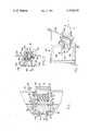
- FIG. 1is a partial view of a wall of a device in which heat is to be transferred from area A to an enveloping ambient, gaseous medium B.
- the motivating force for the heat transferis a thermoelectric element 10 which is operative when a direct potential is impressed across faces 12 and 14 thereof, when the polarity is right, to cause the face 12 to become cold and the face 14 to become hot.
- the cold face 12is in direct heat-transfer contact with a thermal sink 16 composed of a solid body 18 of suitable heat-conducting material, for example, aluminum, and a liner 20 of like material fastened thereto by bolts 22, or the like.
- the hot face 14is in direct heat-transfer contact with an external sink 24 of like heat-conducting material.
- the external thermal sink 24comprises a head 26 and a threaded portion 28 so that it can be inserted through a hole in wall 30 and fastened thereto by nut 32. Between the nut 32 and the wall 30 is interposed a washer 34 having threaded bores therein to receive the threaded ends 37 of bolts 38 which extend through wings 40 on the internal thermal sink 18 so that the assembly can be bolted together to place the thermoelectric element 10 in compression between the internal thermal sink 18 and the external sink 34.
- the head 26has fused thereto, or otherwise in direct heat-contact therewith, a porous metal sponge 36.
- a spray head 39Fastened to the wall 30 is a spray head 39 arranged to spray water or like vaporizable liquid onto the metal sponge 36. It will, of course, be understood that the spray head 39 can be arranged to spray the liquid on the face of the metal sponge 36, or to spray it on the top thereof, as shown. Also, it is to be understood tha the spray head 39 can be arranged to drip water onto the metal sponge 36.
- the essential featureis that a vaporizable liquid is applied to the metal sponge so that it can be absorbed into the capillaries thereof concomitantly with the metal sponge being exposed to the ambient air or like gaseous medium B.
- the heat transferred by the thermoelectric element into the external thermal sinkcauses the absorbed liquid to be vaporized into the ambient, gaseous medium so that cooling is effected, both by direct heat transfer into the ambient, gaseous medium and by transfer into heat of vaporization of the liquid.
- FIG. 2illustrates a modification in which the external thermal sink 24 comprises a heat pipe 42 comprisng a cavity in the heat sink 24 lined with a capillary sponge 44 and partially filled with a vaporizable liquid having a boiling point such that it is condensed at the outer end of the heat pipe, conducted to the inner end by capillary action, and vaporized there to complete a cycle in which heat is transferred from one end to the other, at least in part by the heat of vaporization of liquid in the heat pipe.
- the external thermal sink 24comprises a heat pipe 42 comprisng a cavity in the heat sink 24 lined with a capillary sponge 44 and partially filled with a vaporizable liquid having a boiling point such that it is condensed at the outer end of the heat pipe, conducted to the inner end by capillary action, and vaporized there to complete a cycle in which heat is transferred from one end to the other, at least in part by the heat of vaporization of liquid in the heat pipe.
- the nut 32ahas wings 46 into which are threaded bolts 38a. These bolts pass through the liner 20a and wings 40a in the internal thermal sink 18a. Thus, by tightening up the bolts 38a, the thermoelectric element 10a is placed under compression between the internal thermal sink 18a and the external thermal sink 24a, and the whole unit is thus secured to the wall 30a.
- the internal thermal sink 18ais constructed as a channel-shaped member in which the cavity 48 can be adjusted in size to determine the heat sink capability of the heat sink 18a.
- a trough 50for holding an intact body of water or liquid in contact with the bottom portion of the metal capillary sponge 36a.
- wateris drawn up from the trough 50 into the metal sponge 36a by capillary action where it is evaporated by the heat transferred from A and thus dissipated into the ambient atmosphere B.
- FIG. 3illustrates a modification of the invention in which the device is designed for cooling a refrigerator in a boat, or like watercraft.
- the refrigerator 52comprises a freezing compartment 54 and a cooling compartment 56.
- the walls 58are formed as integral extensions of the internal thermal sink 18b which is fastened to the external thermal sink 24b by bolts 38b which place the thermoelectric element 10b in compression between the internal thermal sink 18b and the external thermal sink 24b.
- the external thermal sink 24bis fastened to the hull 60 of a watercraft by means of screws 62.
- Inset in the hull 60is a capillary metal sponge 36b having its inner face 64 in direct heat-transfer contact with the external thermal sink 24b and its outer face 66 exposed in part to the ambient atmosphere B and the ambient water C.
- edges 68 of the sponge 36bare beveled, as are the corresponding edges of the aperture in the hull 66, so that the sponge 36b is retained when the outer face of the external thermal sink is drawn up tight against the inner face 64 of the sponge 36b by the screws 62. In this construction, it is not necessary to have the sponge 36b fused or otherwise secured to the external thermal sink 24b, although it is to be understood that this can be done, if desired.
- the metal sponge 36blocated at the water level, as shown in FIG. 3 because, if it is located substantially above the water level, it still will be wetted by the water due to the lapping of the waves against the hull, both when riding at anchor and when traveling.
- the capillary metal spongecan be omitted and the water sprayed or splashed directly on the exposed surface of the external thermal sink. A marked improvement in the efficiency of the device is obtained, however, by use of the capillary metal sponge, as illustrated and described.
Landscapes
- Engineering & Computer Science (AREA)
- Physics & Mathematics (AREA)
- Mechanical Engineering (AREA)
- Thermal Sciences (AREA)
- General Engineering & Computer Science (AREA)
- Life Sciences & Earth Sciences (AREA)
- Sustainable Development (AREA)
Abstract
Description
Claims (10)
Priority Applications (1)
| Application Number | Priority Date | Filing Date | Title |
|---|---|---|---|
| US06/236,523US4350016A (en) | 1981-02-20 | 1981-02-20 | Device and process for effecting refrigeration |
Applications Claiming Priority (1)
| Application Number | Priority Date | Filing Date | Title |
|---|---|---|---|
| US06/236,523US4350016A (en) | 1981-02-20 | 1981-02-20 | Device and process for effecting refrigeration |
Publications (1)
| Publication Number | Publication Date |
|---|---|
| US4350016Atrue US4350016A (en) | 1982-09-21 |
Family
ID=22889875
Family Applications (1)
| Application Number | Title | Priority Date | Filing Date |
|---|---|---|---|
| US06/236,523Expired - Fee RelatedUS4350016A (en) | 1981-02-20 | 1981-02-20 | Device and process for effecting refrigeration |
Country Status (1)
| Country | Link |
|---|---|
| US (1) | US4350016A (en) |
Cited By (3)
| Publication number | Priority date | Publication date | Assignee | Title |
|---|---|---|---|---|
| RU2140365C1 (en)* | 1997-06-27 | 1999-10-27 | Миасский машиностроительный завод | Device for cooling and heating air in closed space |
| US6034875A (en)* | 1998-06-17 | 2000-03-07 | International Business Machines Corporation | Cooling structure for electronic components |
| WO2006010539A3 (en)* | 2004-07-23 | 2006-04-27 | Bsh Bosch Siemens Hausgeraete | Refrigerating device and cooling device and peltier-cooling device therefor |
Citations (10)
| Publication number | Priority date | Publication date | Assignee | Title |
|---|---|---|---|---|
| US2886618A (en)* | 1953-11-20 | 1959-05-12 | Gen Electric Co Ltd | Thermoelectric devices |
| US2931188A (en)* | 1958-05-02 | 1960-04-05 | Whirlpool Co | Fluid cooling apparatus |
| US3008299A (en)* | 1959-04-09 | 1961-11-14 | Carrier Corp | Thermoelectric water cooler |
| US3008300A (en)* | 1959-04-09 | 1961-11-14 | Carrier Corp | Thermoelectric apparatus for heating or cooling of fluids |
| US3154926A (en)* | 1962-09-25 | 1964-11-03 | Max L Hirschhorn | Cooling blanket |
| US3212274A (en)* | 1964-07-28 | 1965-10-19 | Eidus William | Thermoelectric condenser |
| US3216205A (en)* | 1963-01-15 | 1965-11-09 | Tecumseh Products Co | Low loss thermoelectric heat exchanger |
| US3740959A (en)* | 1971-09-16 | 1973-06-26 | F Foss | Humidifier dehumidifier device |
| US3874183A (en)* | 1974-02-21 | 1975-04-01 | Hughes D Burton | Cooling device for fluid of a motor vehicle transmission |
| US4055053A (en)* | 1975-12-08 | 1977-10-25 | Elfving Thore M | Thermoelectric water cooler or ice freezer |
- 1981
- 1981-02-20USUS06/236,523patent/US4350016A/ennot_activeExpired - Fee Related
Patent Citations (10)
| Publication number | Priority date | Publication date | Assignee | Title |
|---|---|---|---|---|
| US2886618A (en)* | 1953-11-20 | 1959-05-12 | Gen Electric Co Ltd | Thermoelectric devices |
| US2931188A (en)* | 1958-05-02 | 1960-04-05 | Whirlpool Co | Fluid cooling apparatus |
| US3008299A (en)* | 1959-04-09 | 1961-11-14 | Carrier Corp | Thermoelectric water cooler |
| US3008300A (en)* | 1959-04-09 | 1961-11-14 | Carrier Corp | Thermoelectric apparatus for heating or cooling of fluids |
| US3154926A (en)* | 1962-09-25 | 1964-11-03 | Max L Hirschhorn | Cooling blanket |
| US3216205A (en)* | 1963-01-15 | 1965-11-09 | Tecumseh Products Co | Low loss thermoelectric heat exchanger |
| US3212274A (en)* | 1964-07-28 | 1965-10-19 | Eidus William | Thermoelectric condenser |
| US3740959A (en)* | 1971-09-16 | 1973-06-26 | F Foss | Humidifier dehumidifier device |
| US3874183A (en)* | 1974-02-21 | 1975-04-01 | Hughes D Burton | Cooling device for fluid of a motor vehicle transmission |
| US4055053A (en)* | 1975-12-08 | 1977-10-25 | Elfving Thore M | Thermoelectric water cooler or ice freezer |
Cited By (4)
| Publication number | Priority date | Publication date | Assignee | Title |
|---|---|---|---|---|
| RU2140365C1 (en)* | 1997-06-27 | 1999-10-27 | Миасский машиностроительный завод | Device for cooling and heating air in closed space |
| US6034875A (en)* | 1998-06-17 | 2000-03-07 | International Business Machines Corporation | Cooling structure for electronic components |
| US6453537B1 (en) | 1998-06-17 | 2002-09-24 | International Business Machines Corporation | Cooling method for electronic components |
| WO2006010539A3 (en)* | 2004-07-23 | 2006-04-27 | Bsh Bosch Siemens Hausgeraete | Refrigerating device and cooling device and peltier-cooling device therefor |
Similar Documents
| Publication | Publication Date | Title |
|---|---|---|
| FR2444894A1 (en) | THERMALLY INSULATED HEAT ACCUMULATOR | |
| US4355518A (en) | Refrigerator-vehicle combination method | |
| US3952797A (en) | Semi conductor cooling system | |
| US4350016A (en) | Device and process for effecting refrigeration | |
| JPH04227485A (en) | Evaporating heat exchanger | |
| JPS57157841A (en) | Disc rotor sealed with coolant | |
| JP2007120933A (en) | Heat exchanger | |
| JPS6136348Y2 (en) | ||
| US3989095A (en) | Semi conductor cooling system | |
| JPH0136067Y2 (en) | ||
| JPS5818517U (en) | Electronic cooling device | |
| SU1409826A1 (en) | Thermoelectric refrigerator | |
| JPS58168893A (en) | Heat accumulator | |
| JPS64543Y2 (en) | ||
| JPS6252770U (en) | ||
| JPS63238370A (en) | Air cooler | |
| JPS6428492A (en) | Heat exchanger | |
| JPS63265752A (en) | Fluid heating device | |
| JPH0942815A (en) | Instant cooling type beverage supply device | |
| JPS6120778Y2 (en) | ||
| US3167932A (en) | Evaporator for a liquid freezing apparatus | |
| GB1305299A (en) | ||
| JPS6115424Y2 (en) | ||
| SU532505A2 (en) | Device for fastening metal and non-metal parts | |
| JPS5849018Y2 (en) | Cooling system |
Legal Events
| Date | Code | Title | Description |
|---|---|---|---|
| AS | Assignment | Owner name:BIPOL LTD. 57,IBM GIVROL ST.TEL-AVIV,ISRAEL A CORP Free format text:ASSIGNMENT OF ASSIGNORS INTEREST.;ASSIGNOR:BEITNER SHLOMO;REEL/FRAME:003863/0301 Effective date:19810216 | |
| CC | Certificate of correction | ||
| AS | Assignment | Owner name:BASIC MINERALS & CHEMICALS, INC. Free format text:SETTLEMENT AGREEMENT AND RELEASE DATED MAY 10, 1983;ASSIGNORS:BASIC MINERALS & CHEMICALS, INC.;BILAN, INC.;LANDO,HERMAN B.;AND OTHERS;REEL/FRAME:004187/0354 Effective date:19830526 Owner name:BILAN, INC. Free format text:SETTLEMENT AGREEMENT AND RELEASE DATED MAY 10, 1983;ASSIGNORS:BASIC MINERALS & CHEMICALS, INC.;BILAN, INC.;LANDO,HERMAN B.;AND OTHERS;REEL/FRAME:004187/0354 Effective date:19830526 Owner name:LANDO, HERMAN B. Free format text:SETTLEMENT AGREEMENT AND RELEASE DATED MAY 10, 1983;ASSIGNORS:BASIC MINERALS & CHEMICALS, INC.;BILAN, INC.;LANDO,HERMAN B.;AND OTHERS;REEL/FRAME:004187/0354 Effective date:19830526 Owner name:BIPOL LTD. Free format text:SETTLEMENT AGREEMENT AND RELEASE DATED MAY 10, 1983;ASSIGNORS:BASIC MINERALS & CHEMICALS, INC.;BILAN, INC.;LANDO,HERMAN B.;AND OTHERS;REEL/FRAME:004187/0354 Effective date:19830526 Owner name:BEITNER, SHLOMO Free format text:SETTLEMENT AGREEMENT AND RELEASE DATED MAY 10, 1983;ASSIGNORS:BASIC MINERALS & CHEMICALS, INC.;BILAN, INC.;LANDO,HERMAN B.;AND OTHERS;REEL/FRAME:004187/0354 Effective date:19830526 Owner name:THERMOPOL, INC. Free format text:SETTLEMENT AGREEMENT AND RELEASE DATED MAY 10, 1983;ASSIGNORS:BASIC MINERALS & CHEMICALS, INC.;BILAN, INC.;LANDO,HERMAN B.;AND OTHERS;REEL/FRAME:004187/0354 Effective date:19830526 Owner name:BIPOL LTD., STATELESS Free format text:SETTLEMENT AGREEMENT AND RELEASE DATED MAY 10, 1983;ASSIGNORS:BASIC MINERALS & CHEMICALS, INC.;BILAN, INC.;LANDO,HERMAN B.;AND OTHERS;REEL/FRAME:004187/0354 Effective date:19830526 Owner name:BEITNER, SHLOMO, STATELESS Free format text:SETTLEMENT AGREEMENT AND RELEASE DATED MAY 10, 1983;ASSIGNORS:BASIC MINERALS & CHEMICALS, INC.;BILAN, INC.;LANDO,HERMAN B.;AND OTHERS;REEL/FRAME:004187/0354 Effective date:19830526 | |
| FEPP | Fee payment procedure | Free format text:MAINTENANCE FEE REMINDER MAILED (ORIGINAL EVENT CODE: REM.); ENTITY STATUS OF PATENT OWNER: LARGE ENTITY | |
| LAPS | Lapse for failure to pay maintenance fees | ||
| STCH | Information on status: patent discontinuation | Free format text:PATENT EXPIRED DUE TO NONPAYMENT OF MAINTENANCE FEES UNDER 37 CFR 1.362 | |
| FP | Lapsed due to failure to pay maintenance fee | Effective date:19860921 |