US4344597A - Vehicle seat with fore-and-aft shock isolation - Google Patents
Vehicle seat with fore-and-aft shock isolationDownload PDFInfo
- Publication number
- US4344597A US4344597AUS06/142,339US14233980AUS4344597AUS 4344597 AUS4344597 AUS 4344597AUS 14233980 AUS14233980 AUS 14233980AUS 4344597 AUS4344597 AUS 4344597A
- Authority
- US
- United States
- Prior art keywords
- fore
- seat part
- latching member
- aft
- seat
- Prior art date
- Legal status (The legal status is an assumption and is not a legal conclusion. Google has not performed a legal analysis and makes no representation as to the accuracy of the status listed.)
- Expired - Lifetime
Links
- 230000035939shockEffects0.000titleabstractdescription15
- 238000002955isolationMethods0.000titledescription16
- 239000000725suspensionSubstances0.000claimsabstractdescription35
- 230000003068static effectEffects0.000description4
- 230000001133accelerationEffects0.000description1
- 230000006835compressionEffects0.000description1
- 238000007906compressionMethods0.000description1
- 125000006850spacer groupChemical group0.000description1
Images


Classifications
- B—PERFORMING OPERATIONS; TRANSPORTING
- B60—VEHICLES IN GENERAL
- B60N—SEATS SPECIALLY ADAPTED FOR VEHICLES; VEHICLE PASSENGER ACCOMMODATION NOT OTHERWISE PROVIDED FOR
- B60N2/00—Seats specially adapted for vehicles; Arrangement or mounting of seats in vehicles
- B60N2/50—Seat suspension devices
- B60N2/502—Seat suspension devices attached to the base of the seat
- B—PERFORMING OPERATIONS; TRANSPORTING
- B60—VEHICLES IN GENERAL
- B60N—SEATS SPECIALLY ADAPTED FOR VEHICLES; VEHICLE PASSENGER ACCOMMODATION NOT OTHERWISE PROVIDED FOR
- B60N2/00—Seats specially adapted for vehicles; Arrangement or mounting of seats in vehicles
- B60N2/02—Seats specially adapted for vehicles; Arrangement or mounting of seats in vehicles the seat or part thereof being movable, e.g. adjustable
- B60N2/04—Seats specially adapted for vehicles; Arrangement or mounting of seats in vehicles the seat or part thereof being movable, e.g. adjustable the whole seat being movable
- B60N2/06—Seats specially adapted for vehicles; Arrangement or mounting of seats in vehicles the seat or part thereof being movable, e.g. adjustable the whole seat being movable slidable
- B60N2/08—Seats specially adapted for vehicles; Arrangement or mounting of seats in vehicles the seat or part thereof being movable, e.g. adjustable the whole seat being movable slidable characterised by the locking device
- B60N2/0812—Location of the latch
- B60N2/0825—Location of the latch outside the rail
- B—PERFORMING OPERATIONS; TRANSPORTING
- B60—VEHICLES IN GENERAL
- B60N—SEATS SPECIALLY ADAPTED FOR VEHICLES; VEHICLE PASSENGER ACCOMMODATION NOT OTHERWISE PROVIDED FOR
- B60N2/00—Seats specially adapted for vehicles; Arrangement or mounting of seats in vehicles
- B60N2/02—Seats specially adapted for vehicles; Arrangement or mounting of seats in vehicles the seat or part thereof being movable, e.g. adjustable
- B60N2/04—Seats specially adapted for vehicles; Arrangement or mounting of seats in vehicles the seat or part thereof being movable, e.g. adjustable the whole seat being movable
- B60N2/06—Seats specially adapted for vehicles; Arrangement or mounting of seats in vehicles the seat or part thereof being movable, e.g. adjustable the whole seat being movable slidable
- B60N2/08—Seats specially adapted for vehicles; Arrangement or mounting of seats in vehicles the seat or part thereof being movable, e.g. adjustable the whole seat being movable slidable characterised by the locking device
- B60N2/0831—Movement of the latch
- B60N2/0837—Movement of the latch pivoting
- B60N2/0856—Movement of the latch pivoting about a vertical axis
- B—PERFORMING OPERATIONS; TRANSPORTING
- B60—VEHICLES IN GENERAL
- B60N—SEATS SPECIALLY ADAPTED FOR VEHICLES; VEHICLE PASSENGER ACCOMMODATION NOT OTHERWISE PROVIDED FOR
- B60N2/00—Seats specially adapted for vehicles; Arrangement or mounting of seats in vehicles
- B60N2/02—Seats specially adapted for vehicles; Arrangement or mounting of seats in vehicles the seat or part thereof being movable, e.g. adjustable
- B60N2/04—Seats specially adapted for vehicles; Arrangement or mounting of seats in vehicles the seat or part thereof being movable, e.g. adjustable the whole seat being movable
- B60N2/16—Seats specially adapted for vehicles; Arrangement or mounting of seats in vehicles the seat or part thereof being movable, e.g. adjustable the whole seat being movable height-adjustable
- B60N2/1605—Seats specially adapted for vehicles; Arrangement or mounting of seats in vehicles the seat or part thereof being movable, e.g. adjustable the whole seat being movable height-adjustable characterised by the cinematic
- B60N2/161—Rods
- B60N2/1615—Parallelogram-like structure
- B—PERFORMING OPERATIONS; TRANSPORTING
- B60—VEHICLES IN GENERAL
- B60N—SEATS SPECIALLY ADAPTED FOR VEHICLES; VEHICLE PASSENGER ACCOMMODATION NOT OTHERWISE PROVIDED FOR
- B60N2/00—Seats specially adapted for vehicles; Arrangement or mounting of seats in vehicles
- B60N2/50—Seat suspension devices
- B60N2/505—Adjustable suspension including height adjustment
- B—PERFORMING OPERATIONS; TRANSPORTING
- B60—VEHICLES IN GENERAL
- B60N—SEATS SPECIALLY ADAPTED FOR VEHICLES; VEHICLE PASSENGER ACCOMMODATION NOT OTHERWISE PROVIDED FOR
- B60N2/00—Seats specially adapted for vehicles; Arrangement or mounting of seats in vehicles
- B60N2/50—Seat suspension devices
- B60N2/506—Seat guided by rods
- B60N2/508—Scissors-like structure
- B—PERFORMING OPERATIONS; TRANSPORTING
- B60—VEHICLES IN GENERAL
- B60N—SEATS SPECIALLY ADAPTED FOR VEHICLES; VEHICLE PASSENGER ACCOMMODATION NOT OTHERWISE PROVIDED FOR
- B60N2/00—Seats specially adapted for vehicles; Arrangement or mounting of seats in vehicles
- B60N2/50—Seat suspension devices
- B60N2/509—Seat guided by slides or the like
- B—PERFORMING OPERATIONS; TRANSPORTING
- B60—VEHICLES IN GENERAL
- B60N—SEATS SPECIALLY ADAPTED FOR VEHICLES; VEHICLE PASSENGER ACCOMMODATION NOT OTHERWISE PROVIDED FOR
- B60N2/00—Seats specially adapted for vehicles; Arrangement or mounting of seats in vehicles
- B60N2/50—Seat suspension devices
- B60N2/54—Seat suspension devices using mechanical springs
- B60N2/544—Compression or tension springs
Definitions
- This inventionrelates to suspensions for the seats of off-highway and heavy cargo vehicles; and the invention is more particularly concerned with a seat suspension that has means for adjusting the fore-and-aft position of the seat, and means for optionally cutting in or cutting out a fore-and-aft shock isolation system.
- a seat suspension of the general type to which this invention relatesmay find utility in a vehicle having an unsprung chassis, such as a tractor or an earth moving machine, or in a truck or truck-tractor that has firm springs for supporting heavy cargo.
- a suspensioncomprises a seat part which supports a seat occupant, a base part which is secured to a vehicle chassis, linkage connected between the seat part and the base part to confine the seat part to substantially up and down motion, and a resilient device (spring or hydropneumatic cylinder) which is also connected between the base part and the seat part to impose yielding upward bias upon the seat part that cushions its up and down motion.
- the seatshould provide for fore-and-aft adjustability.
- the seatshould have a static or nominal position to which it has been adjusted according to the occupant's desires and from which it makes limited shock-absorbing excursions through about equal distances forwardly and rearwardly, in each case against bias that urges the seat back to the static position.
- the general object of the present inventionis to provide a seat suspension having a single easily manipulated control that can be moved to one position at which the seat part has fore-and-aft shock isolation, another position in which the seat part is confined against fore-and-aft motion, and a third position in which the seat part is released for fore-and-aft adjustment through a range of positions.
- Another and more specific object of the inventionis to provide a seat suspension having a pair of tension springs which respectively provide for forward bias and for rearward bias on the seat part when the apparatus is in its fore-and-aft shock isolation mode, and wherein one of those springs also serves to bias a latching member to a locked position in which it releaseably holds the seat part in a desired position of fore-and-aft adjustment, while the other of said springs provides for toggle action of a control member whereby fore-and-aft isolation is either cut in or cut out, to hold that control member in whichever position is selected for it.
- a seat partis supported on a suspension part for fore-and-aft motion relative thereto, which structure comprises a latching member and cooperating means on the seat part and on the latching member whereby the latter is connected with the seat part to swing relative thereto about a first axis.
- Such swingingcarries the latching member between a normal position, wherein a latch part on the latching member engages said suspension part to confine the latching member against fore-and-aft movement relative to the suspension part, and a releasing position wherein the latch part is disengaged from the suspension part.
- Said cooperating meansfurther provides for limited fore-and-aft sliding of the seat part relative to the latching member when the latter is in its normal position.
- abutment means on the seat part and on the control memberare engaged when the control member is in said intermediate position, to confine the control member against fore-and-aft movement relative to the seat part, thus locking the seat part to the latching member; and said abutment means provided a fulcrum about which the control member can be swung in the opposite direction, from its intermediate position to a second limit position, while said pivot means constrains the latching member to swing to its releasing position.
- one tension springconnected between the latching member and the seat part, yieldingly resists rearward motion of the seat part and another tension spring, connected between the control member and the seat part, yielding resists forward motion of the seat part.
- Said one tension springalso serves to bias the latching member to its latching position; and said other tension spring also imposes a toggling bias force upon the control member as it is swung between its intermediate position and its first limit position.
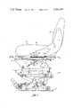
- FIG. 1is a view in side elevation of a seat suspension embodying the principles of this invention
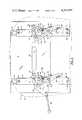
- FIG. 2is a view in section, taken on the plane of the line 2--2 in FIG. 1, showing the means for controlling fore-and-aft seat motion, in the condition that provides for fore-and-aft shock isolation;
- FIG. 3is a view generally similar to FIG. 2, but showing the apparatus in its condition wherein fore-and-aft shock isolation is cut out and the seat part is confined against fore-and-aft motion;
- FIG. 4is a view generally similar to FIG. 2, but showing the apparatus in its condition wherein the seat part is released for fore-and-aft adjustment;
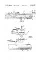
- FIG. 5is a detail sectional view taken on the plane of the line 5--5 in FIG. 2;
- FIG. 6is a fragmentary view in vertical section, taken on the plane of the line 6--6 in FIG. 2;
- FIG. 7is an exploded perspective view of the parts of the mechanism that are shown in FIG. 6.
- a seat suspension embodying the principles of this inventioncomprises a base part 5 that is intended to be secured to a vehicle chassis or the like and a seat part 6 that is connected with the base part by means of suspension structure designated generally by 7.
- the seat part 6, as is conventional,comprises a generally horizontal member 8 that can be in the nature of a cushion, and it preferably has a back rest 9 that projects up from the rear of the horizontal member.
- the suspension structure 7can be regarded as comprising three subassemblies, each performing a substantially distinctive function but each having some components in common with at least one of the other subassemblies.
- the lowermost of these subassembliesprovides for relative up and down shock isolating motion between the base part 5 and the seat part 6, and it comprises the base part, an intermediate carriage 11 that comprises a rectangular, generally horizontal frame, and a scissors linkage 12 that is connected between the base part 5 and the intermediate carriage 11 to confine the latter to vertical substantially translatory motion relative to the base part.
- a resilient device 14Also connected between the base part 5 and the intermediate carriage 11 is a resilient device 14, here illustrated as a coiled compression spring.
- the second subassemblyprovides for height adjustment of the seat and comprises the intermediate carriage 11, an upper carriage 16, and an adjustable parallelogram linkage 17 that is connected between the two carriages 11 and 16.
- the third subassemblylocated just below the seat part 6, provides for fore-and-aft adjustment and fore-and-aft shock isolation of the seat part. It comprises a pair of fore-and-aft extending guide rails 18, mounted on the top of the upper carriage 16 near its opposite sides, and a pair of channel-like guide ways 19 which are secured to the underside of the seat part 6 and which cooperate with the respective guide rails 18 to confine the seat part to fore-and-aft motion relative to the upper carriage 16.
- the two lower subassembliesmay be generally conventional but as far as the present invention is concerned, the portion of the suspension that is at and below the level of the guide rails is merely representative of any supporting structure which is substantially confined against fore-and-aft motion and on which a seat is guided for fore-and-aft motion.
- the guide ways 19 that slide on the relatively fixed rails 18comprise elongated channels which are secured to the seat part 6 at their opposite ends by means of short, downwardly projecting spacers 84. Balls 85 are confined between the rails 18 and guide ways 19 in a known arrangement, for a freely sliding connection between them.
- Two essentially identical control devices 86one at each side of the suspension, provide for fore-and-aft seat adjustment and for cutting in and cutting out fore-and-aft isolation.
- the two control devices 86are connected for operation in unison, as explained hereinafter.
- Each control device 86is located in the space between a guide way 19 and the underside of the seat part 6, and it comprises a latching member 87 and a control member 88 that is swingable by means of an actuating handle 89.
- Each latching member 87has a flat, elongated top portion 90 that overlies the top surface of the guideway channel 19 and wherein there is a lengthwise extending slot 91 through which a front shoulder rivet 92 extends to connect the latching member with the guide way.
- the tongue 93is thus engaged in a notch 94 when the latching member 87 is in a normal locking position, and such engagement holds the latching member against lengthwise motion relative to the underlying rail 18.
- Each latching member 87can swing to and from its locking position about the vertical axis defined by the front shoulder rivet 92 that connects it with the guideway channel 19, and it is biased toward that position by means of a coiled tension spring 95 that has a rear end connected to the guideway channel 19 at a distance behind the latching member and has its front end connected to a lug 96 on the latching member that is spaced both laterally from its slot 91 and to the rear thereof.
- the guideway channel 19 to which it is connected by the rivet 92can move lengthwise relative to it through a distance defined by engagement of that rivet against the ends of the slot 91, and the tension spring 95 tends to draw the guideway 19 forwardly and thus imposes a forward bias upon the seat part 6.
- each latching member 87Overlying the flat top portion 90 of each latching member 87 is its control member 88, which is substantially flat and has a triangular notch or cutout 97 therein through which the front shoulder rivet 92 extends.
- a large diameter washer-like disc 98confined under the head of the rivet 92, overlies the top surface of the control member 88 to confine it to edgewise motion.
- the control member 88Behind the triangular cutout 97 the control member 88 has a pivot connection 99 with the latching member 87, comprising a rear shoulder rivet and providing for substantially horizontal edgewise swinging of the control member 88 relative to the latching member 87.
- Such swinging motionis imparted to one of the two control members 88 by means of the lever handle 89, which is accessible at one side of the suspension, and the other control member is constrained to swing in unison with it by a tie strut 101 that has, at its opposite ends, pivot connections 102 with the respective control members, at corresponding locations on the control members that are spaced, in each case, from both the cutout 97 and the rear rivet 99.
- control handle 89is in a forward position, illustrated in FIG. 2, so that each control member 88 is in a position wherein an elongated portion of its triangular cutout 97 is in register with the whole of the slot 91 in its underlying latching member 87, and therefore, the control member 88 leaves the latching member in its normal locking position and presents no interference to sliding of the front shoulder rivet 92 in the slot 91.
- the tension spring 95reacts between the latching member 87 and the guideway channel 19 to urge the latter forwardly.
- a rearward biasing forceis also exerted upon the channel 19 by another tension spring 103 that has its front end connected to the washer-like disc 98, and thus to the front shoulder rivet 92 and the channel 19, and has its rear end connected to a lug 104 on the rear end portion of the control member 88, which lug is captive because the control member 88 is fixed in relation to the latching member 87 at rear rivet 99, the latter, is locked by its tongue 93 to the upper carriage 16.
- the front shoulder rivet 92is centered along the length of the slot 91 in the latching member, the rearward biasing force which the spring 103 exerts upon the guideway channel 19 through said shoulder rivet 92 is equal to the forward biasing force which the spring 95 exerts directly upon the same channel.
- the two springs 95 and 103thus tend to hold the guideway channel 19 in the mid fore-and-aft position at which the front shoulder rivet 92 is midway between the ends of the slot 91, establishing a nominal or static position for the seat; and as the seat moves either forward or rearward from that position it meets with yielding but increasing resistance by which it is urged back to that position.
- each control member 88is swung edgewise about its pivot connection 99 to a position in which the front shoulder rivet 92 is in an apex portion of the triangular cutout 97, so that the control member 88 cooperates with the latching member 87 to prevent fore-and-aft motion of the front shoulder rivet 92 relative to the rail channel 18 to which the latching member 87 is locked, thus confining the guideways 19 and the seat part 6 against fore-and-aft motion.
- the lug 104 on the control member 88, to which the rear end of the spring 103 is connected,is spaced a substantial distance behind the rear shoulder rivet 99 about which the control member swings. Therefore, as each control member 88 is swung between its FIG. 2 position and its FIG. 3 position, its tension spring 103 swings across the pivotal connection 99 and provides a toggle bias upon the control member that tends to maintain it in the selected one of those two positons.
- the lever handle 89is swung to a rearmost position shown in FIG. 4. As it moves to that position, it pivots about the front shoulder rivet 92, and therefore, by reason of its connection 99 with the latching member 87, it swings the latter out of its normal position and to an adjusting position in which the tongue or latch part 93 is disengaged from the notches 94 in the rail channel 18, so that the seat part 6 can be freely slid back and forth relative to the upper carriage 16.
- the latching member 87is swung to this releasing position against a biasing force exerted upon it by the tension spring 95, so that upon release of the lever handle 89 the latching member 87 tends to return to its normal position.
- the front shoulder rivet 92is centered between the ends of the slot 91 in the latching member, so that when the lever handle is subsequently returned to its forward position (FIG. 2) for fore-and-aft isolation, the static position of the seat part 6 will be the same as its adjusted position.
- this inventionprovides a seat suspension which has simple and very efficient provision for independent fore-and-aft adjustment combined with provision for fore-and-aft shock isolation that can be selectively cut in or cut out.
Landscapes
- Engineering & Computer Science (AREA)
- Aviation & Aerospace Engineering (AREA)
- Transportation (AREA)
- Mechanical Engineering (AREA)
- Seats For Vehicles (AREA)
Abstract
Description
Claims (4)
Priority Applications (1)
| Application Number | Priority Date | Filing Date | Title |
|---|---|---|---|
| US06/142,339US4344597A (en) | 1980-04-21 | 1980-04-21 | Vehicle seat with fore-and-aft shock isolation |
Applications Claiming Priority (1)
| Application Number | Priority Date | Filing Date | Title |
|---|---|---|---|
| US06/142,339US4344597A (en) | 1980-04-21 | 1980-04-21 | Vehicle seat with fore-and-aft shock isolation |
Publications (1)
| Publication Number | Publication Date |
|---|---|
| US4344597Atrue US4344597A (en) | 1982-08-17 |
Family
ID=22499471
Family Applications (1)
| Application Number | Title | Priority Date | Filing Date |
|---|---|---|---|
| US06/142,339Expired - LifetimeUS4344597A (en) | 1980-04-21 | 1980-04-21 | Vehicle seat with fore-and-aft shock isolation |
Country Status (1)
| Country | Link |
|---|---|
| US (1) | US4344597A (en) |
Cited By (20)
| Publication number | Priority date | Publication date | Assignee | Title |
|---|---|---|---|---|
| US5364060A (en)* | 1993-03-19 | 1994-11-15 | Milsco Manufacturing Company | Adjustable mechanized seat suspension |
| US5538326A (en)* | 1994-11-14 | 1996-07-23 | Milsco Manufacturing Company | Flexible unitary seat shell |
| US5720462A (en)* | 1995-03-31 | 1998-02-24 | Sears Manufacturing Company | Rotatable and fore-aft slidable seat mount and controls |
| US6382718B1 (en)* | 1998-12-24 | 2002-05-07 | Daimlerchrysler Ag | Automatically fastenable vehicle seat |
| US20040056501A1 (en)* | 2002-09-19 | 2004-03-25 | Philippe Chareyre | Device and system for filtering vibrational movements of a passenger support, and passenger support equipped with such a system |
| US20040144906A1 (en)* | 2002-11-15 | 2004-07-29 | Milsco Manufacturing, A Unit Of Jason Inc. | Vehicle seat suspension and method |
| US20050285006A1 (en)* | 2004-06-28 | 2005-12-29 | Koutsky L J | Vehicle seat suspension with stabilized isolator |
| US20080252114A1 (en)* | 2007-04-16 | 2008-10-16 | Volvo Construction Equipment Holding Sweden Ab. | Seat for heavy equipment having buffer means in forward and backward directions |
| US20080252127A1 (en)* | 2007-04-16 | 2008-10-16 | Volvo Construction Equipment Holding Sweden Ab. | Height adjustment device for heavy equipment console box having weight balancing |
| US20110285183A1 (en)* | 2008-09-05 | 2011-11-24 | Jeffrey Joseph Poniatowski | Adjuster and hinge for child booster seat |
| DE102012112525A1 (en)* | 2012-12-18 | 2014-06-18 | Grammer Ag | Commercial vehicle seat with Doppelarretierbarem cross slide part |
| ITMO20130002A1 (en)* | 2013-01-10 | 2014-07-11 | Seat S R L | SEALED SEAT WITH IMPROVED ADJUSTMENT. |
| DE102014107816A1 (en)* | 2014-06-03 | 2015-12-03 | Grammer Ag | Commercial vehicle seat with lockable slide |
| US9211812B2 (en) | 2012-12-18 | 2015-12-15 | Grammer Ag | Utility vehicle seat with integrated rotation adjustment device |
| US9227529B2 (en) | 2012-12-18 | 2016-01-05 | Grammer Ag | Utility vehicle seat with a rotation adjustment device overload protection unit |
| WO2016105730A1 (en)* | 2014-12-22 | 2016-06-30 | Caterpillar Inc. | Seat suspension system |
| US9566886B2 (en) | 2012-12-12 | 2017-02-14 | Grammer Ag | Vehicle seat |
| US9579995B2 (en) | 2012-12-18 | 2017-02-28 | Grammer Ag | Commercial vehicle seat with rotatable seat part |
| US9688173B2 (en) | 2014-07-01 | 2017-06-27 | Grammer Ag | Suspension system for vehicles and method for fitting vehicle parts with suspension |
| CN114261415A (en)* | 2021-12-13 | 2022-04-01 | 中车株洲电力机车有限公司 | Driving seat swinging support mechanism |
Citations (11)
| Publication number | Priority date | Publication date | Assignee | Title |
|---|---|---|---|---|
| US2834396A (en)* | 1955-03-21 | 1958-05-13 | Rockwell Spring & Axle Co | Seat support |
| US3100617A (en)* | 1960-07-22 | 1963-08-13 | Bostrom Mfg Company | Vehicle seat fore and aft shock isolator |
| US3188045A (en)* | 1961-08-25 | 1965-06-08 | Wilmot Breeden Ltd | Lockable adjustment means |
| US3190592A (en)* | 1962-11-06 | 1965-06-22 | Jr Joseph E Grizzle | Shock absorber for vehicle seats |
| CA737270A (en)* | 1966-06-28 | American Metal Products Company | Seat track | |
| US3258241A (en)* | 1964-11-12 | 1966-06-28 | Bostrom Corp | Vehicle seat suspension |
| FR1467257A (en)* | 1965-12-17 | 1967-01-27 | Tubauto | Device for height adjustment of vehicle seats |
| US3325137A (en)* | 1965-07-30 | 1967-06-13 | Knudsen Patrick | Flexible vehicle seat mount |
| US3335996A (en)* | 1965-09-10 | 1967-08-15 | Bostrom Corp | Variable damping control for seats |
| US3390857A (en)* | 1965-06-09 | 1968-07-02 | Nordpatent Ab | Resilient car-seat carriage |
| US4228984A (en)* | 1978-11-13 | 1980-10-21 | Deere & Company | Vibration attenuator seat |
- 1980
- 1980-04-21USUS06/142,339patent/US4344597A/ennot_activeExpired - Lifetime
Patent Citations (11)
| Publication number | Priority date | Publication date | Assignee | Title |
|---|---|---|---|---|
| CA737270A (en)* | 1966-06-28 | American Metal Products Company | Seat track | |
| US2834396A (en)* | 1955-03-21 | 1958-05-13 | Rockwell Spring & Axle Co | Seat support |
| US3100617A (en)* | 1960-07-22 | 1963-08-13 | Bostrom Mfg Company | Vehicle seat fore and aft shock isolator |
| US3188045A (en)* | 1961-08-25 | 1965-06-08 | Wilmot Breeden Ltd | Lockable adjustment means |
| US3190592A (en)* | 1962-11-06 | 1965-06-22 | Jr Joseph E Grizzle | Shock absorber for vehicle seats |
| US3258241A (en)* | 1964-11-12 | 1966-06-28 | Bostrom Corp | Vehicle seat suspension |
| US3390857A (en)* | 1965-06-09 | 1968-07-02 | Nordpatent Ab | Resilient car-seat carriage |
| US3325137A (en)* | 1965-07-30 | 1967-06-13 | Knudsen Patrick | Flexible vehicle seat mount |
| US3335996A (en)* | 1965-09-10 | 1967-08-15 | Bostrom Corp | Variable damping control for seats |
| FR1467257A (en)* | 1965-12-17 | 1967-01-27 | Tubauto | Device for height adjustment of vehicle seats |
| US4228984A (en)* | 1978-11-13 | 1980-10-21 | Deere & Company | Vibration attenuator seat |
Cited By (38)
| Publication number | Priority date | Publication date | Assignee | Title |
|---|---|---|---|---|
| US5364060A (en)* | 1993-03-19 | 1994-11-15 | Milsco Manufacturing Company | Adjustable mechanized seat suspension |
| US5538326A (en)* | 1994-11-14 | 1996-07-23 | Milsco Manufacturing Company | Flexible unitary seat shell |
| US5599069A (en)* | 1994-11-14 | 1997-02-04 | Milsco Manufacturing Company | Flexible unitary seat shell including base section having frame sockets |
| US5720462A (en)* | 1995-03-31 | 1998-02-24 | Sears Manufacturing Company | Rotatable and fore-aft slidable seat mount and controls |
| US6382718B1 (en)* | 1998-12-24 | 2002-05-07 | Daimlerchrysler Ag | Automatically fastenable vehicle seat |
| US6857674B2 (en)* | 2002-09-19 | 2005-02-22 | Airbus France | Device and system for filtering vibrational movements of a passenger support, and passenger support equipped with such a system |
| US20040056501A1 (en)* | 2002-09-19 | 2004-03-25 | Philippe Chareyre | Device and system for filtering vibrational movements of a passenger support, and passenger support equipped with such a system |
| US7185867B2 (en) | 2002-11-15 | 2007-03-06 | Milsco Manufacturing Company, A Unit Of Jason Incorporated | Vehicle seat suspension and method |
| US20040144906A1 (en)* | 2002-11-15 | 2004-07-29 | Milsco Manufacturing, A Unit Of Jason Inc. | Vehicle seat suspension and method |
| US7922142B2 (en)* | 2004-06-28 | 2011-04-12 | Sears Manufacturing Co. | Vehicle seat suspension with stabilized isolator |
| GB2415620B (en)* | 2004-06-28 | 2008-07-16 | Sears Mfg Co | Vehicle seat suspension with stabilised isolator |
| US20050285006A1 (en)* | 2004-06-28 | 2005-12-29 | Koutsky L J | Vehicle seat suspension with stabilized isolator |
| GB2415620A (en)* | 2004-06-28 | 2006-01-04 | Sears Mfg Co | Vehicle seat suspension with stabilised isolator |
| CN101289157B (en)* | 2007-04-16 | 2013-09-11 | 沃尔沃建造设备控股(瑞典)有限公司 | Height adjustment device for heavy equipment console box having weight balancing |
| US20080252114A1 (en)* | 2007-04-16 | 2008-10-16 | Volvo Construction Equipment Holding Sweden Ab. | Seat for heavy equipment having buffer means in forward and backward directions |
| US20080252127A1 (en)* | 2007-04-16 | 2008-10-16 | Volvo Construction Equipment Holding Sweden Ab. | Height adjustment device for heavy equipment console box having weight balancing |
| JP2008265741A (en)* | 2007-04-16 | 2008-11-06 | Volvo Construction Equipment Ab | Seat for construction machine provided with shock absorbing means in longitudinal direction |
| EP1982865A3 (en)* | 2007-04-16 | 2009-10-21 | Volvo Construction Equipment Holding Sweden AB | Height adjustment device for heavy equipment console box having weight balancing |
| EP1982864A3 (en)* | 2007-04-16 | 2009-10-21 | Volvo Construction Equipment Holding Sweden AB | Seat for heavy equipment having buffer means in forward and backward directions |
| US8079438B2 (en) | 2007-04-16 | 2011-12-20 | Volvo Construction Equipment Holdings Sweden Ab | Seat for heavy equipment having buffer means in forward and backward directions |
| CN101289071B (en)* | 2007-04-16 | 2012-11-07 | 沃尔沃建造设备控股(瑞典)有限公司 | Seat for heavy equipment having buffer means in forward and backward directions |
| US20110285183A1 (en)* | 2008-09-05 | 2011-11-24 | Jeffrey Joseph Poniatowski | Adjuster and hinge for child booster seat |
| US8894151B2 (en)* | 2008-09-05 | 2014-11-25 | Clek Inc. | Adjuster and hinge for child booster seat |
| US9566886B2 (en) | 2012-12-12 | 2017-02-14 | Grammer Ag | Vehicle seat |
| DE102012112525B4 (en)* | 2012-12-18 | 2017-12-28 | Grammer Ag | Commercial vehicle seat with Doppelarretierbarem cross slide part |
| US9579995B2 (en) | 2012-12-18 | 2017-02-28 | Grammer Ag | Commercial vehicle seat with rotatable seat part |
| DE102012112525A1 (en)* | 2012-12-18 | 2014-06-18 | Grammer Ag | Commercial vehicle seat with Doppelarretierbarem cross slide part |
| US9211812B2 (en) | 2012-12-18 | 2015-12-15 | Grammer Ag | Utility vehicle seat with integrated rotation adjustment device |
| US9227529B2 (en) | 2012-12-18 | 2016-01-05 | Grammer Ag | Utility vehicle seat with a rotation adjustment device overload protection unit |
| US9085245B2 (en) | 2012-12-18 | 2015-07-21 | Grammer Ag | Commercial vehicle seat comprising a double-catch cross slide part |
| ITMO20130002A1 (en)* | 2013-01-10 | 2014-07-11 | Seat S R L | SEALED SEAT WITH IMPROVED ADJUSTMENT. |
| US9663001B2 (en) | 2014-06-03 | 2017-05-30 | Grammer Ag | Utility vehicle with lockable slide part |
| DE102014107816A1 (en)* | 2014-06-03 | 2015-12-03 | Grammer Ag | Commercial vehicle seat with lockable slide |
| DE102014107816B4 (en) | 2014-06-03 | 2018-05-03 | Grammer Aktiengesellschaft | Commercial vehicle seat with lockable cross-slide part |
| US9688173B2 (en) | 2014-07-01 | 2017-06-27 | Grammer Ag | Suspension system for vehicles and method for fitting vehicle parts with suspension |
| WO2016105730A1 (en)* | 2014-12-22 | 2016-06-30 | Caterpillar Inc. | Seat suspension system |
| CN114261415A (en)* | 2021-12-13 | 2022-04-01 | 中车株洲电力机车有限公司 | Driving seat swinging support mechanism |
| CN114261415B (en)* | 2021-12-13 | 2023-08-08 | 中车株洲电力机车有限公司 | A driving seat swing support mechanism |
Similar Documents
| Publication | Publication Date | Title |
|---|---|---|
| US4344597A (en) | Vehicle seat with fore-and-aft shock isolation | |
| US4382573A (en) | Vehicle seat support with incorporated device for damping longitudinal acceleration | |
| US4678232A (en) | Headrest assembly for vehicles | |
| US7152839B2 (en) | Vehicle seating system with improved vibration isolation | |
| US5251864A (en) | Suspension device for vehicle seat | |
| US5765802A (en) | Low profile seat suspension | |
| US6773049B2 (en) | Adjustable seat suspension for utility vehicle | |
| US4265482A (en) | Head-rest adjusting device | |
| US4384701A (en) | Fore and aft adjustment and isolation assembly | |
| US4477050A (en) | Multi-directional vibration attenuator seat | |
| US3954245A (en) | Vehicle seat and support assembly therefor | |
| US4455009A (en) | Adjustable vehicle seat mounting device | |
| US4015877A (en) | Vehicle seat assemblies | |
| US3100617A (en) | Vehicle seat fore and aft shock isolator | |
| GB1587328A (en) | Vehicle seats | |
| US4500062A (en) | Adjustable seat leveling mechanism | |
| US9878643B2 (en) | Juvenile vehicle seat with headrest adjustor | |
| US4241893A (en) | Adjustable seat assembly | |
| US4606578A (en) | Head-rest | |
| GB1401794A (en) | Movable seat for a motor vehicle | |
| GB2240710A (en) | Vehicle seat which is adjustable relative to pivotable backrest | |
| US4666208A (en) | Walk-in mechanism associated with seat track structure | |
| US3711149A (en) | Vehicle seat | |
| US3437373A (en) | Seat assembly | |
| US5011109A (en) | Suspension device for seat |
Legal Events
| Date | Code | Title | Description |
|---|---|---|---|
| AS | Assignment | Owner name:MILSCO MANUFACTURING COMPANY MILWAUKEE WIS A CORP Free format text:ASSIGNMENT OF ASSIGNORS INTEREST.;ASSIGNOR:EIMEN, SHAWN H.;REEL/FRAME:003939/0082 Effective date:19800411 | |
| STCF | Information on status: patent grant | Free format text:PATENTED CASE | |
| AS | Assignment | Owner name:FIRST NATIONAL BANK OF CHICAGO, THE, ILLINOIS Free format text:THIRD AMENDMENT TO PATENT AND LICENSE SECURITY AGREEMENT;ASSIGNOR:JASON INCORPORATED;REEL/FRAME:007289/0398 Effective date:19950103 | |
| AS | Assignment | Owner name:JASON, INCORPORATED, WISCONSIN Free format text:ASSIGNMENT OF ASSIGNORS INTEREST;ASSIGNOR:MILSCO MANUFACTURING COMPANY;REEL/FRAME:007388/0433 Effective date:19950103 | |
| AS | Assignment | Owner name:JASON INCORPORATED, WISCONSIN Free format text:RELEASE BY SECURED PARTY;ASSIGNOR:THE FIRST NATIONAL BANK OF CHICAGO;REEL/FRAME:025320/0665 Effective date:20000816 |