US4344092A - Miniature video camera means for video system - Google Patents
Miniature video camera means for video systemDownload PDFInfo
- Publication number
- US4344092A US4344092AUS06/199,380US19938080AUS4344092AUS 4344092 AUS4344092 AUS 4344092AUS 19938080 AUS19938080 AUS 19938080AUS 4344092 AUS4344092 AUS 4344092A
- Authority
- US
- United States
- Prior art keywords
- video
- circuit
- video camera
- imaging
- opening
- Prior art date
- Legal status (The legal status is an assumption and is not a legal conclusion. Google has not performed a legal analysis and makes no representation as to the accuracy of the status listed.)
- Expired - Lifetime
Links
- 238000003384imaging methodMethods0.000claimsabstractdescription78
- 230000003287optical effectEffects0.000claimsabstractdescription37
- 239000004020conductorSubstances0.000claimsdescription11
- 239000000758substrateSubstances0.000claimsdescription4
- 239000010409thin filmSubstances0.000claimsdescription4
- 230000005669field effectEffects0.000claimsdescription3
- 239000010408filmSubstances0.000claimsdescription3
- 230000008878couplingEffects0.000claims4
- 238000010168coupling processMethods0.000claims4
- 238000005859coupling reactionMethods0.000claims4
- 230000000694effectsEffects0.000description4
- 239000002131composite materialSubstances0.000description3
- 238000000034methodMethods0.000description3
- RYGMFSIKBFXOCR-UHFFFAOYSA-NCopperChemical compound[Cu]RYGMFSIKBFXOCR-UHFFFAOYSA-N0.000description2
- 238000004891communicationMethods0.000description2
- 238000010276constructionMethods0.000description2
- 229910052802copperInorganic materials0.000description2
- 239000010949copperSubstances0.000description2
- 230000000593degrading effectEffects0.000description2
- 230000035945sensitivityEffects0.000description2
- 238000001356surgical procedureMethods0.000description2
- 230000005540biological transmissionEffects0.000description1
- 230000002860competitive effectEffects0.000description1
- 238000010586diagramMethods0.000description1
- 238000005516engineering processMethods0.000description1
- 238000003475laminationMethods0.000description1
- 239000000463materialSubstances0.000description1
- 239000002184metalSubstances0.000description1
- 229910052751metalInorganic materials0.000description1
Images

Classifications
- A—HUMAN NECESSITIES
- A61—MEDICAL OR VETERINARY SCIENCE; HYGIENE
- A61B—DIAGNOSIS; SURGERY; IDENTIFICATION
- A61B1/00—Instruments for performing medical examinations of the interior of cavities or tubes of the body by visual or photographical inspection, e.g. endoscopes; Illuminating arrangements therefor
- A61B1/04—Instruments for performing medical examinations of the interior of cavities or tubes of the body by visual or photographical inspection, e.g. endoscopes; Illuminating arrangements therefor combined with photographic or television appliances
- A61B1/042—Instruments for performing medical examinations of the interior of cavities or tubes of the body by visual or photographical inspection, e.g. endoscopes; Illuminating arrangements therefor combined with photographic or television appliances characterised by a proximal camera, e.g. a CCD camera
- H—ELECTRICITY
- H04—ELECTRIC COMMUNICATION TECHNIQUE
- H04N—PICTORIAL COMMUNICATION, e.g. TELEVISION
- H04N23/00—Cameras or camera modules comprising electronic image sensors; Control thereof
- H04N23/40—Circuit details for pick-up tubes
- H—ELECTRICITY
- H04—ELECTRIC COMMUNICATION TECHNIQUE
- H04N—PICTORIAL COMMUNICATION, e.g. TELEVISION
- H04N23/00—Cameras or camera modules comprising electronic image sensors; Control thereof
- H04N23/50—Constructional details
Definitions
- This inventionrelates to a miniature video camera means adapted for use in video systems and more particularly to a small, compact video camera head having a housing which is substantially the same size as a vidicon tube and yoke and which includes circuit means for preamplifying and driving a coaxial cable in a direct wire television system with an amplified video signal.
- a video camera head for a closed circuit television systemis disclosed in U.S. Pat. No. 4,028,730 to Frederick A. Miller, inventor of the invention described herein and having a common assignee.
- the video camera head described in U.S. Pat. No. 4,028,730is a small compact, lightweight, color video camera and includes a vidicon tube and two printed circuit boards, one of which is positioned between the opening of the metal housing and the vidicon tube and the other of which is located between the rear of the videcon tube and the housing.
- a first printed circuit boardis utilized for the preamplifying means for producing an amplified, video signal which is then applied to the second printed circuit board located at the opposite end of the housing wherein the electrical video signal is amplified by an amplifying means and applied to an emitter-follower amplifier means to drive a coaxial cable with an amplified electrical video signal.
- the electrical video signalsit becomes more difficult to recover the video signal produced from the video imaging means. It is desirable for the electrical video signals to have a signal to noise ratio of more than forty (40) decibels.
- the length of electrical conductors which extend from printed circuit boards in the video camera head and the capacitive effect thereofresults in additional noise into the electrical video signal which reduces the signal to noise ratio of the electrical video signal in the associated television systems.
- the present inventionovercomes several disadvantages associated with the miniaturization of color video camera means and video imaging means used therein by minimizing the noise which is introduced into the electrical video signal during the preamplification thereof before the amplified video signal is applied to an output circuit such as for example, a coaxial cable in a closed circuit television system.
- the present inventiondiscloses a miniature video camera means for use in a video system.
- the video camera meansincludes a video imaging means for producing an electrical video signal and includes an imaging surface for receiving an optical image thereon and for generating an electrical video signal representing the optical image.
- an electromagnetic deflection yokeis used.
- a housingencloses the video imaging means and includes means for defining an opening therethrough at one end thereof enabling an optical image to impinge upon the imaging surface of the video imaging means.
- the housingencloses and supports the video imaging means with the imaging surface spaced in axial alignment with and a predetermined distance from the opening.
- Circuit meansare provided which can be formed into any desired geometrical shape and which define a passageway which is adapted to pass an optical image.
- the circuit meansis located in the housing between the opening and the imaging surface of the video imaging means and is positioned with the passageway relative to the opening and imaging surface such that the optical image is passed therethrough and impinges upon the imaging surface of the video imaging means.
- the circuit meansincludes preamplifying means and driving means for applying an amplified electrical video signal to an output circuit which forms part of a video or television system.
- One advantage of the present inventionis that very small video imaging means may be utilized which have diameters in the order of about 1/2", 5/8", and 2/3" to about 1.00", lengths in the order of about 2" to 3" and a weight in the order of 1 ounce.
- circuit meanscan be formed of any construction such as thick film, thin film, printed circuit board, integrated circuit elements, wired electrical components and the like.
- a yet further advantage of the present inventionis that the preamplifying means of the circuit means can be specifically designed, positioned on the circuit means located in the opening or distance between the opening in the housing end and imaging surface and have circuit characteristics which result in performance characteristics of a miniaturized color video camera which are similar to those of larger competitive video camera means.
- the miniaturized color video camera meanshas electrical characteristics which are equivalent to that of larger cameras including sensitivity, resolution and chroma.
- a still yet further advantage of the present inventionis that the video camera means is electrically connected by a shielded coaxial cable to processor circuitry which is located remote to the video camera means.
- processor circuitrywhich is located remote to the video camera means.
- low impedance horizontal drive circuits and a low impedance horizontal electromagnetic deflection yoke having an inductance of less than 0.5 millihenriescan be utilized with the video imaging means without affecting sensitivity, resolution, or chroma of the video signal generated thereby.
- video imaging means having electrostatic deflecting meanscould likewise to used herein.
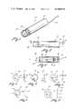
- FIG. 1is a perspective view of a miniature video camera means utilizing the teaching of this present invention
- FIG. 2is a top plan view of a video camera means
- FIG. 3is a partial sectional view of the video camera means taken along section lines 3--3 of FIG. 2;
- FIGS. 4 (a) and 4 (b)are pictorial representations of an annular shaped circuit means having an annular shaped passageway;
- FIGS. 5 (a) and 5 (b)are pictorial representations of a cylindrical shaped circuit means which includes a hollowed out central area which defines a passageway;
- FIGS. 6 (a) and 6 (b)are pictorial representations of a two segment semi-circular circuit means which defines a passageway therebetween;
- FIGS. 7 (a) and 7 (b)are pictorial representations of rectangular shaped circuit means having an annular shaped passageway;
- FIGS. 8 (a) and 8 (b)are pictorial representations of an oval shaped circuit means having an optical shaped means defining a passageway;
- FIG. 9is a schematic diagram of the electrical circuitry of the circuit means including a preamplifying means, driving curcuit means and an output circuit.
- FIG. 1illustrates a miniature video camera means shown generally by arrow 18 which is adapted for use in a video system.
- the video camera meansis adapted for use in a closed circuit, direct wire television system.
- the video camera meanscould have wide application including use in any type of a video system, television system, broadcasting system, any type of radio requency transmission system or the like.
- the video camera means illustrated in FIG. 1includes a housing 20 which encloses and supports a video imaging means which is illustrated in greater detail in FIG. 3.
- the video camera means 18includes a housing 20 which encloses and supports a video imaging means.
- the housing 20includes means for defining an opening, shown generally as 22, which is adapted to pass an optical image from an optical device, such as for example lens 26, which is located exterior to the housing 20, through the housing 20 onto the imaging surface of a video imaging means.
- FIG. 2illustrates the housing 20, the opening 22, an output circuit 24 in the form of a coaxial cable and lens 26.
- the term "output circuit"is utilized to cover any type of output means such as one or more wires, a coaxial cable, video processing circuitry or the like.
- the amplified electric video signal produced by the video camera means 18is supplied by a coaxial cable to video processing circuitry not shown.
- any type of communication meanssuch as a microwave transmitter, direct wire, or other similar type of communication could be utilized to transmit the electrical video signal produced by the video camera means 18.
- FIG. 3illustrates the details and construction of the video camera means which includes a video imaging means 30 which includes an imaging surface 32 for receiving an optical image thereon.
- the video imaging means 30generates a video signal representing an optical image received from an optical device such as for example from lens 26.
- the optical imagecould be produced from a variety of optical devices external to the housing 20.
- the video cameracan be operatively coupled at the end of the housing to a device which produces an optical image of the interior of a human body such as for example an endoscope.
- the video camera meanscould be operatively connected to an optical device such as a microscope or the like in order to produce an electrical video signal representative of an optical image applied to the imaging surface of the video imaging means 30.
- a video imaging means 30comprised a vidicon tube having electrostatic focus and electromagnetic deflection.
- a vidicon tubehaving electrostatic focus and electromagnetic deflection.
- One example of such a vidicon tubeis that offered for sale by Matsushita Corporation as type S4094 having a 2/3" diameter.
- the length of the vidicon tube, without socket,is approximately 3.0".
- the imaging surfaceutilizes a stripped two color filter in order to recover the color information from the optical image.
- the video imaging meansis a color video imaging means and includes means for generating an electrical video signal having the appropriate video imaging means blanking signals formed therein.
- the composite video signalis produced by a video processing circuit which is located remote to the video camera means.
- the video processing circuitry located remote from the video camera meansreceives the amplified video signal and produces a composite video signal having appropriate blanking, horizontal synchronizing signals, vertical synchronizing signals, color burst signals and any other electrical signals required to produce information contained within a composite video signal.
- the housing 20includes means for defining the opening 22 which is adapted to pass an optical image therethrough and to permit the optical image to impinge upon the imaging surface 32 of the video imaging means 30.
- the video imaging meansis a vidicon tube 30.
- electromagnetic deflection yoke 34is positioned around the periphery of vidicon tube 30 and functions as an electromagnetic deflection means.
- a circuit meanswhich in the preferred embodiment is a printed circuit board 40 having a plurality of electrical components mounted thereon, is formed into a predetermined geometrical shape which defines a passageway which is adapted to pass an optical image through the opening 22 of the housing 20 onto the imaging surface 32 of the video imaging means 30.
- the circuit meanscan be one or more sections or segments formed into a number of predetermined geometrical shapes and can be fabricated by using any one of several known techniques.
- FIGS. 4 (a) and 4 (b)pictorially represent a circuit means which is annular shaped and in the form of a printed circuit board 50 which is constructed using known lamination techniques. The electrical components may be installed on sides 52 and 54 of the printed circuit board 50.
- the predetermined geometrical shape of the circuit meansincludes an annular shaped opening or aperture 56 which defines a passage-way which is adapted to pass an optical image.
- the circuit meansis located in the housing at the location of the circuit means 40 as illustrated in FIG. 3, between the opening 22 and the imaging surface 32 such that the passageway 56 of the printed circuit board 50 is positioned relative to the opening 22 and the imaging surface 32 to pass the optical image from the opening 22, through the passageway 56 onto the imaging surface 32.
- FIGS. 5 (a) and 5 (b)An alternate embodiment of the printed circuit board is illustrated in FIGS. 5 (a) and 5 (b) wherein the printed circuit board 60 is a cylindrical shaped circuit means which includes an outer surface 64 and an inner surface 62 and includes a hollowed out central area which defines a passageway 66. Electrical components can be mounted on the cylindrical shaped printed circuit board 60 on either the exterior surface 64 or the inner surface 62, with care being taken that the geometrical dimension of the electrical components on the inner surface 62 does not interfere with the optical image passing through the passageway 66.
- FIGS. 6 (a) and 6 (b)illustrates that the circuit means can be a double segmented or two segmented semi-circular device having an upper segment 70 and a lower segment 72. Electrical components can be mounted on side 74 or side 78.
- the two segments 70 and 72are semi-circular in shape and define a passageway 76 which is located therebetween.
- the printed circuit board 80can be rectangular in shape having a geometrical dimension which would enable the same to be inserted into the same position between the video camera means 18 within housing 20 in substantially the same position as circuit means 40 is illustrated in FIG. 3.
- the printed circuit board 80 of FIG. 7has a rectangular shaped exterior section and includes an aperture or opening which defines a passageway 86. Components can be mounted on the rectangular shaped printed circuit board 80 on surface 82 or 84.
- FIG. 90Another embodiment of the printed circuit board is illustrated by oval shaped printed circuit board 90 which includes printed circuit board.
- the printed circuit boardis formed of an insulating base material having copper conductors laminated thereto wherein the copper conductors are fabricated into a predetermined pattern.
- Electrical components in terms of integrated circuitrydiscreet components such as field effect transistors, npn transistors and pnp transistors can be mounted upon the so-formed printed circuit board.
- the circuit meanscould be in the form of a single specially designed integrated circuit element such as a large scale integrated circuit, could be fabricated of a plurality of integrated circuit components, could be formed by thin film techniques, thick film substrates, thin film substrates, wired components or any combinations thereof.
- the electrical video signalmust be applied to the circuit means without significant loss of the electrical video signal produced by the video imaging means.
- the so produced electrical signalhas a desired signal to noise ratio of about 40 decibels or better and the impedance of the video imaging means is extremely high on the order of about 200 megohms and it is necessary to apply the same to the circuit means with minimal loss to the electrical video signal.
- the frequency response of the electrical video signalis in excess of 4 MegaHertz and the circuit means must be able to handle this frequency response.
- the output of the preamplifying meansmust be of a low impedance, in the order of about 75 ohms, in order to effectively apply the same to an output means.
- the length of the electrical conductor between the video imaging means and the circuit meanshas a capacitance associated therewith.
- the electrical video signal produced by the video imaging meansbe applied to a high impedance input preamplifying means to immediately and promptly preserve the signal to noise ratio of the electrical video signal before that signal is then transmitted along electrical conductors or applied by some type of a driving circuit means to an output circuit.
- lead 110 and the so produced electrical video signalis applied to a means responsive to the electrical video signal producing a preamplified electric video signal which has a signal to noise ratio which is not degraded relative to that received from the video imaging means 102.
- the means for producing the preamplified video signalis in the form of a high impedance preamplifying means, such as for example a field effect transistor 120 which is operatively coupled to the voltage amplifier means, such as for example, a pnp voltage amplifier transistor 122.
- the amplified electrical video signalis applied to a driving circuit means 126 which in turn is operatively coupled to an output circuit which is a coaxial cable 130.
- the driving circuit means 126is an emitter-follower amplifying means which may be the form of an npn transistor.
- the coaxial cable 130applies the amplified electrical video signal to video processing circuitry located remote from the device.
- the impedance of the emitter-follower transistor 126is appropriately matched to the impedance of the coaxial cable to provide for maximum power transfer to the output circuit.
- the video imaging meansis a vidicon tube and is represented by the video imaging means 102.
- the impedance of the horizontal drive of the vidicon tubeis selected to be at a value such that a low impedance horizontal electromagnetic deflection yoke has an inductance of less than 0.5 millihenries.
- the horizontal coil of the electromagnetic deflection yokeis illustrated by element 104 in FIG. 9.
- the impedance of the horizontal deflection coil 104is selected such that the horizontal scanning signals which are produced external from the video camera means, are applied to the video imaging means to develop the desired scan pattern.
- the electrical conductors which carry the horizontal scanning signalsare one of many conductors in a shielded cable which extends from the video camera means to the video processing circuitry.
- the other conductorsare utilized to carry other signals to the video imaging means and includes a coaxial cable for carrying the amplified video signal from the video imaging means to the video processing circuitry.
- the low impedance of the horizontal coilenables the video processing circuit to apply the horizontal scanning signals to the horizontal deflection coil 104 over the shielded cable without degrading the video signal produced by the video imaging means.
Landscapes
- Engineering & Computer Science (AREA)
- Health & Medical Sciences (AREA)
- Life Sciences & Earth Sciences (AREA)
- Multimedia (AREA)
- Signal Processing (AREA)
- Surgery (AREA)
- Radiology & Medical Imaging (AREA)
- Heart & Thoracic Surgery (AREA)
- Optics & Photonics (AREA)
- Pathology (AREA)
- Biophysics (AREA)
- Physics & Mathematics (AREA)
- Biomedical Technology (AREA)
- Nuclear Medicine, Radiotherapy & Molecular Imaging (AREA)
- Medical Informatics (AREA)
- Molecular Biology (AREA)
- Animal Behavior & Ethology (AREA)
- General Health & Medical Sciences (AREA)
- Public Health (AREA)
- Veterinary Medicine (AREA)
- Studio Devices (AREA)
Abstract
Description
Claims (11)
Priority Applications (1)
| Application Number | Priority Date | Filing Date | Title |
|---|---|---|---|
| US06/199,380US4344092A (en) | 1980-10-21 | 1980-10-21 | Miniature video camera means for video system |
Applications Claiming Priority (1)
| Application Number | Priority Date | Filing Date | Title |
|---|---|---|---|
| US06/199,380US4344092A (en) | 1980-10-21 | 1980-10-21 | Miniature video camera means for video system |
Publications (1)
| Publication Number | Publication Date |
|---|---|
| US4344092Atrue US4344092A (en) | 1982-08-10 |
Family
ID=22737266
Family Applications (1)
| Application Number | Title | Priority Date | Filing Date |
|---|---|---|---|
| US06/199,380Expired - LifetimeUS4344092A (en) | 1980-10-21 | 1980-10-21 | Miniature video camera means for video system |
Country Status (1)
| Country | Link |
|---|---|
| US (1) | US4344092A (en) |
Cited By (59)
| Publication number | Priority date | Publication date | Assignee | Title |
|---|---|---|---|---|
| US4394692A (en)* | 1981-11-27 | 1983-07-19 | Vicon Industries, Inc. | Housing assembly for an electrical apparatus |
| US4491865A (en)* | 1982-09-29 | 1985-01-01 | Welch Allyn, Inc. | Image sensor assembly |
| EP0146644A1 (en)* | 1983-12-07 | 1985-07-03 | Lemke GmbH | Miniature television camera and associated screen-monitor unit |
| US4600938A (en)* | 1984-02-07 | 1986-07-15 | Circon Corporation | Focusable video camera for use with endoscopes |
| US4600949A (en)* | 1982-09-25 | 1986-07-15 | Konishiroku Photo Industry Co., Ltd. | Video camera |
| US4600940A (en)* | 1984-02-07 | 1986-07-15 | Circon Corporation | Video camera for use with an endoscope and method for making same |
| US4600939A (en)* | 1984-02-07 | 1986-07-15 | Circon Corporation | Focusable video camera for use with endoscopes |
| US4639772A (en)* | 1984-02-07 | 1987-01-27 | Circon Corporation | Focusable video camera for use with endoscopes |
| US4677471A (en)* | 1985-08-16 | 1987-06-30 | Olympus Optical Co., Ltd. | Endoscope |
| US4722000A (en)* | 1986-10-01 | 1988-01-26 | Medical Concepts Incorporated | Adapter for endoscopic camera |
| US4807594A (en)* | 1988-01-15 | 1989-02-28 | Medical Concepts, Incorporated | Adapter assembly for endoscopic video camera |
| USD349340S (en) | 1992-10-19 | 1994-08-02 | Catheter Imaging Systems | Catheter imaging light source |
| US5423311A (en)* | 1992-07-06 | 1995-06-13 | Catheter Imaging Systems | Catheter imaging apparatus |
| US5438265A (en)* | 1993-09-23 | 1995-08-01 | At&T Corp. | Metallic cable-locating apparatus and method having an image capturing means |
| USD364180S (en) | 1994-09-14 | 1995-11-14 | Scott Park | Search camera |
| USD364883S (en) | 1993-12-09 | 1995-12-05 | Scott Park | Search camera |
| US5495286A (en)* | 1991-07-22 | 1996-02-27 | Adair; Edwin L. | Sterile video microscope holder for operating room |
| US5644237A (en)* | 1995-09-27 | 1997-07-01 | At&T | Method and apparatus for precisely locating a buried utility conveyance |
| USD398986S (en) | 1996-01-16 | 1998-09-29 | Catheter Imaging Systems, Inc. | Handle interface for steerable catheter |
| US5846221A (en)* | 1996-02-09 | 1998-12-08 | Catheter Imaging Systems, Inc. | Steerable catheter having disposable module and sterilizable handle and method of connecting same |
| US5857996A (en)* | 1992-07-06 | 1999-01-12 | Catheter Imaging Systems | Method of epidermal surgery |
| USD405881S (en) | 1996-01-16 | 1999-02-16 | Catheter Imaging Systems, Inc. | Handle for steerable catheter |
| US6002437A (en)* | 1996-07-15 | 1999-12-14 | Sony Corporation | Camera head having a flexible printed circuit board with thin folding portions arranged in a cylindrical housing |
| US6007531A (en)* | 1995-11-21 | 1999-12-28 | Catheter Imaging Systems, Inc. | Steerable catheter having disposable module and sterilizable handle and method of connecting same |
| US20030137588A1 (en)* | 2002-01-23 | 2003-07-24 | Guan-Wu Wang | Wireless camera system |
| USD510589S1 (en)* | 2003-03-28 | 2005-10-11 | Apple Computer, Inc. | Camera |
| USD547346S1 (en)* | 2004-03-09 | 2007-07-24 | V.I.O., Inc. | Camera |
| USD563444S1 (en)* | 2006-08-15 | 2008-03-04 | Banner Engineering Corporation | Digital camera |
| USD564558S1 (en)* | 2004-03-09 | 2008-03-18 | V.I.O. Inc. | Camera |
| USD601606S1 (en)* | 2008-08-08 | 2009-10-06 | Ethicon Endo-Surgery, Inc. | Camera handle |
| US20140200513A1 (en)* | 2012-10-22 | 2014-07-17 | Olympus Medical Systems Corp. | Endoscope |
| WO2020023543A1 (en)* | 2018-07-24 | 2020-01-30 | Magic Leap, Inc. | Viewing device with dust seal integration |
| US10878235B2 (en) | 2015-02-26 | 2020-12-29 | Magic Leap, Inc. | Apparatus for a near-eye display |
| US10914949B2 (en) | 2018-11-16 | 2021-02-09 | Magic Leap, Inc. | Image size triggered clarification to maintain image sharpness |
| US11092812B2 (en) | 2018-06-08 | 2021-08-17 | Magic Leap, Inc. | Augmented reality viewer with automated surface selection placement and content orientation placement |
| US11112862B2 (en) | 2018-08-02 | 2021-09-07 | Magic Leap, Inc. | Viewing system with interpupillary distance compensation based on head motion |
| US11187923B2 (en) | 2017-12-20 | 2021-11-30 | Magic Leap, Inc. | Insert for augmented reality viewing device |
| US11189252B2 (en) | 2018-03-15 | 2021-11-30 | Magic Leap, Inc. | Image correction due to deformation of components of a viewing device |
| US11200870B2 (en) | 2018-06-05 | 2021-12-14 | Magic Leap, Inc. | Homography transformation matrices based temperature calibration of a viewing system |
| US11199713B2 (en) | 2016-12-30 | 2021-12-14 | Magic Leap, Inc. | Polychromatic light out-coupling apparatus, near-eye displays comprising the same, and method of out-coupling polychromatic light |
| US11204491B2 (en) | 2018-05-30 | 2021-12-21 | Magic Leap, Inc. | Compact variable focus configurations |
| US11210808B2 (en) | 2016-12-29 | 2021-12-28 | Magic Leap, Inc. | Systems and methods for augmented reality |
| US11216086B2 (en) | 2018-08-03 | 2022-01-04 | Magic Leap, Inc. | Unfused pose-based drift correction of a fused pose of a totem in a user interaction system |
| US11280937B2 (en) | 2017-12-10 | 2022-03-22 | Magic Leap, Inc. | Anti-reflective coatings on optical waveguides |
| US11425189B2 (en) | 2019-02-06 | 2022-08-23 | Magic Leap, Inc. | Target intent-based clock speed determination and adjustment to limit total heat generated by multiple processors |
| US11445232B2 (en) | 2019-05-01 | 2022-09-13 | Magic Leap, Inc. | Content provisioning system and method |
| US11510027B2 (en) | 2018-07-03 | 2022-11-22 | Magic Leap, Inc. | Systems and methods for virtual and augmented reality |
| US11514673B2 (en) | 2019-07-26 | 2022-11-29 | Magic Leap, Inc. | Systems and methods for augmented reality |
| US11567324B2 (en) | 2017-07-26 | 2023-01-31 | Magic Leap, Inc. | Exit pupil expander |
| US11579441B2 (en) | 2018-07-02 | 2023-02-14 | Magic Leap, Inc. | Pixel intensity modulation using modifying gain values |
| US11598651B2 (en) | 2018-07-24 | 2023-03-07 | Magic Leap, Inc. | Temperature dependent calibration of movement detection devices |
| US11737832B2 (en) | 2019-11-15 | 2023-08-29 | Magic Leap, Inc. | Viewing system for use in a surgical environment |
| US11762623B2 (en) | 2019-03-12 | 2023-09-19 | Magic Leap, Inc. | Registration of local content between first and second augmented reality viewers |
| US11856479B2 (en) | 2018-07-03 | 2023-12-26 | Magic Leap, Inc. | Systems and methods for virtual and augmented reality along a route with markers |
| US11885871B2 (en) | 2018-05-31 | 2024-01-30 | Magic Leap, Inc. | Radar head pose localization |
| US12016719B2 (en) | 2018-08-22 | 2024-06-25 | Magic Leap, Inc. | Patient viewing system |
| US12033081B2 (en) | 2019-11-14 | 2024-07-09 | Magic Leap, Inc. | Systems and methods for virtual and augmented reality |
| US12044851B2 (en) | 2018-12-21 | 2024-07-23 | Magic Leap, Inc. | Air pocket structures for promoting total internal reflection in a waveguide |
| US12164978B2 (en) | 2018-07-10 | 2024-12-10 | Magic Leap, Inc. | Thread weave for cross-instruction set architecture procedure calls |
Citations (1)
| Publication number | Priority date | Publication date | Assignee | Title |
|---|---|---|---|---|
| US4028730A (en)* | 1976-05-17 | 1977-06-07 | Circon Corporation | Vidicon camera for closed circuit television system |
- 1980
- 1980-10-21USUS06/199,380patent/US4344092A/ennot_activeExpired - Lifetime
Patent Citations (1)
| Publication number | Priority date | Publication date | Assignee | Title |
|---|---|---|---|---|
| US4028730A (en)* | 1976-05-17 | 1977-06-07 | Circon Corporation | Vidicon camera for closed circuit television system |
Non-Patent Citations (1)
| Title |
|---|
| Proceedings of the National Aerospace Electronics Conference, Dayton, Ohio, 1971.* |
Cited By (90)
| Publication number | Priority date | Publication date | Assignee | Title |
|---|---|---|---|---|
| US4394692A (en)* | 1981-11-27 | 1983-07-19 | Vicon Industries, Inc. | Housing assembly for an electrical apparatus |
| US4600949A (en)* | 1982-09-25 | 1986-07-15 | Konishiroku Photo Industry Co., Ltd. | Video camera |
| US4491865A (en)* | 1982-09-29 | 1985-01-01 | Welch Allyn, Inc. | Image sensor assembly |
| EP0146644A1 (en)* | 1983-12-07 | 1985-07-03 | Lemke GmbH | Miniature television camera and associated screen-monitor unit |
| US4600938A (en)* | 1984-02-07 | 1986-07-15 | Circon Corporation | Focusable video camera for use with endoscopes |
| US4600940A (en)* | 1984-02-07 | 1986-07-15 | Circon Corporation | Video camera for use with an endoscope and method for making same |
| US4600939A (en)* | 1984-02-07 | 1986-07-15 | Circon Corporation | Focusable video camera for use with endoscopes |
| US4639772A (en)* | 1984-02-07 | 1987-01-27 | Circon Corporation | Focusable video camera for use with endoscopes |
| US4677471A (en)* | 1985-08-16 | 1987-06-30 | Olympus Optical Co., Ltd. | Endoscope |
| US4722000A (en)* | 1986-10-01 | 1988-01-26 | Medical Concepts Incorporated | Adapter for endoscopic camera |
| US4807594A (en)* | 1988-01-15 | 1989-02-28 | Medical Concepts, Incorporated | Adapter assembly for endoscopic video camera |
| US5495286A (en)* | 1991-07-22 | 1996-02-27 | Adair; Edwin L. | Sterile video microscope holder for operating room |
| US5423311A (en)* | 1992-07-06 | 1995-06-13 | Catheter Imaging Systems | Catheter imaging apparatus |
| US5857996A (en)* | 1992-07-06 | 1999-01-12 | Catheter Imaging Systems | Method of epidermal surgery |
| US6925323B2 (en) | 1992-07-06 | 2005-08-02 | Phillip Jack Snoke | System for enhancing visibility in the epidural space |
| US6470209B2 (en) | 1992-07-06 | 2002-10-22 | Catheter Imaging Systems, Inc. | System for enhancing visibility in the epidural space |
| US6464682B1 (en) | 1992-07-06 | 2002-10-15 | Catheter Imaging Systems, Inc. | Method of epidural surgery |
| US6010493A (en)* | 1992-07-06 | 2000-01-04 | Catheter Imaging Systems | Method of epidural surgery |
| USD349340S (en) | 1992-10-19 | 1994-08-02 | Catheter Imaging Systems | Catheter imaging light source |
| US5438265A (en)* | 1993-09-23 | 1995-08-01 | At&T Corp. | Metallic cable-locating apparatus and method having an image capturing means |
| USD364883S (en) | 1993-12-09 | 1995-12-05 | Scott Park | Search camera |
| USD364180S (en) | 1994-09-14 | 1995-11-14 | Scott Park | Search camera |
| US5644237A (en)* | 1995-09-27 | 1997-07-01 | At&T | Method and apparatus for precisely locating a buried utility conveyance |
| US6007531A (en)* | 1995-11-21 | 1999-12-28 | Catheter Imaging Systems, Inc. | Steerable catheter having disposable module and sterilizable handle and method of connecting same |
| US6017322A (en)* | 1995-11-21 | 2000-01-25 | Catheter Imaging Systems, Inc. | Steerable catheter having disposable module and sterilizable handle and method of connecting same |
| US5860953A (en)* | 1995-11-21 | 1999-01-19 | Catheter Imaging Systems, Inc. | Steerable catheter having disposable module and sterilizable handle and method of connecting same |
| USD398986S (en) | 1996-01-16 | 1998-09-29 | Catheter Imaging Systems, Inc. | Handle interface for steerable catheter |
| USD405881S (en) | 1996-01-16 | 1999-02-16 | Catheter Imaging Systems, Inc. | Handle for steerable catheter |
| US5846221A (en)* | 1996-02-09 | 1998-12-08 | Catheter Imaging Systems, Inc. | Steerable catheter having disposable module and sterilizable handle and method of connecting same |
| US6002437A (en)* | 1996-07-15 | 1999-12-14 | Sony Corporation | Camera head having a flexible printed circuit board with thin folding portions arranged in a cylindrical housing |
| US20030137588A1 (en)* | 2002-01-23 | 2003-07-24 | Guan-Wu Wang | Wireless camera system |
| US7129986B2 (en)* | 2002-01-23 | 2006-10-31 | Guan-Wu Wang | Wireless camera system |
| USD510589S1 (en)* | 2003-03-28 | 2005-10-11 | Apple Computer, Inc. | Camera |
| USD547346S1 (en)* | 2004-03-09 | 2007-07-24 | V.I.O., Inc. | Camera |
| USD564558S1 (en)* | 2004-03-09 | 2008-03-18 | V.I.O. Inc. | Camera |
| USD563444S1 (en)* | 2006-08-15 | 2008-03-04 | Banner Engineering Corporation | Digital camera |
| USD601606S1 (en)* | 2008-08-08 | 2009-10-06 | Ethicon Endo-Surgery, Inc. | Camera handle |
| US20140200513A1 (en)* | 2012-10-22 | 2014-07-17 | Olympus Medical Systems Corp. | Endoscope |
| US9986900B2 (en)* | 2012-10-22 | 2018-06-05 | Olympus Corporation | Endoscope |
| US11347960B2 (en) | 2015-02-26 | 2022-05-31 | Magic Leap, Inc. | Apparatus for a near-eye display |
| US10878235B2 (en) | 2015-02-26 | 2020-12-29 | Magic Leap, Inc. | Apparatus for a near-eye display |
| US11756335B2 (en) | 2015-02-26 | 2023-09-12 | Magic Leap, Inc. | Apparatus for a near-eye display |
| US12131500B2 (en) | 2016-12-29 | 2024-10-29 | Magic Leap, Inc. | Systems and methods for augmented reality |
| US11790554B2 (en) | 2016-12-29 | 2023-10-17 | Magic Leap, Inc. | Systems and methods for augmented reality |
| US11210808B2 (en) | 2016-12-29 | 2021-12-28 | Magic Leap, Inc. | Systems and methods for augmented reality |
| US11874468B2 (en) | 2016-12-30 | 2024-01-16 | Magic Leap, Inc. | Polychromatic light out-coupling apparatus, near-eye displays comprising the same, and method of out-coupling polychromatic light |
| US11199713B2 (en) | 2016-12-30 | 2021-12-14 | Magic Leap, Inc. | Polychromatic light out-coupling apparatus, near-eye displays comprising the same, and method of out-coupling polychromatic light |
| US11927759B2 (en) | 2017-07-26 | 2024-03-12 | Magic Leap, Inc. | Exit pupil expander |
| US11567324B2 (en) | 2017-07-26 | 2023-01-31 | Magic Leap, Inc. | Exit pupil expander |
| US11953653B2 (en) | 2017-12-10 | 2024-04-09 | Magic Leap, Inc. | Anti-reflective coatings on optical waveguides |
| US12298473B2 (en) | 2017-12-10 | 2025-05-13 | Magic Leap, Inc. | Anti-reflective coatings on optical waveguides |
| US11280937B2 (en) | 2017-12-10 | 2022-03-22 | Magic Leap, Inc. | Anti-reflective coatings on optical waveguides |
| US11762222B2 (en) | 2017-12-20 | 2023-09-19 | Magic Leap, Inc. | Insert for augmented reality viewing device |
| US12366769B2 (en) | 2017-12-20 | 2025-07-22 | Magic Leap, Inc. | Insert for augmented reality viewing device |
| US11187923B2 (en) | 2017-12-20 | 2021-11-30 | Magic Leap, Inc. | Insert for augmented reality viewing device |
| US11908434B2 (en) | 2018-03-15 | 2024-02-20 | Magic Leap, Inc. | Image correction due to deformation of components of a viewing device |
| US11189252B2 (en) | 2018-03-15 | 2021-11-30 | Magic Leap, Inc. | Image correction due to deformation of components of a viewing device |
| US11776509B2 (en) | 2018-03-15 | 2023-10-03 | Magic Leap, Inc. | Image correction due to deformation of components of a viewing device |
| US11204491B2 (en) | 2018-05-30 | 2021-12-21 | Magic Leap, Inc. | Compact variable focus configurations |
| US11885871B2 (en) | 2018-05-31 | 2024-01-30 | Magic Leap, Inc. | Radar head pose localization |
| US11200870B2 (en) | 2018-06-05 | 2021-12-14 | Magic Leap, Inc. | Homography transformation matrices based temperature calibration of a viewing system |
| US11092812B2 (en) | 2018-06-08 | 2021-08-17 | Magic Leap, Inc. | Augmented reality viewer with automated surface selection placement and content orientation placement |
| US11579441B2 (en) | 2018-07-02 | 2023-02-14 | Magic Leap, Inc. | Pixel intensity modulation using modifying gain values |
| US12001013B2 (en) | 2018-07-02 | 2024-06-04 | Magic Leap, Inc. | Pixel intensity modulation using modifying gain values |
| US11856479B2 (en) | 2018-07-03 | 2023-12-26 | Magic Leap, Inc. | Systems and methods for virtual and augmented reality along a route with markers |
| US11510027B2 (en) | 2018-07-03 | 2022-11-22 | Magic Leap, Inc. | Systems and methods for virtual and augmented reality |
| US12164978B2 (en) | 2018-07-10 | 2024-12-10 | Magic Leap, Inc. | Thread weave for cross-instruction set architecture procedure calls |
| US12379981B2 (en) | 2018-07-10 | 2025-08-05 | Magic Leap, Inc. | Thread weave for cross-instruction set architectureprocedure calls |
| US11624929B2 (en) | 2018-07-24 | 2023-04-11 | Magic Leap, Inc. | Viewing device with dust seal integration |
| US12247846B2 (en) | 2018-07-24 | 2025-03-11 | Magic Leap, Inc. | Temperature dependent calibration of movement detection devices |
| WO2020023543A1 (en)* | 2018-07-24 | 2020-01-30 | Magic Leap, Inc. | Viewing device with dust seal integration |
| US11598651B2 (en) | 2018-07-24 | 2023-03-07 | Magic Leap, Inc. | Temperature dependent calibration of movement detection devices |
| US11112862B2 (en) | 2018-08-02 | 2021-09-07 | Magic Leap, Inc. | Viewing system with interpupillary distance compensation based on head motion |
| US11630507B2 (en) | 2018-08-02 | 2023-04-18 | Magic Leap, Inc. | Viewing system with interpupillary distance compensation based on head motion |
| US11216086B2 (en) | 2018-08-03 | 2022-01-04 | Magic Leap, Inc. | Unfused pose-based drift correction of a fused pose of a totem in a user interaction system |
| US11609645B2 (en) | 2018-08-03 | 2023-03-21 | Magic Leap, Inc. | Unfused pose-based drift correction of a fused pose of a totem in a user interaction system |
| US11960661B2 (en) | 2018-08-03 | 2024-04-16 | Magic Leap, Inc. | Unfused pose-based drift correction of a fused pose of a totem in a user interaction system |
| US12254141B2 (en) | 2018-08-03 | 2025-03-18 | Magic Leap, Inc. | Unfused pose-based drift correction of a fused pose of a totem in a user interaction system |
| US12016719B2 (en) | 2018-08-22 | 2024-06-25 | Magic Leap, Inc. | Patient viewing system |
| US10914949B2 (en) | 2018-11-16 | 2021-02-09 | Magic Leap, Inc. | Image size triggered clarification to maintain image sharpness |
| US11521296B2 (en) | 2018-11-16 | 2022-12-06 | Magic Leap, Inc. | Image size triggered clarification to maintain image sharpness |
| US12044851B2 (en) | 2018-12-21 | 2024-07-23 | Magic Leap, Inc. | Air pocket structures for promoting total internal reflection in a waveguide |
| US11425189B2 (en) | 2019-02-06 | 2022-08-23 | Magic Leap, Inc. | Target intent-based clock speed determination and adjustment to limit total heat generated by multiple processors |
| US11762623B2 (en) | 2019-03-12 | 2023-09-19 | Magic Leap, Inc. | Registration of local content between first and second augmented reality viewers |
| US12267545B2 (en) | 2019-05-01 | 2025-04-01 | Magic Leap, Inc. | Content provisioning system and method |
| US11445232B2 (en) | 2019-05-01 | 2022-09-13 | Magic Leap, Inc. | Content provisioning system and method |
| US12249035B2 (en) | 2019-07-26 | 2025-03-11 | Magic Leap, Inc. | System and method for augmented reality with virtual objects behind a physical surface |
| US11514673B2 (en) | 2019-07-26 | 2022-11-29 | Magic Leap, Inc. | Systems and methods for augmented reality |
| US12033081B2 (en) | 2019-11-14 | 2024-07-09 | Magic Leap, Inc. | Systems and methods for virtual and augmented reality |
| US11737832B2 (en) | 2019-11-15 | 2023-08-29 | Magic Leap, Inc. | Viewing system for use in a surgical environment |
Similar Documents
| Publication | Publication Date | Title |
|---|---|---|
| US4344092A (en) | Miniature video camera means for video system | |
| US5030963A (en) | Signal receiver | |
| US4615330A (en) | Noise suppressor for electronic endoscope | |
| SE9302420L (en) | Extra antenna element | |
| US4853703A (en) | Microstrip antenna with stripline and amplifier | |
| US20050073612A1 (en) | Television tuner including distribution connectors | |
| JPS60150736A (en) | Delay circuit for ultrasound diagnostic equipment | |
| JP2902734B2 (en) | Solid-state imaging device | |
| JPH05161602A (en) | Solid-state image pickup device and endoscope using the device | |
| US20200069151A1 (en) | Image pickup apparatus and endoscope | |
| JP3316784B2 (en) | Electronic scope connector device | |
| JPH0884278A (en) | Solid-state image pickup device | |
| JPH05293080A (en) | Structure of image receiving part of electronic endoscope | |
| JP3230801B2 (en) | Endoscope | |
| JPH10108049A (en) | Image-pickup device | |
| JPH01198182A (en) | Image pickup device | |
| JPS63290541A (en) | Endoscope | |
| JPH0424018A (en) | Electronic endoscope | |
| JPH09180788A (en) | Coaxial terminal for connecting to printed circuit board and connecting structure for printed circuit board | |
| JPH04106974A (en) | Solid state image sensor | |
| JPH0573109B2 (en) | ||
| JPH06325836A (en) | Connecting structure for parallel strip line cable | |
| JPS5869530A (en) | Endoscope using high frequency knife | |
| JPS63151229A (en) | Receiver | |
| JPS6396803U (en) |
Legal Events
| Date | Code | Title | Description |
|---|---|---|---|
| STCF | Information on status: patent grant | Free format text:PATENTED CASE | |
| AS | Assignment | Owner name:SECURITY PACIFIC NATIONAL BANK, A NATIONAL BANKING Free format text:SECURITY INTEREST;ASSIGNOR:CIRCON CORPORATION, A CORP. OF CA.;REEL/FRAME:004610/0150 Effective date:19860806 | |
| AS | Assignment | Owner name:CONNECTICUT BANK AND TRUST COMPANY, THE Free format text:SECURITY INTEREST;ASSIGNOR:CIRCON CORPORATION;REEL/FRAME:004856/0828 Effective date:19880226 | |
| AS | Assignment | Owner name:CIRCON CORPORATION, A CORP. OF CA Free format text:ASSIGNMENT OF ASSIGNORS INTEREST.;ASSIGNOR:SECURITY PACIFIC NATIONAL BANK;REEL/FRAME:004827/0300 Effective date:19880226 Owner name:CIRCON CORPORATION, A CORP. OF CA,CALIFORNIA Free format text:ASSIGNMENT OF ASSIGNORS INTEREST;ASSIGNOR:SECURITY PACIFIC NATIONAL BANK;REEL/FRAME:004827/0300 Effective date:19880226 | |
| AS | Assignment | Owner name:CIRCON CORPORATION A CORP. OF DE Free format text:0MERGER;ASSIGNOR:CIRCON CORPORATION A CORP. OF CA;REEL/FRAME:005856/0041 Effective date:19871001 Owner name:CIRCON CORPORATION A CORP. OF DE Free format text:RELEASE BY SECURED PARTY;ASSIGNOR:CONNECTICUT BANK AND TRUST, N.A.;REEL/FRAME:005856/0052 Effective date:19900405 | |
| AS | Assignment | Owner name:CHASE MANHATTAN BANK, THE, AS COLLATERAL AGENT, NE Free format text:SECURITY AGREEMENT;ASSIGNOR:CIRCON CORPORATION;REEL/FRAME:011122/0530 Effective date:19991112 | |
| AS | Assignment | Owner name:CIRCON CORPORATION, MASSACHUSETTS Free format text:RELEASE BY SECURED PARTY;ASSIGNOR:JPMORGAN CHASE BANK, AS COLLATERAL AGENT (F/K/A THE CHASE MANHATTAN BANK);REEL/FRAME:015592/0392 Effective date:20031219 |