US4343552A - Nephelometer - Google Patents
NephelometerDownload PDFInfo
- Publication number
- US4343552A US4343552AUS06/107,934US10793479AUS4343552AUS 4343552 AUS4343552 AUS 4343552AUS 10793479 AUS10793479 AUS 10793479AUS 4343552 AUS4343552 AUS 4343552A
- Authority
- US
- United States
- Prior art keywords
- light
- sample
- housing
- nephelometer
- bulb
- Prior art date
- Legal status (The legal status is an assumption and is not a legal conclusion. Google has not performed a legal analysis and makes no representation as to the accuracy of the status listed.)
- Expired - Lifetime
Links
Images


Classifications
- G—PHYSICS
- G01—MEASURING; TESTING
- G01N—INVESTIGATING OR ANALYSING MATERIALS BY DETERMINING THEIR CHEMICAL OR PHYSICAL PROPERTIES
- G01N21/00—Investigating or analysing materials by the use of optical means, i.e. using sub-millimetre waves, infrared, visible or ultraviolet light
- G01N21/17—Systems in which incident light is modified in accordance with the properties of the material investigated
- G01N21/47—Scattering, i.e. diffuse reflection
- G01N21/49—Scattering, i.e. diffuse reflection within a body or fluid
- G01N21/53—Scattering, i.e. diffuse reflection within a body or fluid within a flowing fluid, e.g. smoke
Definitions
- This inventionrelates to a nephelometer, which is an instrument for measuring the turbidity of a fluid. More specifically, the invention relates to a nephelometer for measuring the amount of solid material in a sample of water.
- nephelometric measurementshave been made by passing an incident beam of light of known intensity upon the sample to be tested and measuring either the amount of light transmitted through the sample or the amount scattered by the solid particles within the sample. See, e.g., U.S. Pat. No. 3,869,209 to Sigrist, or 3,936,192 to Skala.
- nephelometryto indicate measurements made of the scattered light intensity
- turbidimetryto indicate the measurements of the intensity of the transmitted light.
- the term “nephelometry”shall be construed to include turbidimetry, unless the context clearly indicates otherwise, as certain of the improvements made by the present invention are applicable to both sorts of systems.
- Nephelometric measurementshave, in general, required several significant problems to be solved.
- the sample tubein order to measure the light either transmitted or scattered from a fluid sample, the sample tube must be transparent; if the tube's transparency varies over time due to, for example, the collection of dirt on either the inside or the outside of the tube, the measurement will vary over time, so that the instrument will require periodic cleaning and/or adjustment of its output to match a sample of known turbidity.
- This problemhas been discussed in U.S. Pat. No. 3,861,198 but no adequate solution is suggested therein.
- Another problem which occursis leakage into the light sampling tube of stray light from the surrounding environment.
- a further problem of numerous prior art systemsis that they are very expensive to make due to the elaborate circuitry and mechanical construction required.
- a further problem with certain prior art nephelometers and turbidimetersis that the electric bulbs used to supply the incident light vary over time and moreover, do not have sufficiently long lifetimes to allow adequately trouble-free operation although measures have been taken to limit this problem; see U.S. Pat. No. 3,561,875 to Reid.
- Another problem which has occurred in numerous prior art nephelometric systemsis that the instrument is incapable of distinguishing bubbles which are usually harmless in the fluid to be sampled from solid matter in the sample, thus giving erroneous indications of excess turbidity.
- a further problem inherent in certain prior art designsis that the photocells used to sample the turbidity of incident light only measure the intensity of the light falling on a small fraction of the sample and thus do not always provide accurate results.
- a further object of the inventionis to provide a nephelometer which can be made less expensively than those in the prior art.
- a further object of the inventionis to provide a nephelometer which is self-regulating with respect to light intensity.
- Still a further object of the inventionis to provide a nephelometer in which the transparent tube containing the fluid to be sampled is adapted to be kept clean by means of water flow deflectors.
- a further object of the inventionis to provide circuitry for lamp control whereby lamp life is increased and lamp intensity is self-regulated.
- Still a further object of the inventionis to provide bubble rejection circuitry and whereby the effects of bubbles on the nephelometric measurements are minimized.
- the nephelometer of the inventionwhich comprises a cruciform housing containing various elements of the system.
- An electric lamp bulbprovides a light beam incident on a glass sample tube the intensity of which is regulated in accordance with the output of a first photo-detector.
- the photo-detector outputis fed back through amplifying circuitry to power the bulb so that the light transmitted through the sample tube is maintained at a constant value regardless of the color of the sample, or of the transparency of the tube due to dirt accumulating over time, and the like.
- a second photo-detectorpreferably positioned perpendicular to the first, measures the intensity of light scattered from the sample, thus eliminating effects of the color, and only measuring the amount of light actually scattered from solid particles in the fluid sample to be measured.
- Helical flow restrictorsare placed in the input and output sides of the sample tube so as to force the fluid to be measured to travel in a spiral path. The spiral flow path persists during the sample area so as to provide a self-cleaning action to the interior walls of the tube. Additionally, the helical flow restrictors provide a light trap so that any light entering by the sample tube cannot reach the area of sampling.
- the nephelometer of the inventionis contained in a hermaphroditic housing assembled of two identical molded parts whereby construction of the nephelometer is considerably simplified and made much less expensive than those in the prior art.
- bubble rejection circuitryis employed to enable differentiation between bubbles in the sample tube and actual turbidity or solid matter in the sample tube, thus enabling increased accuracy of measurement.
- Lamp ramp circuitryis provided so that the current to the lamp is turned on and off gradually so as to extend bulb life, and a keep-alive current is maintained across the bulb even when nominally off, also extending its life.
- FIG. 1represents an exterior perspective view of a nephelometer according to the invention, including fluid sample line connections and electrical connections;
- FIG. 2is a cross-section taken along line 2--2 of FIG. 1 showing a first interior view of the nephelometer according to the invention, including the optical path used;
- FIG. 3is a second cross-sectional view of the interior of the nephelometer taken along line 3--3 of FIG. 1 and showing the helical flow restrictors and a second view of certain of the optical apparatus;
- FIG. 4is a cross-section taken along the line 4--4 of FIG. 2 which shows how the two housings are made to interlock with one another so that the same molding can be used for both halves of the hermaphroditic housing;
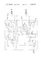
- FIG. 5is a schematic diagram of the nephelometer amplifier circuitry
- FIG. 6is a schematic diagram of the lamp regulator circuitry.
- FIG. 1an overall perspective view of the nephelometer according to the invention is shown. It comprises two identical molded halves 1 and 2, respectively, which are identical and are made in such a way as to mate without modification. Their overall shape is cruciform and they are adapted to have added thereonto extensions 3 and 4, respectively, which permit connections of conventional water tubes 5 and 6. At one end of the cruciform structure, a cap 12 is located, inside which is circuitry to be described in further detail below and from which protrude control and connection wires 9. Inside cap 12 is also located the detector of the scattered light. The light is generated at a second cap 10 covering a bulb which is the source of the illumination.
- the illuminationthus travels towards the opposing end of the nephelometer capped by cap 11 containing circuitry, and to which is attached to heat sink 7.
- the lightpasses through a sample tube which is of glass and which contains water arriving at tube 5 and departing by way of tube 6.
- the sample tube and the tubes 5 and 6are oriented vertically. Some of the light is scattered off and is thus picked up on a photocell concealed beneath cap 12.
- a fourth cap 8corresponds to cap 12 and is filled with a light absorbing material so that there are no double reflections of the light to upset the measurements.
- Caps 8, 10, 11, and 12are so sized as to hold the tube mating halves of the nephelometer 1 and 2 firmly together along parting line 15.
- FIGS. 2 and 3are cross-sections taken along lines 2--2 and 3--3 of FIG. 1, respectively, the internal construction of the nephelometer will be made clear.
- the bulb 20 appearing at the left side of FIG. 2directs light through two lenses 22 and 24 thus focusing the beam of light through an aperture plate 26 at the center of the glass sample tube 28 which serves to minimize stray light.
- the lensesare arranged so that the incident light is normal to the tube 28, thus avoiding refraction. Thence, the light is largely transmitted through the sample onto a diffusion screen 30 angled to reduce the reflection back into the sample tube.
- the diffused lightis then passed to a first photocell 32 which controls, by means of feedback circuitry to be described in further detail below, the intensity of light emitted by bulb 20 so that the amount of light incident on the photocell 32 is essentially independent of the condition of the sample and of the sample tube. In this way, they are automatically compensated for.
- Some fraction of the lightis scattered from any solid material present in the sample tube 28, and is passed through a second pair of lenses 34 and 36, onto a second photocell 38.
- the output of photocell 38thus determines the amount of solid material present in the sample tube, since the amount of light falling on the photocell 38 is a function of the amount of light scattered in the fluid contained with the sample tube 28 which is, in turn, a function of the amount of solid material present therein.
- the output of photocell 38is not affected by any other variations in light transmissivity through the fluid since these are automatically compensated for by the feedback of the signal generated by photocell 32 to bulb 20 thus increasing its intensity in the event that, e.g., the sample tube gets dirty with age or the like.
- the nephelometer body part 2is molded with various recesses and cavities to accommodate the various parts of the nephelometer assembly itself. Specifically, the lenses 22 and 24 and 34 and 36, the aperture screen 26, the diffusion screen 30, the panels holding the two photocells 32 and 38 and that holding the bulb 20 are all held directly by the body. This is done so as to enable simplified assembly, thus reducing the cost of the nephelometer. Similarly, as noted above, the nephelometer halves 1 and 2 are identical thus necessitating, for example, additional recesses to be formed in the right side of the nephelometer shown in FIG. 2.
- the groove 41is adapted to hold aperture ring 26, and groove 42 and 43, lenses 22 and 24, respectively.
- complete symmetrycannot be preserved; vent holes 44 and 45 must be drilled, since their presence in the area of the diffusion screen 30 would cause additional light to fall on it and give misleading readings.
- FIG. 3which is taken along 3--3 of FIG. 1 and of FIG. 2, the orthogonal cross-sectional view of the nephelometer according to the invention is shown.
- Water to be sampledarrives from the right side of the figure via a tube 5 shown in phantom and passes through a helix 50.
- This helixmay desirably be formed by injection molding out of a suitable plastic material and comprises essentially planes at angles to one another.
- a second identical helix 48is provided in the exit 4 of the nephelometer. The use of the second helix 48, while not strictly necessary to cause the helical flow pattern, does tend to keep it regular.
- Both helices 48 and 50comprise more than a full 360° spiral.
- the wateris caused to travel in a spiral path and therefore tends to continue to travel in that same spiral path as it traverses the sample tube 28.
- the effect of the helical flow patternis to scrub the inside walls of the sample tube 28, thus keeping the readings picked up by the two photoelectric cells 32 and 38 relatively constant over time.
- Other methods of cleaning the sample tube 28are possible, such as ultrasonic vibration thereof, but this has so far not proven to be required.
- Another possibilityis to rotate the sample tube at a high enough speed so that the readings tend to average out over time. This introduces some additional complexity in the apparatus, but serves the purpose well. After having been sampled, the water passes through exit helix 48 and a second tube 6 shown in phantom.
- the helixesmay desirably be contained in molded adapters 3 and 4 which can be made identically if carefully designed and adapted to mate with tubes 5 and 6. In a particularly preferred embodiment these are made to mate with a quick connect fastener.
- the helix-containing adapters 3 and 4may be secured to the main halves of the nephelometer 1 and 2 by means of screws or other retaining means.
- O-rings 52 and 54may be provide to seal the glass tube, the two halves of the nephelometer 1 and 2 and the helix adapters 3 and 4. Also shown in FIG.
- FIG. 3due to the view chosen are the lenses 34 and 36 which focus the scattered light on photocell 38, and the join line 15 at which the two halves of the nephelometer body 1 and 2 are joined.
- the caps 8 and 12are shown in FIG. 3 and illustrate how the two halves 1 and 2 of the nephelometer are held together along join line 15.
- aperture plate 26which serves to delimit the size of the incident beam of light passed onto the fluid sample held in sample tube 28 as will be evident from an examination of the optical paths shown in FIG. 2.
- FIG. 4a cross-section is taken along line 4--4 of FIG. 2 and shows how the two halves 1 and 2 of the nephelometer body fit together by means of tongues 56 fitting into grooves 58.
- the two halvescan be made identical and yet can mate without slippage or any necessity of tolerance for fit and can be adapted to seal very well without the necessity of gaskets, glue or other sealing means.
- a groove 60is also provided which runs essentially around part line 15 and which is used to carry the wires from the photocells 32 and 38 and bulb 20 to the power source and other parts of the system within which the nephelometer is used.
- Cap 10is also shown in FIG.
- FIGS. 1, 2, 3, and 4show how it holds the two halves 1 and 2 of the nephelometer together along part line 15.
- the capmay be secured by screws but this is not essential.
- FIGS. 1, 2, 3, and 4one can gain an understanding of the overall construction of the nephelometer according to the invention and of the several inventive features thereof.
- its designis such that the two halves 1 and 2 of the nephelometer not only can be molded identically at vast savings of labor and mold requirements but can also be made to hold the various components of the nephelometer in fixed positions without the necessity of bracketry, riveting, glues, screws, mastics, gaskets and the like.
- the nephelometer body halves 1 and 2are molded of ABS plastic, 20% glass filaments.
- the provision of the groove into which the lamp socket 21 fitsnot only locates the lamp 20 at a predetermined distance from lenses 22 and 24, thus providing a pre-focused beam of light at aperture partition 26, but also serves to locate the panel on which photosensor 32 is located.
- the provision of the grooves 41, 42, and 43 which hold the aperture 26 and the lenses 22 and 24, respectively,means that these parts are located precisely to provide a properly sized focussed light beam and do not require mounting on a separate bracket but can be simply assembled within the two halves of the nephelometer body.
- the cap 8may also be adapted to contain a portion of light absorbing material 40 such a black felt to absorb any stray light which may scatter in that direction from the incidence on the fluid contained in the sample tube 28.
- a portion of light absorbing material 40such as black felt to absorb any stray light which may scatter in that direction from the incidence on the fluid contained in the sample tube 28.
- the surface finishmay be specified to be between 1,000 and 3,000 microinches average peak to valley distance. In this way, any light which is incident on the inside surface of the nephelometer will not be reflected.
- the overall operation of the systemtherefore is substantially as follows.
- waterflows through the system and through the sample tube 28 at a rate of approximately 0.8 gallons per minute.
- the lamp 20provides a high intensity, focused beam of light which travels through the sample tube 28 and illuminates the diffusion screen 30 on its other side.
- the photosensor 32 placed on the other side of diffusion screen 30is operated in a feedback mode to maintain the intensity of illumination provided by lamp 20 at a constant level.
- This through-sample lamp regulation methodthus provides for color rejection, as the amount of light exiting the sample tube is held constant regardless of sample color.
- the diffusion screen 30is used to effectively integrate the light exiting the tube thereby reducing erroneous readings due to particulate matter that may temporarily adhere to the inside surface of the sample tube 28.
- Diffusion screen 30is desirably tilted at approximately 45° in order to reduce any background illumination around the tube produced by reflections off the smooth surface of the screen.
- the inside walls as discussed above of the nephelometerare sandblasted or otherwise formed to a dull black color, thus attenuating any reflected light.
- the small amount of light scattered from the sample in the sample tube 28 due to suspended particles thereinis then focused, by means of lenses 34-36, on the second photosensor 38.
- the signal produced by photosensor 38is then amplified and processed through bubble rejection circuitry and output as a signal desirably between 0 and 10 volts.
- the aperture and lens systemconstrains the sensor to see only the center of the sample tube 28 at which the incident beam is focused. This reduces the background illumination due to inherent imperfections in the glass tube 28 at where the incident beam enters and exits. Since the sample tube 28 is cylindrical and the beam is focused in its center, all the light paths are incident perpendicular to the surface of the tube 28 and no refraction of the light occurs due to passage through the transparent glass or plastic sample tube.
- Bubble rejection circuitryis incorporated in the signal processing circuitry of the invention and it operates by limiting the upward slew rate of the circuitry to about 0.5 volts per second. This allows the differentiation of bubbles from turbidity since the bubbles tend to move through the tube faster, tending to float upward, than the average flow rate.
- Typical sample flow rateis 0.8 gallons per minute representing a bubble velocity of about 5 inches per second for a total optical reflection time of about 40 milliseconds for one bubble flowing past the sensor area.
- a single bubbleproduces a momentary output reading of only 20 millivolts. This effectively cancels erroneous readings due to bursts of bubbles flowing through the sample tube 28.
- Such circiutryis known in the prior art.
- the problemis alleviated first by turning the lamp 20 off except when readings are desired, to reduce the opportunity for algae growth, and second by utlizing in-stream helices 48 and 50.
- the adhesion of particles and bubbles to the inside surface of the sample tube 28is due largely to the formation of a static laminar layer a few thousandths of an inch thick at the water glass interface.
- This static layerdue to the viscosity and surface tension of the water provides a surface for particles and bubbles to adhere to.
- the in-stream helices 48 and 50swirl the incoming water centrifugally to centrally break down the laminar layer and wash the surface of the sample tube 28 clean.
- the velocity of the water at the water/glass interfaceis relatively high and prevents any algae growth or particle build-up to occur.
- the cleaning actionis much the same as water jets constantly washing the surface clean.
- helixeswhich are slightly over one complete revolution serve as light traps preventing any light from entering via the hoses. It will be understood by those skilled in the art that helices disposed in the flow path will be useful to keep viewing ports clean in a wide variety of instrument systems.
- FIG. 5shows the circuitry of the nephelometer amplifier.
- the photocell 38detects the light scattered from the turbidity in the sample tube 28 varying the voltage on the positive input of an operational amplifier 62. This is then amplified, clipped by a diode 64, fed through an integrator stage comprising amplifier 66 and fed back to the input of op-amp 62. Initially both inputs and the output of amp 64 are at 0 volts.
- a diode 68 and a resistor 70provide a stable voltage reference for the photocell 38.
- the trim pot 78is also used to adjust the gain to trim out component tolerances which is done by inserting a sample of known turbidity in the sample tube at installation of the device in a system and adjusting the trim pot 78 until the output is appropriate.
- the photocell 32which is preferably a cadmium sulfide photocell, is used as a feedback element.
- This photocell 32, a resistor 82, a trim pot 84, diodes 85 and 86form a resistive light dependent voltage divider sourcing current to a transistor 88.
- This transistor 88in turn feeds Darlington transistor pair 90 which control the intensity of power delivered from an 8 volt source to the lamp 20.
- Trim pot 84adjusts the closed loop gain to trim the lamp intensity for component variation.
- transistors 92 and 94When a bulb-on input is applied to the base of transistor 92 indicating that the bulb is required, transistor 92 saturates and causes capacitor 96 to discharge through a resistor 98. As the gate voltage to transistor 94 is ramped down, the base of transistor 88 is allowed to ramp up thus causing bulb 20 to gradually light and the loop to close. When the bulb-on input to the base of transistor 92 is pulled low, the transistor 92 opens and capacitor 96 charges through resistors 98 and 99 thus causing the bulb 20 to ramp back down.
- Diode 100 and resistor 101work in conjunction with the Darlington pair 90 to serve two functions; first, to keep a slight voltage on bulb 20 when it is off and second, to turn on transistor 102 when the bulb filament fails.
- diode 100is forward-biased and the Darlington pair 90 is adjusted to provide approximately 0.5 volts on the bulb so as to provide a "keep-alive" current.
- a voltage drop of approximately 0.35 voltsis across resistor 101 keeping transistor 102 off.
- the voltage at the base of transistor pair 90rises from approximately 6 volts to approximately 14 volts raising the voltage across the resistor 101 to about 0.7 volts turning on transistor 102 which may be used to provide a signal that the bulb 20 has burned out.
- a small currentis continuously passed through the bulb keeping the tungsten filament from passing through the 250-350° C. tungsten ductile-brittle transition region which causes bulb failure.
- the circuitramps on and off over approximately 5 seconds. This too allows the bulb to warm up slowly and extends its life substantially.
- this use of intermittent and low current operation of the bulb 20allows the total heat output by the nephelometer to be reduced, which extends component lifetime in general.
- a heat sink 7 as shown in FIG. 1may be mounted on Darlington pair 90 which contro the power supply to the lamp 20.
Landscapes
- Physics & Mathematics (AREA)
- Health & Medical Sciences (AREA)
- Life Sciences & Earth Sciences (AREA)
- Chemical & Material Sciences (AREA)
- Analytical Chemistry (AREA)
- Biochemistry (AREA)
- General Health & Medical Sciences (AREA)
- General Physics & Mathematics (AREA)
- Immunology (AREA)
- Pathology (AREA)
- Investigating Or Analysing Materials By Optical Means (AREA)
Abstract
Description
This invention relates to a nephelometer, which is an instrument for measuring the turbidity of a fluid. More specifically, the invention relates to a nephelometer for measuring the amount of solid material in a sample of water.
It will be apparent that in numerous industrial and other processes it is essential to provide an instrument which is capable of producing an electrical signal indicative of the amount of solid material present in a sample of fluid. It has been known in the prior art for many years, for example, to provide such a signal indicative of the condition of lubricating oil in aircraft engines. See U.S. Pat. Nos. 3,736,431 to Childs; 3,627,423 to Knapp; or 3,892,485 to Merritt et al. Similarly, such apparatus is useful in water purification apparatus for determining whether all solid materials are being filtered from the water. See commonly assigned U.S. Pat. No. 4,145,279 to Selby which describes a water purification system in which the nephelometer of the present invention may play an important part.
Usually nephelometric measurements have been made by passing an incident beam of light of known intensity upon the sample to be tested and measuring either the amount of light transmitted through the sample or the amount scattered by the solid particles within the sample. See, e.g., U.S. Pat. No. 3,869,209 to Sigrist, or 3,936,192 to Skala. A distinction is sometimes drawn between the use of the terms "nephelometry", to indicate measurements made of the scattered light intensity, and "turbidimetry" to indicate the measurements of the intensity of the transmitted light. In this application, the term "nephelometry" shall be construed to include turbidimetry, unless the context clearly indicates otherwise, as certain of the improvements made by the present invention are applicable to both sorts of systems.
Nephelometric measurements have, in general, required several significant problems to be solved. Clearly, in order to measure the light either transmitted or scattered from a fluid sample, the sample tube must be transparent; if the tube's transparency varies over time due to, for example, the collection of dirt on either the inside or the outside of the tube, the measurement will vary over time, so that the instrument will require periodic cleaning and/or adjustment of its output to match a sample of known turbidity. This problem has been discussed in U.S. Pat. No. 3,861,198 but no adequate solution is suggested therein. Another problem which occurs is leakage into the light sampling tube of stray light from the surrounding environment. A further problem of numerous prior art systems is that they are very expensive to make due to the elaborate circuitry and mechanical construction required. A further problem with certain prior art nephelometers and turbidimeters is that the electric bulbs used to supply the incident light vary over time and moreover, do not have sufficiently long lifetimes to allow adequately trouble-free operation although measures have been taken to limit this problem; see U.S. Pat. No. 3,561,875 to Reid. Another problem which has occurred in numerous prior art nephelometric systems is that the instrument is incapable of distinguishing bubbles which are usually harmless in the fluid to be sampled from solid matter in the sample, thus giving erroneous indications of excess turbidity. A further problem inherent in certain prior art designs is that the photocells used to sample the turbidity of incident light only measure the intensity of the light falling on a small fraction of the sample and thus do not always provide accurate results.
It is therefore an object of the invention to provide an improved nephelometer.
A further object of the invention is to provide a nephelometer which can be made less expensively than those in the prior art.
A further object of the invention is to provide a nephelometer which is self-regulating with respect to light intensity.
Still a further object of the invention is to provide a nephelometer in which the transparent tube containing the fluid to be sampled is adapted to be kept clean by means of water flow deflectors.
A further object of the invention is to provide circuitry for lamp control whereby lamp life is increased and lamp intensity is self-regulated.
Still a further object of the invention is to provide bubble rejection circuitry and whereby the effects of bubbles on the nephelometric measurements are minimized.
The above needs of the art and objects of the invention are satisfied by the nephelometer of the invention which comprises a cruciform housing containing various elements of the system. An electric lamp bulb provides a light beam incident on a glass sample tube the intensity of which is regulated in accordance with the output of a first photo-detector. The photo-detector output is fed back through amplifying circuitry to power the bulb so that the light transmitted through the sample tube is maintained at a constant value regardless of the color of the sample, or of the transparency of the tube due to dirt accumulating over time, and the like. A second photo-detector preferably positioned perpendicular to the first, measures the intensity of light scattered from the sample, thus eliminating effects of the color, and only measuring the amount of light actually scattered from solid particles in the fluid sample to be measured. Helical flow restrictors are placed in the input and output sides of the sample tube so as to force the fluid to be measured to travel in a spiral path. The spiral flow path persists during the sample area so as to provide a self-cleaning action to the interior walls of the tube. Additionally, the helical flow restrictors provide a light trap so that any light entering by the sample tube cannot reach the area of sampling. Furthermore, the nephelometer of the invention is contained in a hermaphroditic housing assembled of two identical molded parts whereby construction of the nephelometer is considerably simplified and made much less expensive than those in the prior art. Finally, bubble rejection circuitry is employed to enable differentiation between bubbles in the sample tube and actual turbidity or solid matter in the sample tube, thus enabling increased accuracy of measurement. Lamp ramp circuitry is provided so that the current to the lamp is turned on and off gradually so as to extend bulb life, and a keep-alive current is maintained across the bulb even when nominally off, also extending its life.
The invention will be better understood if reference is made to the accompanying drawings in which:
FIG. 1 represents an exterior perspective view of a nephelometer according to the invention, including fluid sample line connections and electrical connections;
FIG. 2 is a cross-section taken alongline 2--2 of FIG. 1 showing a first interior view of the nephelometer according to the invention, including the optical path used;
FIG. 3 is a second cross-sectional view of the interior of the nephelometer taken alongline 3--3 of FIG. 1 and showing the helical flow restrictors and a second view of certain of the optical apparatus;
FIG. 4 is a cross-section taken along theline 4--4 of FIG. 2 which shows how the two housings are made to interlock with one another so that the same molding can be used for both halves of the hermaphroditic housing;
FIG. 5 is a schematic diagram of the nephelometer amplifier circuitry; and
FIG. 6 is a schematic diagram of the lamp regulator circuitry.
Referring now to FIG. 1, an overall perspective view of the nephelometer according to the invention is shown. It comprises two identicalmolded halves 1 and 2, respectively, which are identical and are made in such a way as to mate without modification. Their overall shape is cruciform and they are adapted to have addedthereonto extensions conventional water tubes cap 12 is located, inside which is circuitry to be described in further detail below and from which protrude control and connection wires 9. Insidecap 12 is also located the detector of the scattered light. The light is generated at asecond cap 10 covering a bulb which is the source of the illumination. The illumination thus travels towards the opposing end of the nephelometer capped by cap 11 containing circuitry, and to which is attached toheat sink 7. The light passes through a sample tube which is of glass and which contains water arriving attube 5 and departing by way oftube 6. Preferably the sample tube and thetubes cap 12. Afourth cap 8 corresponds tocap 12 and is filled with a light absorbing material so that there are no double reflections of the light to upset the measurements.Caps nephelometer 1 and 2 firmly together alongparting line 15.
Referring now to FIGS. 2 and 3, which are cross-sections taken alonglines 2--2 and 3--3 of FIG. 1, respectively, the internal construction of the nephelometer will be made clear. Thebulb 20 appearing at the left side of FIG. 2 directs light through twolenses aperture plate 26 at the center of theglass sample tube 28 which serves to minimize stray light. The lenses are arranged so that the incident light is normal to thetube 28, thus avoiding refraction. Thence, the light is largely transmitted through the sample onto adiffusion screen 30 angled to reduce the reflection back into the sample tube. The diffused light is then passed to afirst photocell 32 which controls, by means of feedback circuitry to be described in further detail below, the intensity of light emitted bybulb 20 so that the amount of light incident on thephotocell 32 is essentially independent of the condition of the sample and of the sample tube. In this way, they are automatically compensated for. Some fraction of the light is scattered from any solid material present in thesample tube 28, and is passed through a second pair oflenses second photocell 38. The output ofphotocell 38 thus determines the amount of solid material present in the sample tube, since the amount of light falling on thephotocell 38 is a function of the amount of light scattered in the fluid contained with thesample tube 28 which is, in turn, a function of the amount of solid material present therein. The output ofphotocell 38 is not affected by any other variations in light transmissivity through the fluid since these are automatically compensated for by the feedback of the signal generated byphotocell 32 tobulb 20 thus increasing its intensity in the event that, e.g., the sample tube gets dirty with age or the like.
It will be noted that thenephelometer body part 2 is molded with various recesses and cavities to accommodate the various parts of the nephelometer assembly itself. Specifically, thelenses aperture screen 26, thediffusion screen 30, the panels holding the twophotocells bulb 20 are all held directly by the body. This is done so as to enable simplified assembly, thus reducing the cost of the nephelometer. Similarly, as noted above, the nephelometer halves 1 and 2 are identical thus necessitating, for example, additional recesses to be formed in the right side of the nephelometer shown in FIG. 2. Thus, for example, thegroove 41 is adapted to holdaperture ring 26, and groove 42 and 43,lenses holes diffusion screen 30 would cause additional light to fall on it and give misleading readings.
Referring now to FIG. 3, which is taken along 3--3 of FIG. 1 and of FIG. 2, the orthogonal cross-sectional view of the nephelometer according to the invention is shown. Water to be sampled arrives from the right side of the figure via atube 5 shown in phantom and passes through ahelix 50. This helix may desirably be formed by injection molding out of a suitable plastic material and comprises essentially planes at angles to one another. A secondidentical helix 48 is provided in theexit 4 of the nephelometer. The use of thesecond helix 48, while not strictly necessary to cause the helical flow pattern, does tend to keep it regular. Bothhelices sample tube 28. The effect of the helical flow pattern is to scrub the inside walls of thesample tube 28, thus keeping the readings picked up by the twophotoelectric cells sample tube 28 are possible, such as ultrasonic vibration thereof, but this has so far not proven to be required. Another possibility is to rotate the sample tube at a high enough speed so that the readings tend to average out over time. This introduces some additional complexity in the apparatus, but serves the purpose well. After having been sampled, the water passes throughexit helix 48 and asecond tube 6 shown in phantom. The helixes may desirably be contained in moldedadapters tubes adapters nephelometer 1 and 2 by means of screws or other retaining means. O-rings 52 and 54 may be provide to seal the glass tube, the two halves of thenephelometer 1 and 2 and thehelix adapters lenses photocell 38, and thejoin line 15 at which the two halves of thenephelometer body 1 and 2 are joined. Thecaps halves 1 and 2 of the nephelometer are held together alongjoin line 15. Also shown in FIG. 3 isaperture plate 26 which serves to delimit the size of the incident beam of light passed onto the fluid sample held insample tube 28 as will be evident from an examination of the optical paths shown in FIG. 2.
Referring now to FIG. 4, a cross-section is taken alongline 4--4 of FIG. 2 and shows how the twohalves 1 and 2 of the nephelometer body fit together by means oftongues 56 fitting intogrooves 58. By this construction, the two halves can be made identical and yet can mate without slippage or any necessity of tolerance for fit and can be adapted to seal very well without the necessity of gaskets, glue or other sealing means. Agroove 60 is also provided which runs essentially aroundpart line 15 and which is used to carry the wires from thephotocells bulb 20 to the power source and other parts of the system within which the nephelometer is used.Cap 10 is also shown in FIG. 4 and shows how it holds the twohalves 1 and 2 of the nephelometer together alongpart line 15. The cap may be secured by screws but this is not essential. Reviewing FIGS. 1, 2, 3, and 4, one can gain an understanding of the overall construction of the nephelometer according to the invention and of the several inventive features thereof. In particular, its design is such that the twohalves 1 and 2 of the nephelometer not only can be molded identically at vast savings of labor and mold requirements but can also be made to hold the various components of the nephelometer in fixed positions without the necessity of bracketry, riveting, glues, screws, mastics, gaskets and the like. In a preferred embodiment, the nephelometer body halves 1 and 2 are molded of ABS plastic, 20% glass filaments. In particular, note how the provision of the groove into which thelamp socket 21 fits not only locates thelamp 20 at a predetermined distance fromlenses aperture partition 26, but also serves to locate the panel on whichphotosensor 32 is located. Similarly, the provision of thegrooves aperture 26 and thelenses cap 8 may also be adapted to contain a portion of light absorbingmaterial 40 such a black felt to absorb any stray light which may scatter in that direction from the incidence on the fluid contained in thesample tube 28. In this connection, it will be noted that it is desirable throughout the interior of the nephelometer to provide a surface finish to its parts which does not tend to reflect light so that all the light in the nephelometer is that in the optical path shown in FIG. 2 so as to retain optical accuracy; the surface finish may be specified to be between 1,000 and 3,000 microinches average peak to valley distance. In this way, any light which is incident on the inside surface of the nephelometer will not be reflected.
The overall operation of the system therefore is substantially as follows. In a particular system embodiment such as that described in the Selby patent referred to above, water flows through the system and through thesample tube 28 at a rate of approximately 0.8 gallons per minute. Thelamp 20 provides a high intensity, focused beam of light which travels through thesample tube 28 and illuminates thediffusion screen 30 on its other side. The photosensor 32 placed on the other side ofdiffusion screen 30 is operated in a feedback mode to maintain the intensity of illumination provided bylamp 20 at a constant level. This through-sample lamp regulation method thus provides for color rejection, as the amount of light exiting the sample tube is held constant regardless of sample color. Thediffusion screen 30 is used to effectively integrate the light exiting the tube thereby reducing erroneous readings due to particulate matter that may temporarily adhere to the inside surface of thesample tube 28.Diffusion screen 30 is desirably tilted at approximately 45° in order to reduce any background illumination around the tube produced by reflections off the smooth surface of the screen. The inside walls as discussed above of the nephelometer are sandblasted or otherwise formed to a dull black color, thus attenuating any reflected light.
The small amount of light scattered from the sample in thesample tube 28 due to suspended particles therein is then focused, by means of lenses 34-36, on thesecond photosensor 38. The signal produced byphotosensor 38 is then amplified and processed through bubble rejection circuitry and output as a signal desirably between 0 and 10 volts. The aperture and lens system constrains the sensor to see only the center of thesample tube 28 at which the incident beam is focused. This reduces the background illumination due to inherent imperfections in theglass tube 28 at where the incident beam enters and exits. Since thesample tube 28 is cylindrical and the beam is focused in its center, all the light paths are incident perpendicular to the surface of thetube 28 and no refraction of the light occurs due to passage through the transparent glass or plastic sample tube. It will be appreciated by those skilled in the art that the resolution of the nephelometer of the invention will be maximized if the orientation of the filament of thebulb 20 and that of thephotocell 38 are, as shown in FIG. 2, such that the image of the filament as focused bylenses sample tube 28. Such circiutry is known in the prior art.
As discussed above, it as been a traditional problem in the design of optical instruments for measurements on fluid samples to prevent the viewing ports from becoming fouled over time due to the presence of a stable laminar layer of the sample fluid on the inside surfaces of the ports. In addition to a gradual build-up of small particulate matter, bubbles tend to adhere to these surfaces and algae growth may occur. In the nephelometer according to the invention, the problem is alleviated first by turning thelamp 20 off except when readings are desired, to reduce the opportunity for algae growth, and second by utlizing in-stream helices sample tube 28 is due largely to the formation of a static laminar layer a few thousandths of an inch thick at the water glass interface. This static layer due to the viscosity and surface tension of the water provides a surface for particles and bubbles to adhere to. The in-stream helices sample tube 28 clean. The velocity of the water at the water/glass interface is relatively high and prevents any algae growth or particle build-up to occur. The cleaning action is much the same as water jets constantly washing the surface clean. Furthermore, the helixes which are slightly over one complete revolution serve as light traps preventing any light from entering via the hoses. It will be understood by those skilled in the art that helices disposed in the flow path will be useful to keep viewing ports clean in a wide variety of instrument systems.
Referring now to FIGS. 5 and 6, the specific electronic circuitry used will be described. FIG. 5 shows the circuitry of the nephelometer amplifier. As illustrated in FIG. 2, thephotocell 38 detects the light scattered from the turbidity in thesample tube 28 varying the voltage on the positive input of anoperational amplifier 62. This is then amplified, clipped by adiode 64, fed through an integrator stage comprising amplifier 66 and fed back to the input of op-amp 62. Initially both inputs and the output ofamp 64 are at 0 volts. A diode 68 and a resistor 70 provide a stable voltage reference for thephotocell 38. As the light strikes the photocell, its resistance goes down causing the output of the op-amp 62 to go down. This is then fed through a resistor 72, clamped bydiode 64 to approximately -0.2 volts.Diode 64 andresistor 74 cause a constant current to charge capacitor 76 at approximately 0.5 volts per second. As this capacitor 76 charges, the output of amplifier 66 ramps up and is fed back by means of trim pot 78 and resistor 80 to the input ofamplifier 62, thus stabilizing the output at a voltage proportional to the light striking thephotocell 38. The trim pot 78 is also used to adjust the gain to trim out component tolerances which is done by inserting a sample of known turbidity in the sample tube at installation of the device in a system and adjusting the trim pot 78 until the output is appropriate.
Referring now to FIG. 6, the lamp regulating circuitry, by which the light detected by thesecond photocell 32 is fed back in a loop to adjust the power delivered tolamp 20 and therefore its intensity, will be described. Thephotocell 32, which is preferably a cadmium sulfide photocell, is used as a feedback element. Thisphotocell 32, aresistor 82, a trim pot 84, diodes 85 and 86 form a resistive light dependent voltage divider sourcing current to a transistor 88. This transistor 88 in turn feedsDarlington transistor pair 90 which control the intensity of power delivered from an 8 volt source to thelamp 20. Trim pot 84 adjusts the closed loop gain to trim the lamp intensity for component variation. As discussed above, it is desirable to turn thelamp 20 on and off slowly so as to preserve its bulb life. This is done by anetwork comprising transistors 92 and 94. When a bulb-on input is applied to the base of transistor 92 indicating that the bulb is required, transistor 92 saturates and causescapacitor 96 to discharge through aresistor 98. As the gate voltage totransistor 94 is ramped down, the base of transistor 88 is allowed to ramp up thus causingbulb 20 to gradually light and the loop to close. When the bulb-on input to the base of transistor 92 is pulled low, the transistor 92 opens andcapacitor 96 charges throughresistors bulb 20 to ramp back down. Diode 100 and resistor 101 work in conjunction with theDarlington pair 90 to serve two functions; first, to keep a slight voltage onbulb 20 when it is off and second, to turn ontransistor 102 when the bulb filament fails. When thebulb 20 is nominally off, diode 100 is forward-biased and theDarlington pair 90 is adjusted to provide approximately 0.5 volts on the bulb so as to provide a "keep-alive" current. A voltage drop of approximately 0.35 volts is across resistor 101keeping transistor 102 off. When the filament fails, the voltage at the base oftransistor pair 90 rises from approximately 6 volts to approximately 14 volts raising the voltage across the resistor 101 to about 0.7 volts turning ontransistor 102 which may be used to provide a signal that thebulb 20 has burned out. By providing a keep alive function as discussed above, a small current is continuously passed through the bulb keeping the tungsten filament from passing through the 250-350° C. tungsten ductile-brittle transition region which causes bulb failure. As described above, the circuit ramps on and off over approximately 5 seconds. This too allows the bulb to warm up slowly and extends its life substantially. Moreover, this use of intermittent and low current operation of thebulb 20 allows the total heat output by the nephelometer to be reduced, which extends component lifetime in general. To this end, aheat sink 7 as shown in FIG. 1 may be mounted onDarlington pair 90 which contro the power supply to thelamp 20.
It will be understood by those skilled in the art that the circuits of FIGS. 5 and 6, while sophisticated in operation require relatively few components; indeed, it is possible to mount all the components of these circuits inside thecaps
Claims (18)
1. Apparatus for measuring the amount of solid matter suspended in a fluid sample, comprising:
a transparent sample housing;
light source means for emitting a predetermined amount of light incident on said sample housing;
first photodetector means for detecting the fraction of said light passing substantially directly through said sample housing;
second photodetector means for detecting the fraction of said light scattered through a predetermined scattering angle;
turbidity signal circuit means for providing a signal indicative of the turbidity of a fluid sample contained within said sample housing based on the output of said second photodetector means; and
helical flow diverter means for providing cleansing action to the interior of said transparent sample housing.
2. The apparatus of claim 1, further comprising feedback circuit means for adjusting the intensity of light emitted by said light source means in response to the output of said first photodetector means.
3. The apparatus of claim 1 wherein said light source means comprises bulb means, beam focusing means and beam defining means.
4. The apparatus of claim 3 further comprising circuit means for gradually ramping the intensity of light emitted by said bulb means between its maximum and minimum value.
5. The apparatus of claim 3 further comprising means for maintaining current in said bulb at a minimum non-zero value when measurements are not being performed, whereby the life of said bulb means is extended.
6. The apparatus of claim 1 further comprising diffusion means interposed between said sample housing and said first photodetector means, whereby the light passing substantially directly through said sample housing is diffused.
7. The apparatus of claim 1 wherein said sample housing, said light source means and said first and second photodetector means are disposed within a common housing.
8. The apparatus of claim 7 wherein said housing comprises two identical mating halves, both said halves being shaped to accommodate said light source means, said sample housing and said first and second photodetector means in precise spatial relationship to one another.
9. The apparatus of claim 8 wherein said identical halves of said housing are molded of plastic.
10. The apparatus of claim 1 further comprising bubble rejection circuit means for differentiating between said solid material suspended in said fluid sample and bubbles present in said fluid sample.
11. The apparatus of claim 10 wherein said bubble rejection circuitry comprises means for limiting the slew rate of said turbidity signal circuit means.
12. The apparatus of claim 1 wherein said sample housing is substantially straight and is oriented so that the flow of fluid samples therethrough is essentially vertical.
13. The apparatus of claim 1 wherein said sample housing is so sized that the flow rate of fluids to be sampled therethrough is substantially slower than the rate of rise of bubbles within said sample.
14. The apparatus of claim 1 wherein said light source means comprises means for providing a signal indicative of whether said light source means is properly functioning.
15. The apparatus of claim 1 further comprising angled diffusion screen means interposed between said light source and said first photodetector means whereby the amount of light incident on said first photodetector is averaged.
16. In apparatus for the continuous monitoring of condition of a fluid, comprising optically transparent window means for the passage of light therethrough, and inlet passage means, the improvement which comprises helical flow diverter means disposed in said inlet passage for establishing a current whereby a laminar layer is prevented from forming on said window means.
17. The apparatus of claim 16, wherein said improvement further comprises helical flow diverter means disposed in an exit passage of said apparatus.
18. The apparatus of claim 16 wherein said fluid flows continuously past said window during monitoring.
Priority Applications (1)
| Application Number | Priority Date | Filing Date | Title |
|---|---|---|---|
| US06/107,934US4343552A (en) | 1979-12-28 | 1979-12-28 | Nephelometer |
Applications Claiming Priority (1)
| Application Number | Priority Date | Filing Date | Title |
|---|---|---|---|
| US06/107,934US4343552A (en) | 1979-12-28 | 1979-12-28 | Nephelometer |
Publications (1)
| Publication Number | Publication Date |
|---|---|
| US4343552Atrue US4343552A (en) | 1982-08-10 |
Family
ID=22319263
Family Applications (1)
| Application Number | Title | Priority Date | Filing Date |
|---|---|---|---|
| US06/107,934Expired - LifetimeUS4343552A (en) | 1979-12-28 | 1979-12-28 | Nephelometer |
Country Status (1)
| Country | Link |
|---|---|
| US (1) | US4343552A (en) |
Cited By (25)
| Publication number | Priority date | Publication date | Assignee | Title |
|---|---|---|---|---|
| US4605305A (en)* | 1982-07-06 | 1986-08-12 | Centre National De La Recherche Scientifique | Laser nephelometer for sensing antigens and antibodies characterized in having measuring cell comprised of capiliary tube with the diameter of laser beam |
| US4839529A (en)* | 1986-08-19 | 1989-06-13 | Impulsphysik Gmbh | Arrangement for in situ determination of quantity of turbid matter aerosol and/or dust in fluid which flows through a space |
| US4874243A (en)* | 1986-09-01 | 1989-10-17 | Benno Perren | Apparatus for continuously measuring the turbidity of a fluid |
| US5083865A (en)* | 1990-05-11 | 1992-01-28 | Applied Materials, Inc. | Particle monitor system and method |
| US5096300A (en)* | 1987-11-10 | 1992-03-17 | Anritsu Corporation | Ultra-black film and method of manufacturing the same |
| US5408313A (en)* | 1991-01-07 | 1995-04-18 | Custom Sample Systems, Inc. | Optical interface coupler and system for photometric analysis |
| US5446544A (en)* | 1993-01-22 | 1995-08-29 | Hf Scientific, Inc. | Turbidimeter |
| JP2000131233A (en)* | 1998-10-28 | 2000-05-12 | Dade Behring Marburg Gmbh | Optical in-process control type nephelometry analyzing and detecting unit |
| US20030214653A1 (en)* | 2002-04-23 | 2003-11-20 | Hach Company | Low detection limit turbidimeter |
| US20040189988A1 (en)* | 2003-03-31 | 2004-09-30 | C&L Instruments | Sample chamber for microscopy |
| US20050179904A1 (en)* | 2004-02-17 | 2005-08-18 | The Curators Of The University Of Missouri | Light scattering detector |
| US20070222985A1 (en)* | 2006-03-23 | 2007-09-27 | Hach Company | Dual Function Measurement System |
| US20080106520A1 (en)* | 2006-11-08 | 2008-05-08 | 3M Innovative Properties Company | Touch location sensing system and method employing sensor data fitting to a predefined curve |
| US20080150918A1 (en)* | 2006-12-20 | 2008-06-26 | 3M Innovative Properties Company | Untethered stylus employing separate communication and power channels |
| US20080150550A1 (en)* | 2006-12-20 | 2008-06-26 | 3M Innovative Properties Company | Self-tuning drive source employing input impedance phase detection |
| WO2010059176A1 (en)* | 2008-11-24 | 2010-05-27 | Herbert Leckie Mitchell | Nephelometric turbidity sensor device |
| US20100225920A1 (en)* | 2007-04-06 | 2010-09-09 | Jiulin Xia | Ensuring Sample Adequacy Using Turbidity Light Scattering Techniques |
| US20110083493A1 (en)* | 2008-06-11 | 2011-04-14 | The Curators Of The University Of Missouri | Liquid Chromatography Detector and Flow Controller Therefor |
| KR101096156B1 (en) | 2010-07-07 | 2011-12-20 | 안강호 | Particle measuring device |
| CN104048920A (en)* | 2014-06-24 | 2014-09-17 | 深圳市锦瑞电子有限公司 | Turbidimeter and liquid analysis equipment |
| US8877507B2 (en) | 2007-04-06 | 2014-11-04 | Qiagen Gaithersburg, Inc. | Ensuring sample adequacy using turbidity light scattering techniques |
| US9476895B2 (en) | 2007-04-06 | 2016-10-25 | Becton, Dickinson And Company | Open platform automated sample processing system |
| US20170084360A1 (en)* | 2014-08-19 | 2017-03-23 | Asml Netherlands B.V. | Minimizing grazing incidence reflections for reliable euv power measurements |
| US20180306701A1 (en)* | 2017-04-20 | 2018-10-25 | Biomerieux, Inc. | Optical test platform |
| CN110736723A (en)* | 2019-10-18 | 2020-01-31 | 常州罗盘星检测科技有限公司 | method and system for online simultaneous detection of low turbidity and high turbidity |
Citations (7)
| Publication number | Priority date | Publication date | Assignee | Title |
|---|---|---|---|---|
| US3049047A (en)* | 1957-04-03 | 1962-08-14 | American Optical Corp | Method for analyzing microscopic particles and the like |
| US3561875A (en)* | 1967-04-27 | 1971-02-09 | Ball Brothers Res Corp | Turbidimeter |
| US3734630A (en)* | 1971-09-09 | 1973-05-22 | Logetronics Inc | Copy density reading and exposure control system |
| US3800147A (en)* | 1969-01-22 | 1974-03-26 | Gam Rad | Turbidimeter with formed flow chamber |
| US3871770A (en)* | 1973-06-04 | 1975-03-18 | Nuclear Data Inc | Hydrodynamic focusing method and apparatus |
| JPS5226273A (en)* | 1975-08-25 | 1977-02-26 | Kyoto Daiichi Kagaku:Kk | Continuous colorimetric analysis apparatus |
| US4053235A (en)* | 1973-04-27 | 1977-10-11 | Cosar Corporation | Digital reflection densitometer system |
- 1979
- 1979-12-28USUS06/107,934patent/US4343552A/ennot_activeExpired - Lifetime
Patent Citations (7)
| Publication number | Priority date | Publication date | Assignee | Title |
|---|---|---|---|---|
| US3049047A (en)* | 1957-04-03 | 1962-08-14 | American Optical Corp | Method for analyzing microscopic particles and the like |
| US3561875A (en)* | 1967-04-27 | 1971-02-09 | Ball Brothers Res Corp | Turbidimeter |
| US3800147A (en)* | 1969-01-22 | 1974-03-26 | Gam Rad | Turbidimeter with formed flow chamber |
| US3734630A (en)* | 1971-09-09 | 1973-05-22 | Logetronics Inc | Copy density reading and exposure control system |
| US4053235A (en)* | 1973-04-27 | 1977-10-11 | Cosar Corporation | Digital reflection densitometer system |
| US3871770A (en)* | 1973-06-04 | 1975-03-18 | Nuclear Data Inc | Hydrodynamic focusing method and apparatus |
| JPS5226273A (en)* | 1975-08-25 | 1977-02-26 | Kyoto Daiichi Kagaku:Kk | Continuous colorimetric analysis apparatus |
Non-Patent Citations (2)
| Title |
|---|
| Giggenbach, "A Simple Spectrophotometric Cell for use with Aqueous Solutions up to 280.degree. C.", J. Phys. E., (U.K.), vol. 4, No. 2, pp. 148-149, 2/71.* |
| Giggenbach, "A Simple Spectrophotometric Cell for use with Aqueous Solutions up to 280° C.", J. Phys. E., (U.K.), vol. 4, No. 2, pp. 148-149, 2/71. |
Cited By (51)
| Publication number | Priority date | Publication date | Assignee | Title |
|---|---|---|---|---|
| US4605305A (en)* | 1982-07-06 | 1986-08-12 | Centre National De La Recherche Scientifique | Laser nephelometer for sensing antigens and antibodies characterized in having measuring cell comprised of capiliary tube with the diameter of laser beam |
| US4839529A (en)* | 1986-08-19 | 1989-06-13 | Impulsphysik Gmbh | Arrangement for in situ determination of quantity of turbid matter aerosol and/or dust in fluid which flows through a space |
| US4874243A (en)* | 1986-09-01 | 1989-10-17 | Benno Perren | Apparatus for continuously measuring the turbidity of a fluid |
| US5096300A (en)* | 1987-11-10 | 1992-03-17 | Anritsu Corporation | Ultra-black film and method of manufacturing the same |
| US5083865A (en)* | 1990-05-11 | 1992-01-28 | Applied Materials, Inc. | Particle monitor system and method |
| US5408313A (en)* | 1991-01-07 | 1995-04-18 | Custom Sample Systems, Inc. | Optical interface coupler and system for photometric analysis |
| US5446544A (en)* | 1993-01-22 | 1995-08-29 | Hf Scientific, Inc. | Turbidimeter |
| US20040075838A1 (en)* | 1998-10-28 | 2004-04-22 | Dade Behring Marburg Gmbh | Nephelometric detection unit with optical in-process control |
| US7050167B2 (en) | 1998-10-28 | 2006-05-23 | Dade Behring Marburg Gmbh | Nephelometric detection unit with optical in-process control |
| JP2000131233A (en)* | 1998-10-28 | 2000-05-12 | Dade Behring Marburg Gmbh | Optical in-process control type nephelometry analyzing and detecting unit |
| EP0997726A3 (en)* | 1998-10-28 | 2002-06-19 | Dade Behring Marburg GmbH | Nephelometric sensing unit with continuous optical control |
| US20030214653A1 (en)* | 2002-04-23 | 2003-11-20 | Hach Company | Low detection limit turbidimeter |
| US6894778B2 (en)* | 2002-04-23 | 2005-05-17 | Hach Company | Low detection limit turbidimeter |
| US20040189988A1 (en)* | 2003-03-31 | 2004-09-30 | C&L Instruments | Sample chamber for microscopy |
| US7245368B2 (en)* | 2003-03-31 | 2007-07-17 | C & L Instruments | Sample chamber for microscopy |
| US20050179904A1 (en)* | 2004-02-17 | 2005-08-18 | The Curators Of The University Of Missouri | Light scattering detector |
| US7268881B2 (en)* | 2004-02-17 | 2007-09-11 | The Curators Of The University Of Missouri | Light scattering detector |
| US8040509B2 (en) | 2004-02-17 | 2011-10-18 | The Curators Of The University Of Missouri | Light scattering detector |
| US20070296971A1 (en)* | 2004-02-17 | 2007-12-27 | The Curators Of The University Of Missouri | Light scattering detector |
| US20100002229A1 (en)* | 2004-02-17 | 2010-01-07 | The Curators Of The University Of Missouri | Light Scattering Detector |
| US7460234B2 (en) | 2004-02-17 | 2008-12-02 | The Curators Of The University Of Missouri | Light scattering detector |
| US7495763B2 (en)* | 2006-03-23 | 2009-02-24 | Hach Company | Dual function measurement system |
| US20070222985A1 (en)* | 2006-03-23 | 2007-09-27 | Hach Company | Dual Function Measurement System |
| US20080106520A1 (en)* | 2006-11-08 | 2008-05-08 | 3M Innovative Properties Company | Touch location sensing system and method employing sensor data fitting to a predefined curve |
| US9201556B2 (en) | 2006-11-08 | 2015-12-01 | 3M Innovative Properties Company | Touch location sensing system and method employing sensor data fitting to a predefined curve |
| US20080150918A1 (en)* | 2006-12-20 | 2008-06-26 | 3M Innovative Properties Company | Untethered stylus employing separate communication and power channels |
| US20080150550A1 (en)* | 2006-12-20 | 2008-06-26 | 3M Innovative Properties Company | Self-tuning drive source employing input impedance phase detection |
| US8877507B2 (en) | 2007-04-06 | 2014-11-04 | Qiagen Gaithersburg, Inc. | Ensuring sample adequacy using turbidity light scattering techniques |
| US20100225920A1 (en)* | 2007-04-06 | 2010-09-09 | Jiulin Xia | Ensuring Sample Adequacy Using Turbidity Light Scattering Techniques |
| US9476895B2 (en) | 2007-04-06 | 2016-10-25 | Becton, Dickinson And Company | Open platform automated sample processing system |
| US8355132B2 (en) | 2007-04-06 | 2013-01-15 | Qiagen Gaithersburg, Inc. | Sample adequacy measurement system having a plurality of sample tubes and using turbidity light scattering techniques |
| US20110083493A1 (en)* | 2008-06-11 | 2011-04-14 | The Curators Of The University Of Missouri | Liquid Chromatography Detector and Flow Controller Therefor |
| WO2010059176A1 (en)* | 2008-11-24 | 2010-05-27 | Herbert Leckie Mitchell | Nephelometric turbidity sensor device |
| KR101096156B1 (en) | 2010-07-07 | 2011-12-20 | 안강호 | Particle measuring device |
| CN104048920A (en)* | 2014-06-24 | 2014-09-17 | 深圳市锦瑞电子有限公司 | Turbidimeter and liquid analysis equipment |
| CN104048920B (en)* | 2014-06-24 | 2016-09-07 | 深圳市锦瑞生物科技有限公司 | A kind of scopometer and fluid analysis equipment |
| US20170084360A1 (en)* | 2014-08-19 | 2017-03-23 | Asml Netherlands B.V. | Minimizing grazing incidence reflections for reliable euv power measurements |
| US10210963B2 (en)* | 2014-08-19 | 2019-02-19 | Asml Netherlands B.V. | Method of improving measurement of energy of extreme ultraviolet radiation generated in a chamber |
| US11285487B2 (en) | 2017-04-20 | 2022-03-29 | Biomerieux, Inc. | Tip resistant optical testing instrument |
| US10478821B2 (en) | 2017-04-20 | 2019-11-19 | Biomerieux, Inc. | Optical density instrument and systems and methods using the same |
| CN110914672A (en)* | 2017-04-20 | 2020-03-24 | 生物梅里埃公司 | Optical test platform |
| US10625265B2 (en)* | 2017-04-20 | 2020-04-21 | Biomerieux, Inc. | Optical test platform |
| US11141733B2 (en) | 2017-04-20 | 2021-10-12 | Biomerieux, Inc. | Optical density instrument and systems and methods using the same |
| US11148144B2 (en) | 2017-04-20 | 2021-10-19 | Biomerieux, Inc. | Method, apparatus, and computer program product for controlling components of a detection device |
| US11192112B2 (en) | 2017-04-20 | 2021-12-07 | Biomerieux, Inc. | Optical test platform |
| US20180306701A1 (en)* | 2017-04-20 | 2018-10-25 | Biomerieux, Inc. | Optical test platform |
| US11673141B2 (en) | 2017-04-20 | 2023-06-13 | Biomerieux, Inc. | Method, apparatus, and computer program product for controlling components of a detection device |
| US11779931B2 (en) | 2017-04-20 | 2023-10-10 | Biomerieux Inc. | Optical density instrument and systems and methods using the same |
| US11938483B2 (en) | 2017-04-20 | 2024-03-26 | Biomerieux, Inc. | Optical test platform |
| CN110736723A (en)* | 2019-10-18 | 2020-01-31 | 常州罗盘星检测科技有限公司 | method and system for online simultaneous detection of low turbidity and high turbidity |
| CN110736723B (en)* | 2019-10-18 | 2022-08-16 | 常州罗盘星检测科技有限公司 | Method and system for online simultaneous detection of low turbidity and high turbidity |
Similar Documents
| Publication | Publication Date | Title |
|---|---|---|
| US4343552A (en) | Nephelometer | |
| US5828458A (en) | Turbidity sensor | |
| US4981362A (en) | Particle concentration measuring method and device | |
| EP0635714B1 (en) | Oil deterioration detection apparatus and apparatus for detecting particles in liquid | |
| EP0289200B2 (en) | Apparatus and method for particle analysis | |
| CA1300923C (en) | Comparative colorimeter | |
| US6331704B1 (en) | Hydraulic fluid contamination monitor | |
| EP0121848A2 (en) | Apparatus for detecting bubbles in a liquid | |
| US6894778B2 (en) | Low detection limit turbidimeter | |
| JPH0369532B2 (en) | ||
| US3462608A (en) | Method and apparatus for detecting suspended particles | |
| JPH0336914Y2 (en) | ||
| SE455134B (en) | SET AND DEVICE FOR OPTICAL ANALYSIS IN FLOW CUVET | |
| US4072424A (en) | Optical device for measuring the turbidity of a liquid | |
| DE3619208A1 (en) | DEVICE FOR THE OPTICAL DETECTION OF FOREIGN BODIES | |
| KR940002496B1 (en) | Method and apparatus for measuring floating fine particles | |
| US4013953A (en) | Optical fluid contamination and change monitor processing circuit | |
| US3720470A (en) | Apparatus and method for optical determination of particle characteristics | |
| AU2002310007B2 (en) | Optical turbidimeter with a lens tube | |
| US3364812A (en) | Continuous flow turbidimeter | |
| US6476911B1 (en) | Backscatter instrument for monitoring particulate levels in a gas stream | |
| JPH09138196A (en) | Concentration detector for particle in liquid | |
| JP3741509B2 (en) | Tube liquid sensor | |
| US3609048A (en) | Self cleaning sample cell for radiant energy analyzers | |
| CN105324660B (en) | turbidimeter |
Legal Events
| Date | Code | Title | Description |
|---|---|---|---|
| STCF | Information on status: patent grant | Free format text:PATENTED CASE | |
| AS | Assignment | Owner name:ANATEL INSTRUMENT CORPORATION, 2200 CENTRAL AVENUE Free format text:ASSIGNMENT OF ASSIGNORS INTEREST.;ASSIGNOR:PURECYCLE CORPORATION;REEL/FRAME:004427/0668 Effective date:19850706 | |
| AS | Assignment | Owner name:ANATEL CORPORATION Free format text:CHANGE OF NAME;ASSIGNOR:ANATEL INSTRUMENT CORPORATION;REEL/FRAME:005164/0067 Effective date:19880411 | |
| AS | Assignment | Owner name:NORWEST BANK MINNESOTA, N.A., MINNESOTA Free format text:SECURITY AGREEMENT;ASSIGNOR:ANATEL CORPORATION, A DELAWARE CORPORATION;REEL/FRAME:010175/0928 Effective date:19990812 Owner name:WELLS FARGO CREDIT, INC., COLORADO Free format text:ASSIGNMENT OF ASSIGNORS INTEREST;ASSIGNOR:ANATEL CORPORATION;REEL/FRAME:010180/0333 Effective date:19990812 |