US4342236A - Crankshaft with laminated counterweight - Google Patents
Crankshaft with laminated counterweightDownload PDFInfo
- Publication number
- US4342236A US4342236AUS06/199,629US19962980AUS4342236AUS 4342236 AUS4342236 AUS 4342236AUS 19962980 AUS19962980 AUS 19962980AUS 4342236 AUS4342236 AUS 4342236A
- Authority
- US
- United States
- Prior art keywords
- depression
- boss
- depressions
- bosses
- plate
- Prior art date
- Legal status (The legal status is an assumption and is not a legal conclusion. Google has not performed a legal analysis and makes no representation as to the accuracy of the status listed.)
- Expired - Lifetime
Links
Images
Classifications
- F—MECHANICAL ENGINEERING; LIGHTING; HEATING; WEAPONS; BLASTING
- F16—ENGINEERING ELEMENTS AND UNITS; GENERAL MEASURES FOR PRODUCING AND MAINTAINING EFFECTIVE FUNCTIONING OF MACHINES OR INSTALLATIONS; THERMAL INSULATION IN GENERAL
- F16C—SHAFTS; FLEXIBLE SHAFTS; ELEMENTS OR CRANKSHAFT MECHANISMS; ROTARY BODIES OTHER THAN GEARING ELEMENTS; BEARINGS
- F16C3/00—Shafts; Axles; Cranks; Eccentrics
- F16C3/04—Crankshafts, eccentric-shafts; Cranks, eccentrics
- F16C3/06—Crankshafts
- F16C3/10—Crankshafts assembled of several parts, e.g. by welding by crimping
- Y—GENERAL TAGGING OF NEW TECHNOLOGICAL DEVELOPMENTS; GENERAL TAGGING OF CROSS-SECTIONAL TECHNOLOGIES SPANNING OVER SEVERAL SECTIONS OF THE IPC; TECHNICAL SUBJECTS COVERED BY FORMER USPC CROSS-REFERENCE ART COLLECTIONS [XRACs] AND DIGESTS
- Y10—TECHNICAL SUBJECTS COVERED BY FORMER USPC
- Y10T—TECHNICAL SUBJECTS COVERED BY FORMER US CLASSIFICATION
- Y10T74/00—Machine element or mechanism
- Y10T74/21—Elements
- Y10T74/2173—Cranks and wrist pins
- Y10T74/2183—Counterbalanced
Definitions
- This inventionrelates to a crankshaft with a laminated counterweight.
- Counterweights for crankshaftsare usually made of a single heavy body of metal. For lighter, less expensive engines, the use of laminations for the counterweight could provide important savings. However, the torque to which a stack of laminations would be subjected in operation imposes severe limitations on the utility of such an arrangement. It is an object of this invention to provide a torque-resistant laminated counterweight for a crankshaft which can be manufactured and assembled with simple punch and press operations.
- a device according to this inventionis much less expensive than conventional crankshafts with counterweights.
- To build a device for one well-known small-horsepower enginecosts a minor fraction of the cost to build a conventional device.
- a remarkably improved deviceis obtained.
- a crankshaft according to this inventionincludes a stack of substantially flat plates held rotationally aligned by interengaging bosses and depressions, and a pair of shafts fitted in two offset holes through the stack.
- Each said offset holeconstitutes a group of axially aligned mounting holes in the individual plates.
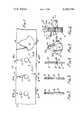
- FIG. 1shows a step-by-step process to form the plates used in this invention
- FIGS. 2, 3 and 4are cross-sections taken at lines 2--2, 3--3 and 4--4, respectively in FIG. 1;
- FIG. 5is a plan view of a plate formed by the process of FIG. 1;
- FIG. 6is a side view of a crankshaft according to the invention.
- crankshaft 10The crankshaft includes a first shaft 11 and a second shaft 12 whose axes 13, 14 are parallel to and offset from one another.
- the counterweight 15comprises a stack of identical plates, in this case example six, which are numbered 16, 17, 18, 19, 20, and 20a. Because they are all identical, only plate 16 will be described in detail. As best shown in FIGS. 4 and 5, it comprises a flat plate with a first and a second side 21, 22.
- First and second shaft mounting holes 23, 24are formed which extend between the two sides.
- a pair of bosses 25, 26On the other side there are formed a pair of depressions 27, 28.
- Theseare formed by punching operations as will later be described. They are preferably made circular.
- bosses 25 and 26preferably have boundary walls 29, 30 which are circular and are also substantially cylindrical. They will be made as close to cylindrical as possible.
- the depressionshave boundary walls 31, 32 which are circular and substantially cylindrical, departing from a pure cylinder only by the amount necessary to enable the part to be separated from the die which forms it.
- the relative dimensions of the boundary walls of the bosses and of the depressionsare such that the bosses make a tight fit (at least a net fit) in the depressions of the neighboring plate.
- a pressed interference fitis to be preferred, but a net fit is also useful.
- FIG. 1there is shown a convenient process for forming the plates. It starts with a metal sheet 35 which may be a strip so that the plates can be made in progressive dies.
- the metal sheethas an index hole 36 formed in an upper part 37 of the sheet which will not form part of the plate when it is completed.
- the index hole and the first and second holes 23, 24are punched.
- the stripis then moved to second station 39, where the index hole is used to locate the first and second holes, and then their walls are sized or burnished as appropriate.
- the stripproceeds to third station 40, where again the work is located by means of the index hole.
- the depressions and bossesare formed by a die-punching stamping operation.
- the stripis moved to the fourth station 41 where a blanking die (not shown) punches a completed plate out from the sheet, leaving a void 42.
- the completed plateis shown in FIG. 5.
- the stack of platesis assembled and placed together. Either at the same time or later the cylindrical portions of the two shafts are pressed into the respective holes.
- the shaftsshould make at least a net fit, and preferably will make an interference fit, whereby the entire device is optimally held together.
- the shaftscould be appropriately shouldered and headed to hold the counterweight together, but the interference fit is sufficient and less expensive.
- the rotational angular alignment of the platesis dependent principally on the interengagement of the bosses and depressions. These are relatively short stubby bosses, and they are too short to bend appreciably. Therefore, the stack is rugged, stiff, and resistive to torque deformation.
- the stackhas been manufactured by inexpensive techniques, without requiring fastening means.
- the material of the platesis carbon steel 1010 drawn hard. In one known device there are five or six plates, each of them being about 0.085 inches thick.
- each depressionis located between the sides of the plate at a spacing from the side from which the boss projects. This leaves a substantial shear web between the two sides, between the bottom of the depression and the base of the boss.
Landscapes
- Engineering & Computer Science (AREA)
- General Engineering & Computer Science (AREA)
- Ocean & Marine Engineering (AREA)
- Mechanical Engineering (AREA)
- Shafts, Cranks, Connecting Bars, And Related Bearings (AREA)
Abstract
Description
Claims (6)
Priority Applications (1)
| Application Number | Priority Date | Filing Date | Title |
|---|---|---|---|
| US06/199,629US4342236A (en) | 1978-09-27 | 1980-10-22 | Crankshaft with laminated counterweight |
Applications Claiming Priority (2)
| Application Number | Priority Date | Filing Date | Title |
|---|---|---|---|
| US94621678A | 1978-09-27 | 1978-09-27 | |
| US06/199,629US4342236A (en) | 1978-09-27 | 1980-10-22 | Crankshaft with laminated counterweight |
Related Parent Applications (1)
| Application Number | Title | Priority Date | Filing Date |
|---|---|---|---|
| US94621678AContinuation | 1978-09-27 | 1978-09-27 |
Publications (1)
| Publication Number | Publication Date |
|---|---|
| US4342236Atrue US4342236A (en) | 1982-08-03 |
Family
ID=26894975
Family Applications (1)
| Application Number | Title | Priority Date | Filing Date |
|---|---|---|---|
| US06/199,629Expired - LifetimeUS4342236A (en) | 1978-09-27 | 1980-10-22 | Crankshaft with laminated counterweight |
Country Status (1)
| Country | Link |
|---|---|
| US (1) | US4342236A (en) |
Cited By (15)
| Publication number | Priority date | Publication date | Assignee | Title |
|---|---|---|---|---|
| FR2573129A1 (en)* | 1984-11-10 | 1986-05-16 | Supervis Ets | CRANKSHAFT, ESPECIALLY FOR SMALL PETROL ENGINES. |
| US4611503A (en)* | 1984-12-24 | 1986-09-16 | Vilter Manufacturing Corporation | Means for removing bearing from crankshaft |
| US5207120A (en)* | 1991-09-03 | 1993-05-04 | General Motors Corporation | Assembled crankshaft |
| US5237892A (en)* | 1992-07-28 | 1993-08-24 | Tecumseh Products Company | Reduced material crankshaft fabrication |
| US5333580A (en)* | 1993-01-29 | 1994-08-02 | Textron Inc. | Starter input shaft |
| US5343618A (en)* | 1991-09-03 | 1994-09-06 | General Motors Corporation | Method of assembling a shaft and apertured member |
| US5899120A (en)* | 1997-05-20 | 1999-05-04 | Panther Machine, Inc. | Crankshaft with laminated counterweight |
| FR2777952A1 (en)* | 1998-03-11 | 1999-10-29 | Tecumseh Products Co | Sealed compressor with electric motor, piston and counterweighted crankshaft |
| US6195888B1 (en) | 1998-03-11 | 2001-03-06 | Tecumseh Products Company | Counterweight for hermetic compressors |
| US6287092B1 (en) | 1998-03-11 | 2001-09-11 | Tecumseh Products Company | Counterweight for hermetic compressors |
| US6418902B1 (en) | 2001-02-08 | 2002-07-16 | Wci Outdoor Products, Inc. | Composite full circle crankshaft counterweight |
| US20050196232A1 (en)* | 2004-03-05 | 2005-09-08 | Mark Manuel | Method and an apparatus for the creation of a tangible item, such as a tool and/or a part, and a tangible item |
| US7021268B1 (en) | 2004-10-29 | 2006-04-04 | Brunswick Corporation | Crankshaft with airflow inducing surfaces |
| US20090308369A1 (en)* | 2008-06-11 | 2009-12-17 | Mavinahally Nagesh S | Laminated Counterweight for Timing Control |
| DE102008029272A1 (en) | 2008-06-19 | 2009-12-24 | Fraunhofer-Gesellschaft zur Förderung der angewandten Forschung e.V. | Crankshaft for reciprocating piston engine i.e. internal-combustion engine, has joint formed between crank cheek and bearing elements, where joint is formed outside transient area of cylindrical lateral contour of bearing elements |
Citations (2)
| Publication number | Priority date | Publication date | Assignee | Title |
|---|---|---|---|---|
| US1261053A (en)* | 1917-06-04 | 1918-04-02 | Frank O'brien | Counterbalance for crank-shafts and method of applying the same. |
| US3590208A (en)* | 1967-11-02 | 1971-06-29 | Licentia Gmbh | Method of aligning and welding laminated sheets for electrical machines |
- 1980
- 1980-10-22USUS06/199,629patent/US4342236A/ennot_activeExpired - Lifetime
Patent Citations (2)
| Publication number | Priority date | Publication date | Assignee | Title |
|---|---|---|---|---|
| US1261053A (en)* | 1917-06-04 | 1918-04-02 | Frank O'brien | Counterbalance for crank-shafts and method of applying the same. |
| US3590208A (en)* | 1967-11-02 | 1971-06-29 | Licentia Gmbh | Method of aligning and welding laminated sheets for electrical machines |
Cited By (19)
| Publication number | Priority date | Publication date | Assignee | Title |
|---|---|---|---|---|
| FR2573129A1 (en)* | 1984-11-10 | 1986-05-16 | Supervis Ets | CRANKSHAFT, ESPECIALLY FOR SMALL PETROL ENGINES. |
| DE3441235A1 (en)* | 1984-11-10 | 1986-05-22 | Etablissement Supervis, Vaduz | CRANKSHAFT, ESPECIALLY FOR SMALL PETROL ENGINES |
| US4611503A (en)* | 1984-12-24 | 1986-09-16 | Vilter Manufacturing Corporation | Means for removing bearing from crankshaft |
| US5207120A (en)* | 1991-09-03 | 1993-05-04 | General Motors Corporation | Assembled crankshaft |
| US5343618A (en)* | 1991-09-03 | 1994-09-06 | General Motors Corporation | Method of assembling a shaft and apertured member |
| US5237892A (en)* | 1992-07-28 | 1993-08-24 | Tecumseh Products Company | Reduced material crankshaft fabrication |
| US5293684A (en)* | 1992-07-28 | 1994-03-15 | Tecumseh Products Company | Reduced material crankshaft fabrication |
| US5333580A (en)* | 1993-01-29 | 1994-08-02 | Textron Inc. | Starter input shaft |
| US5899120A (en)* | 1997-05-20 | 1999-05-04 | Panther Machine, Inc. | Crankshaft with laminated counterweight |
| FR2777952A1 (en)* | 1998-03-11 | 1999-10-29 | Tecumseh Products Co | Sealed compressor with electric motor, piston and counterweighted crankshaft |
| US6195888B1 (en) | 1998-03-11 | 2001-03-06 | Tecumseh Products Company | Counterweight for hermetic compressors |
| US6287092B1 (en) | 1998-03-11 | 2001-09-11 | Tecumseh Products Company | Counterweight for hermetic compressors |
| US6418902B1 (en) | 2001-02-08 | 2002-07-16 | Wci Outdoor Products, Inc. | Composite full circle crankshaft counterweight |
| US20050196232A1 (en)* | 2004-03-05 | 2005-09-08 | Mark Manuel | Method and an apparatus for the creation of a tangible item, such as a tool and/or a part, and a tangible item |
| US20070050966A1 (en)* | 2004-03-05 | 2007-03-08 | Floodcooling Technologies, L.L.C. | Method and an apparatus for the creation of a tangible item, such as a tool and/or a part, and a tangible item |
| US7021268B1 (en) | 2004-10-29 | 2006-04-04 | Brunswick Corporation | Crankshaft with airflow inducing surfaces |
| US20090308369A1 (en)* | 2008-06-11 | 2009-12-17 | Mavinahally Nagesh S | Laminated Counterweight for Timing Control |
| US7975660B2 (en) | 2008-06-11 | 2011-07-12 | Techtronic Outdoor Products Technology Limited | Laminated counterweight for timing control |
| DE102008029272A1 (en) | 2008-06-19 | 2009-12-24 | Fraunhofer-Gesellschaft zur Förderung der angewandten Forschung e.V. | Crankshaft for reciprocating piston engine i.e. internal-combustion engine, has joint formed between crank cheek and bearing elements, where joint is formed outside transient area of cylindrical lateral contour of bearing elements |
Similar Documents
| Publication | Publication Date | Title |
|---|---|---|
| US4342236A (en) | Crankshaft with laminated counterweight | |
| US4635351A (en) | Method and machine for providing alternator pole pieces | |
| US5142178A (en) | Apparatus for aligning stacked laminations of a dynamoelectric machine | |
| EP0338537B1 (en) | Unitized multi-layered gasket and method of making same | |
| US4264663A (en) | Laminated pack comprising a plurality of closely superposed sheets and method and device for forming the pack | |
| US4810454A (en) | Method of manufacturing a gasket having multiple regions of different densities and thicknesses | |
| GB2125321A (en) | Improvements in or relating to methods of manufacturing stacked lamination assemblies for armatures of electric machines | |
| US4356605A (en) | Crankshaft with laminated counterweight | |
| EP0995516A3 (en) | Device for stamping and correct stacking of sheet metal stampings | |
| KR20010042934A (en) | Method for producing a rotor or stator of an electrical machine from sheet metal cuttings | |
| CN113118310A (en) | Stainless steel corrugated plate pressing die | |
| US4809429A (en) | Apparatus for manufacturing laminated assemblies having ridges formed on projections which interlock with recesses of adjacent laminations | |
| JPH1080078A (en) | Laminated core and method of manufacturing the same | |
| US5561999A (en) | Ring forming method | |
| JPH0723652Y2 (en) | Metal laminated gasket | |
| JPH0137212B2 (en) | ||
| JPS56117850A (en) | Working method for leaf plate type hinge by cold forging | |
| JPS6258233B2 (en) | ||
| JPS6174966A (en) | Lamination type plate metal ring gear | |
| SU399272A1 (en) | STAMP FOR CUTTING THE SHEET MATERIAL | |
| JPS5922891Y2 (en) | Original punching die of press die | |
| JPS6340631Y2 (en) | ||
| JPH0711856U (en) | Caulking structure of iron core piece | |
| JPH0137770Y2 (en) | ||
| JPH09201017A (en) | Punching device for steel plate for iron core |
Legal Events
| Date | Code | Title | Description |
|---|---|---|---|
| AS | Assignment | Owner name:FIRST INTERSTATE BANK OF ARIZONA, N.A.,, ARIZONA Free format text:ASSIGNMENT OF ASSIGNORS INTEREST;ASSIGNOR:PISTON POWERED PRODUCTS, INC.;REEL/FRAME:004018/0307 Effective date:19800612 Owner name:FIRST INTERSTATE BANK OF ARIZONA, N.A., P.O. BOX 2 Free format text:ASSIGNMENT OF ASSIGNORS INTEREST.;ASSIGNOR:PISTON POWERED PRODUCTS, INC.;REEL/FRAME:004018/0307 | |
| STCF | Information on status: patent grant | Free format text:PATENTED CASE | |
| AS | Assignment | Owner name:INERTIA DYNAMICS CORP., 7125 WEST GALVESTON, CHAND Free format text:ASSIGNMENT OF ASSIGNORS INTEREST.;ASSIGNOR:PISTON POWERED PRODUCTS;REEL/FRAME:004757/0619 Effective date:19870818 Owner name:INERTIA DYNAMICS CORP., 7125 WEST GALVESTON, CHAND Free format text:ASSIGNMENT OF ASSIGNORS INTEREST.;ASSIGNOR:EVERTS, ROBERT, G.,;REEL/FRAME:004757/0624 Effective date:19870808 | |
| AS | Assignment | Owner name:BANK ONE, N.A., MICHIGAN Free format text:SECURITY INTEREST;ASSIGNOR:MTD SOUTHWEST, INC.;REEL/FRAME:011284/0391 Effective date:20000614 | |
| AS | Assignment | Owner name:MTD SOUTHWEST INC., OHIO Free format text:ASSIGNMENT OF ASSIGNORS INTEREST;ASSIGNOR:RYOBI NORTH AMERICA, INC.;REEL/FRAME:011213/0044 Effective date:20000614 |