US4341351A - Outwardly opening poppet pintle nozzle - Google Patents
Outwardly opening poppet pintle nozzleDownload PDFInfo
- Publication number
- US4341351A US4341351AUS06/155,433US15543380AUS4341351AUS 4341351 AUS4341351 AUS 4341351AUS 15543380 AUS15543380 AUS 15543380AUS 4341351 AUS4341351 AUS 4341351A
- Authority
- US
- United States
- Prior art keywords
- holder body
- valve
- nozzle
- spring seat
- stem
- Prior art date
- Legal status (The legal status is an assumption and is not a legal conclusion. Google has not performed a legal analysis and makes no representation as to the accuracy of the status listed.)
- Expired - Lifetime
Links
- 239000000446fuelSubstances0.000claimsabstractdescription41
- 238000002347injectionMethods0.000claimsabstractdescription18
- 239000007924injectionSubstances0.000claimsabstractdescription18
- 230000000452restraining effectEffects0.000claims3
- 239000012530fluidSubstances0.000claims1
- 238000002485combustion reactionMethods0.000abstractdescription5
- 239000006185dispersionSubstances0.000abstractdescription3
- 230000008901benefitEffects0.000description5
- 238000004519manufacturing processMethods0.000description3
- 230000009471actionEffects0.000description2
- 238000000034methodMethods0.000description2
- 230000004044responseEffects0.000description2
- 230000006978adaptationEffects0.000description1
- 238000005452bendingMethods0.000description1
- 230000006835compressionEffects0.000description1
- 238000007906compressionMethods0.000description1
- 238000010276constructionMethods0.000description1
- 230000000994depressogenic effectEffects0.000description1
- 238000007689inspectionMethods0.000description1
- 238000012986modificationMethods0.000description1
- 230000004048modificationEffects0.000description1
- 230000002093peripheral effectEffects0.000description1
- 230000008439repair processEffects0.000description1
- 230000000717retained effectEffects0.000description1
- 238000000926separation methodMethods0.000description1
Images

Classifications
- F—MECHANICAL ENGINEERING; LIGHTING; HEATING; WEAPONS; BLASTING
- F02—COMBUSTION ENGINES; HOT-GAS OR COMBUSTION-PRODUCT ENGINE PLANTS
- F02M—SUPPLYING COMBUSTION ENGINES IN GENERAL WITH COMBUSTIBLE MIXTURES OR CONSTITUENTS THEREOF
- F02M61/00—Fuel-injectors not provided for in groups F02M39/00 - F02M57/00 or F02M67/00
- F02M61/04—Fuel-injectors not provided for in groups F02M39/00 - F02M57/00 or F02M67/00 having valves, e.g. having a plurality of valves in series
- F02M61/08—Fuel-injectors not provided for in groups F02M39/00 - F02M57/00 or F02M67/00 having valves, e.g. having a plurality of valves in series the valves opening in direction of fuel flow
Definitions
- This inventionrelates to fuel injection nozzles for internal combustion engines and particularly to such nozzles of the outwardly opening poppet pintle type which are particularly adapted for use with high speed engines.
- the inventionis more particularly concerned with an improved nozzle assembly therefor having many advantages in manufacture and use.
- An outwardly opening poppet pintle type fuel injection nozzleis one which has an outwardly opening closure member called the pintle or valve which, when the nozzle is mounted on an engine, is movable toward the combustion chamber of the engine for admitting fuel to the said chamber.
- An example of a fuel injection nozzle of the type to which the present invention pertainsis disclosed in U.S. Pat. No. 2,351,965.
- the valve of the nozzle assemblyis opened by fuel pressure in the direction of the fuel flow through the valve to admit fuel to the engine combustion chamber which occurs each time a charge of fuel is transmitted to the nozzle by a conventional fuel pump.
- the present inventionis intended to overcome these disadvantages by providing a nozzle having a minimal reciprocating mass so that it can be operated effectively at high engine speeds.
- Another advantage of the inventionis that the nozzle is made up of component parts which can be easily machined and finished using conventional manufacturing techniques to provide a free valve action and positive valving without need for extensive lapping, and the nozzle is simple to assemble and disassemble without requiring adjustment after assembly whereby manufacturing costs are reduced to a minimum.
- Another advantage of the inventionis that the nozzle is designed with a variable clearance orifice for the passage and dispersion of the fuel providing optimum operating characteristics.
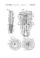
- FIG. 1is a longitudinal view, partially in cross-section, of a nozzle embodying the present invention
- FIG. 2is an enlarged, fragmentary longitudinal view, partially in cross-section of the lower end of the nozzle
- FIG. 3is a cross-sectional view taken generally along the line 3--3 of FIG. 2;
- FIG. 4is a cross-sectional view taken generally along the line 4--4 of FIG. 2;
- FIG. 5is a longitudinal view similar to FIG. 2 showing another embodiment of the invention.
- FIG. 6is a cross-sectional view taken generally along the line 6--6 of FIG. 5;
- FIG. 7is a cross-sectional view taken generally along the line 7--7 of FIG. 5.
- the nozzlecomprises a holder body 10 and a removable nozzle assembly 12 retained therein by a tubular securing nut 14 threadably secured to the exterior of the body 10.
- the nozzleis adapted to be secured to an engine (not shown) by attachment to the securing nut 14.
- the holder body 10has a central fuel duct 16 and an enlarged counterbore 18 at its lower end.
- the upper end of the holder body 10is adapted to be connected by a suitable conduit (not shown) to a fuel pump (also not shown) whereby fuel is supplied to the fuel duct 16.
- a body tip 20Aligned with the holder body 10 is a body tip 20 having a central bore 22 and an enlarged peripheral shoulder 24 at its upper end. Shoulder 24 has the same outer dimensions as the adjacent portion of the holder body 10.
- a shallow counterbore 26 of the body tip 20has the same diameter as and is coaxially aligned with the enlarged counterbore 18 of the holder body 10.
- the lower end of the body tip 20is also counterbored at 28 to form a valve seat 29 for the pintle valve 30.
- the pintle valve 30has a head 32 at its lower end.
- the head 32is rounded at its upper surface to seat on the conical valve seat 29 for fuel cut off.
- the lower end 33 of head 32is enlarged to have a controlled clearance fit in counterbore 28.
- the stem 34 of valve 30is dimensioned so as to provide an annular clearance 36 between it and the central bore 22.
- the pintle valve 30is mounted in the holder body 10 by a cup-shaped combination upper spring seat and valve hanger 40 and an oppositely facing cup-shaped lower spring seat 42.
- the outer diameters of the upper spring seat and valve hanger 40 and lower spring seat 42are the same and are dimensioned to provide a close fit with the inner diameters of counterbore 18 of the holder body 10 and upper counterbore 26 of the body tip 20 whereby the lower spring seat 42 functions to accurately align the counterbores 18 and 26 and whereby the upper spring seat and valve hanger 40 is also accurately aligned with counterbore 28 and valve seat 29.
- the pintle valve 30extends through an eccentrically located hole 44 in the end wall of lower spring seat 42 and a keyhole slot 46 in the end wall of the upper spring seat and valve hanger 40.
- the stem 34 of pintle valve 30has an enlarged bulbous tip 48 at its upper end dimensioned so that it can pass through the eccentric hole 44 and the large portion 45 of the keyhole slot 46 but will engage and seat on the beveled smaller portion 47.
- the pintle valve 30also extends through the center of a spiral compression return spring 50 seated between the upper spring seat and valve hanger 40 and the lower spring seat 42.
- the collar 38which is located on the stem 34 of the pintle valve 30 between the upper spring seat and valve hanger 40 and lower spring seat 42 is intended to prevent the pintle valve 30 from falling into the engine in the event of breakage or separation from the upper spring seat and valve hanger 40.
- the collar 38is dimensioned so that it just fits through the central bore 22 of the body tip 20 and the eccentric hole 44 in the lower spring seat 42.
- valve 30During fuel injection the lower end of the valve 30 is centered hydrodynamically by the fuel flowing through the annular clearance between the valve stem 34 and bore 22 of the body tip 20. The extent of outward movement of the valve 30 is controlled by the engagement of the upper spring seat and valve hanger 40 against the lower spring seat 42.
- a particular advantage of the nozzle construction of my invention as previously mentioned,is that by proper dimensional control, the valve is always aligned properly in the holder body 10, upper spring seat and valve hanger 40, lower spring seat 42 and body tip 20 and when open, is engaged only by the upper spring seat and valve hanger 40. This renders it possible to design the head 32 and counterbore 28 for optimum fuel dispersion characteristics. This arrangement also greatly reduces the size and cost of the nozzle.
- the nozzleis simple to assemble without need for adjustment. To assemble the nozzle, the valve 30 is first placed in the bore 22 of the body tip 20 following which the lower spring seat 42 is slipped over the valve to seated position in the counterbore 26.
- collar 38may pass through hole 44 for assembly but, due to the eccentric relation of collar 38 to central bore 22, it cannot pass into central bore 22 after lower spring seat 42 is seated in counterbore 26.
- the spring 50is then placed over the valve stem 34 and depressed as the upper spring seat and valve hanger 40 is installed.
- This nozzle assembly 12is then inserted into the counterbore 18 of the holder body 10 which coaxially aligns upper spring seat and valve hanger 40 with lower spring seat 42.
- Holder body 10is then clamped into place by the securing nut 14 which engages under the shoulder 24 of the body tip 20. It is to be noted that during assembly no bending or distortion of the valve 30 takes place. By reversing the procedure, the nozzle is just as simple to disassemble for inspection and for repair, reconditioning or replacement of any of the parts.
- FIGS. 5-7A modified embodiment of the invention is shown in FIGS. 5-7.
- the lower spring seat 42ais provided with a keyhole slot instead of the through hole 44 of the embodiment of FIGS. 1-4 which is disposed eccentrically with respect to bore 22 of body tip 20.
- the enlarged portion 44a of the keyhole slothas a sufficient diameter to pass the collar 38 during assembly before the lower spring seat 42a is moved laterally to assume its seated position in the counterbore 26.
- the smaller portion 44b of the keyhole slotis concentric with the bore 22 and is of sufficient size to pass the stem 34 of the valve 30 but not the collar 38.
- the collar 38cannot pass through the smaller portion 44b of the keyhole slot and the larger portion 44a of the keyhole slot will provide unrestricted passage for the flow of fuel past the spring seat. If the collar should move laterally into the enlarged portion 44a of the keyhole slot, the smaller portion 44b will provide for unrestricted flow past the lower spring seat. Thus, pressure in the nozzle during subsequent injection cycles cannot build up high pressures to propel the broken portion of the valve 30 into the cylinder.
- the upper valve hanger designis also modified by forming the valve hanger and the upper spring seat 41 in two parts.
- the keyhole slot 45 through which the enlarged tip 48 passes during assemblyis formed in the valve hanger and functions in the same manner as in the embodiment of FIGS. 1-4 with the upper end of the valve being guided by the valve hanger 40a.
- the upper spring seat 41is an inverted cup-shaped member which is preferably slightly spaced from the annular wall of the enlarged counterbore 18 of the holder body and has a concentric hole 43 which is coaxial with the smaller portion of the keyhole slot 45 so that in the event that the tip 48 of the valve should become disengaged from the hanger during operation, it cannot move laterally a sufficient distance to pass through the larger portion of the keyhole slot 45 since the hole 43 of the spring seat acts as a lateral stop.
- the distance between the upper end of the skirt of the valve hanger 40a and the end of the enlarged counterbore 18 of the holder body 10is limited so that the spring 50 can expand sufficiently to maintain valve hanger 40a and upper spring seat 41, as well as lower spring seat 42a and nozzle body 20, from separating even though the stem 34 of the valve 30 breaks so that the valve 34 cannot fall out of the nozzle.
- the partsare simple to fabricate and can be machined and surface finished to produce free valve action and positive valving without extensive lapping or subsequent adjustment.
Landscapes
- Engineering & Computer Science (AREA)
- Chemical & Material Sciences (AREA)
- Combustion & Propulsion (AREA)
- Mechanical Engineering (AREA)
- General Engineering & Computer Science (AREA)
- Fuel-Injection Apparatus (AREA)
Abstract
Description
Claims (11)
Priority Applications (1)
| Application Number | Priority Date | Filing Date | Title |
|---|---|---|---|
| US06/155,433US4341351A (en) | 1980-06-02 | 1980-06-02 | Outwardly opening poppet pintle nozzle |
Applications Claiming Priority (1)
| Application Number | Priority Date | Filing Date | Title |
|---|---|---|---|
| US06/155,433US4341351A (en) | 1980-06-02 | 1980-06-02 | Outwardly opening poppet pintle nozzle |
Publications (1)
| Publication Number | Publication Date |
|---|---|
| US4341351Atrue US4341351A (en) | 1982-07-27 |
Family
ID=22555407
Family Applications (1)
| Application Number | Title | Priority Date | Filing Date |
|---|---|---|---|
| US06/155,433Expired - LifetimeUS4341351A (en) | 1980-06-02 | 1980-06-02 | Outwardly opening poppet pintle nozzle |
Country Status (1)
| Country | Link |
|---|---|
| US (1) | US4341351A (en) |
Cited By (16)
| Publication number | Priority date | Publication date | Assignee | Title |
|---|---|---|---|---|
| WO1986000668A1 (en)* | 1984-07-03 | 1986-01-30 | Baralaba Pty Ltd | Fuel injector |
| US4597529A (en)* | 1983-07-08 | 1986-07-01 | Charbonnages De France | Self-regulating spray methods and apparatus |
| US4662338A (en)* | 1981-02-17 | 1987-05-05 | Robert Bosch Gmbh | Fuel injection nozzle |
| US5535723A (en)* | 1994-07-29 | 1996-07-16 | Caterpillar Inc. | Electonically-controlled fluid injector having pre-injection pressurizable fluid storage chamber and outwardly-opening direct-operated check |
| WO1998001230A1 (en)* | 1996-07-10 | 1998-01-15 | Outboard Marine Corporation | Nozzle assembly and method of fabrication thereof |
| US5752481A (en)* | 1993-10-18 | 1998-05-19 | Valve Maintenance Corporation | Injection valve assembly for an internal combustion engine |
| US6109549A (en)* | 1999-03-12 | 2000-08-29 | Outboard Marine Corporation | Fuel injector for internal combustion engines and method for making same |
| EP0967386A3 (en)* | 1998-05-29 | 2000-12-06 | Lucas Industries Limited | Fuel injector |
| US6484705B2 (en)* | 2001-02-21 | 2002-11-26 | Delphi Technologies, Inc. | Pintle valve having an internal flow modifier with self-aligning head |
| US6708905B2 (en) | 1999-12-03 | 2004-03-23 | Emissions Control Technology, Llc | Supersonic injector for gaseous fuel engine |
| US20040103877A1 (en)* | 2000-12-01 | 2004-06-03 | Mccoy James J. | Supersonic injector for gaseous fuel engine |
| US20050006898A1 (en)* | 2002-01-24 | 2005-01-13 | Rainer Hardt | Nozzle clamping nut for injection valves and method for producing said nozzle clamping nut |
| US20050082393A1 (en)* | 2003-10-20 | 2005-04-21 | Digicon, Inc. | Direct fuel injector assembly for a compressible natural gas engine |
| US20070095954A1 (en)* | 2005-11-02 | 2007-05-03 | Guy Hoffmann | Solenoid actuated fuel injector having a pressure balanced pintle |
| US7475674B2 (en) | 2002-04-11 | 2009-01-13 | Siemens Aktiengesellschaft | Leakage connection for a fuel injector |
| US11255387B2 (en)* | 2017-02-23 | 2022-02-22 | Magna Powertrain Inc. | Selectable one-way clutch with improved electromagnetic module |
Citations (2)
| Publication number | Priority date | Publication date | Assignee | Title |
|---|---|---|---|---|
| GB530196A (en)* | 1938-07-07 | 1940-12-06 | Bosch Gmbh Robert | Improvements in or relating to fuel injectors for internal combustion engines |
| US2815247A (en)* | 1955-09-21 | 1957-12-03 | Bosch Arma Corp | Fuel injection nozzle |
- 1980
- 1980-06-02USUS06/155,433patent/US4341351A/ennot_activeExpired - Lifetime
Patent Citations (2)
| Publication number | Priority date | Publication date | Assignee | Title |
|---|---|---|---|---|
| GB530196A (en)* | 1938-07-07 | 1940-12-06 | Bosch Gmbh Robert | Improvements in or relating to fuel injectors for internal combustion engines |
| US2815247A (en)* | 1955-09-21 | 1957-12-03 | Bosch Arma Corp | Fuel injection nozzle |
Cited By (22)
| Publication number | Priority date | Publication date | Assignee | Title |
|---|---|---|---|---|
| US4662338A (en)* | 1981-02-17 | 1987-05-05 | Robert Bosch Gmbh | Fuel injection nozzle |
| US4597529A (en)* | 1983-07-08 | 1986-07-01 | Charbonnages De France | Self-regulating spray methods and apparatus |
| WO1986000668A1 (en)* | 1984-07-03 | 1986-01-30 | Baralaba Pty Ltd | Fuel injector |
| US5752481A (en)* | 1993-10-18 | 1998-05-19 | Valve Maintenance Corporation | Injection valve assembly for an internal combustion engine |
| US5535723A (en)* | 1994-07-29 | 1996-07-16 | Caterpillar Inc. | Electonically-controlled fluid injector having pre-injection pressurizable fluid storage chamber and outwardly-opening direct-operated check |
| WO1998001230A1 (en)* | 1996-07-10 | 1998-01-15 | Outboard Marine Corporation | Nozzle assembly and method of fabrication thereof |
| US5752656A (en)* | 1996-07-10 | 1998-05-19 | Outboard Marine Corporation | Nozzle assembly and method of fabrication thereof |
| AU705671B2 (en)* | 1996-07-10 | 1999-05-27 | Outboard Marine Corporation | Nozzle assembly and method of fabrication thereof |
| CN1096300C (en)* | 1996-07-10 | 2002-12-18 | 舷外发动机公司 | Nozzle assembly and method of fabrication thereof |
| US6224001B1 (en)* | 1998-05-29 | 2001-05-01 | Lucas Industries Public Limited Company | Fuel injector |
| EP0967386A3 (en)* | 1998-05-29 | 2000-12-06 | Lucas Industries Limited | Fuel injector |
| US6109549A (en)* | 1999-03-12 | 2000-08-29 | Outboard Marine Corporation | Fuel injector for internal combustion engines and method for making same |
| US6708905B2 (en) | 1999-12-03 | 2004-03-23 | Emissions Control Technology, Llc | Supersonic injector for gaseous fuel engine |
| US20040103877A1 (en)* | 2000-12-01 | 2004-06-03 | Mccoy James J. | Supersonic injector for gaseous fuel engine |
| US6484705B2 (en)* | 2001-02-21 | 2002-11-26 | Delphi Technologies, Inc. | Pintle valve having an internal flow modifier with self-aligning head |
| US20050006898A1 (en)* | 2002-01-24 | 2005-01-13 | Rainer Hardt | Nozzle clamping nut for injection valves and method for producing said nozzle clamping nut |
| US7475829B2 (en)* | 2002-01-24 | 2009-01-13 | Siemens Aktiengesellschaft | Nozzle clamping nut for injection valves and method for producing said nozzle clamping nut |
| US7475674B2 (en) | 2002-04-11 | 2009-01-13 | Siemens Aktiengesellschaft | Leakage connection for a fuel injector |
| US20050082393A1 (en)* | 2003-10-20 | 2005-04-21 | Digicon, Inc. | Direct fuel injector assembly for a compressible natural gas engine |
| US20070095954A1 (en)* | 2005-11-02 | 2007-05-03 | Guy Hoffmann | Solenoid actuated fuel injector having a pressure balanced pintle |
| US7363914B2 (en)* | 2005-11-02 | 2008-04-29 | Delphi Technologies, Inc. | Solenoid actuated fuel injector having a pressure balanced pintle |
| US11255387B2 (en)* | 2017-02-23 | 2022-02-22 | Magna Powertrain Inc. | Selectable one-way clutch with improved electromagnetic module |
Similar Documents
| Publication | Publication Date | Title |
|---|---|---|
| US4341351A (en) | Outwardly opening poppet pintle nozzle | |
| US1952816A (en) | Fuel injector | |
| US5016821A (en) | Fuel injection valve | |
| US4365746A (en) | Swirl injection valve | |
| US4120456A (en) | Fuel injection valve with vortex chamber occupying auxiliary valve | |
| US5154350A (en) | Electromagnetically actuated fuel injection device for an internal combustion engine | |
| US5522550A (en) | Injection nozzle for internal combustion engines | |
| US4467965A (en) | Fuel injection nozzles | |
| US1363470A (en) | Valve construction for fuel-oil motors | |
| US4421278A (en) | Injection valve | |
| JPS605784B2 (en) | fuel injection valve | |
| JPH02211267A (en) | Spray valve | |
| JPH05133297A (en) | Electromagnetic internal combustion engine fuel injection device | |
| US4865002A (en) | Fuel supply system for internal combustion engine | |
| US2154875A (en) | Fuel injector | |
| JPH0626416A (en) | Fuel injection nozzle for pre-injection and main injection | |
| US3528613A (en) | Fuel injector for internal combustion engines | |
| US2172556A (en) | Fuel injector | |
| US5950930A (en) | Fuel injection valve for internal combustion engines | |
| JPH01125559A (en) | Braking release type poppet cover orifice type fuel injection nozzle | |
| CN101852157A (en) | Fuel injectors for internal combustion engines | |
| JPH02186177A (en) | Liquid control valve | |
| CA1072838A (en) | Fuel mixture charge device | |
| US4529165A (en) | Solenoid valve | |
| US2737974A (en) | Aircraft relief valve |
Legal Events
| Date | Code | Title | Description |
|---|---|---|---|
| STCF | Information on status: patent grant | Free format text:PATENTED CASE | |
| AS | Assignment | Owner name:STANADYNE AUTOMOTIVE CORP., A CORP. OF DE, CONNECT Free format text:ASSIGNMENT OF ASSIGNORS INTEREST.;ASSIGNOR:STANADYNE, INC.;REEL/FRAME:005130/0582 Effective date:19890210 | |
| AS | Assignment | Owner name:BANK OF NEW YORK, THE, NEW YORK Free format text:SECURITY INTEREST;ASSIGNOR:STANADYNE AUTOMOTIVE CORP.;REEL/FRAME:007297/0191 Effective date:19950202 Owner name:STANADYNE INC., CONNECTICUT Free format text:RELEASE OF SECURITY INTEREST;ASSIGNOR:CHEMICAL BANK, AS SUCCESSOR IN INTEREST TO MANUFACTURERS HANOVER TRUST COMPANY;REEL/FRAME:007308/0169 Effective date:19950201 | |
| AS | Assignment | Owner name:FIRST NATIONAL BANK OF CHICAGO, THE, NEW YORK Free format text:PATENT SECURITY AGREEMENT;ASSIGNOR:STANADYNE AUTOMOTIVE CORP.;REEL/FRAME:008907/0273 Effective date:19971211 | |
| AS | Assignment | Owner name:STANADYNE CORPORATIN, CONNECTICUT Free format text:RELEASE BY SECURED PARTY;ASSIGNOR:BANK OF NEW YORK, THE;REEL/FRAME:015083/0817 Effective date:20040813 |