US4341153A - Splicing and truss assembly apparatus and methods - Google Patents
Splicing and truss assembly apparatus and methodsDownload PDFInfo
- Publication number
- US4341153A US4341153AUS06/197,543US19754380AUS4341153AUS 4341153 AUS4341153 AUS 4341153AUS 19754380 AUS19754380 AUS 19754380AUS 4341153 AUS4341153 AUS 4341153A
- Authority
- US
- United States
- Prior art keywords
- wood members
- roller means
- wood
- assembly apparatus
- set forth
- Prior art date
- Legal status (The legal status is an assumption and is not a legal conclusion. Google has not performed a legal analysis and makes no representation as to the accuracy of the status listed.)
- Expired - Lifetime
Links
Images


Classifications
- B—PERFORMING OPERATIONS; TRANSPORTING
- B27—WORKING OR PRESERVING WOOD OR SIMILAR MATERIAL; NAILING OR STAPLING MACHINES IN GENERAL
- B27F—DOVETAILED WORK; TENONS; SLOTTING MACHINES FOR WOOD OR SIMILAR MATERIAL; NAILING OR STAPLING MACHINES
- B27F7/00—Nailing or stapling; Nailed or stapled work
- B27F7/15—Machines for driving in nail- plates and spiked fittings
- B27F7/155—Machines for driving in nail- plates and spiked fittings for nail plates
- Y—GENERAL TAGGING OF NEW TECHNOLOGICAL DEVELOPMENTS; GENERAL TAGGING OF CROSS-SECTIONAL TECHNOLOGIES SPANNING OVER SEVERAL SECTIONS OF THE IPC; TECHNICAL SUBJECTS COVERED BY FORMER USPC CROSS-REFERENCE ART COLLECTIONS [XRACs] AND DIGESTS
- Y10—TECHNICAL SUBJECTS COVERED BY FORMER USPC
- Y10S—TECHNICAL SUBJECTS COVERED BY FORMER USPC CROSS-REFERENCE ART COLLECTIONS [XRACs] AND DIGESTS
- Y10S100/00—Presses
- Y10S100/913—Truss presses
- Y—GENERAL TAGGING OF NEW TECHNOLOGICAL DEVELOPMENTS; GENERAL TAGGING OF CROSS-SECTIONAL TECHNOLOGIES SPANNING OVER SEVERAL SECTIONS OF THE IPC; TECHNICAL SUBJECTS COVERED BY FORMER USPC CROSS-REFERENCE ART COLLECTIONS [XRACs] AND DIGESTS
- Y10—TECHNICAL SUBJECTS COVERED BY FORMER USPC
- Y10T—TECHNICAL SUBJECTS COVERED BY FORMER US CLASSIFICATION
- Y10T29/00—Metal working
- Y10T29/49—Method of mechanical manufacture
- Y10T29/49826—Assembling or joining
- Y10T29/49833—Punching, piercing or reaming part by surface of second part
Definitions
- the trussescomprise upper and lower wood chords which may be two by four or other rectangular shapes having end and intermediate wood spacers forming a preliminary truss frame.
- Metal V-webs, formed as sheet metal stampings having end and apex plates with vertical teeth struck therein and reinforcing ribs formed in the intermediate V-legsare pressed in opposed relation on either side of a pair of spaced wooden chords to form an elongated fabricated joist.
- the wood chordsmay be assembled in either flat or on edge relationship to each other utilizing the same V-web toothed metal plate connectors and in practice various chord sizes such as two by three, two by four, two by five and two by six have been employed with V-web connector heights such as 8", 91/4", 103/4" and 16".
- the prior mechanical apparatus employed for assembling such fabricated truss joistscomprised a pair of parallel rails upon which brackets were attached for supporting the chords above and along side each of the rails so that web connectors could first be laid upon the rails with teeth upwardly extending for embedding into the downward faces of the chords and upper webs could be aligned by laying them over the top faces of the chords to form a truss having aligned webs on opposite faces of the chords.
- a pair of clamping deviceswere movable along the rails for selectively clamping aligned pairs of connector portions on opposite chords against the wood embedding the teeth therein.
- Sequential movement of the clamping devices to pairs of connectors and clamping thereofinvolved intermittent step movement and clamping along the length of the joist limiting the speed of assembly to 2,000 linear feet per day with a three man crew compared with speeds in the order of ten times as great on the apparatus disclosed herein.
- Wood "2 ⁇ 4" and other size chords for trusses and other usesare commonly spliced in required lengths with rectangular metal connector plates on either side overlapping abutting ends having teeth struck therein to penetrate the wood and securely join the ends with strength equal to the uncut wood.
- the closest prior art equipment known to applicant for applying such connector platesinvolves placing adjacent ends of the wood members on their sides in abutting relation in a press with connector plates positioned under and over the joint for application through static hydraulic pressing.
- the spliced woodcommonly ranges from 2 ⁇ 3 to 2 ⁇ 8 inches in cross section with rectangular connector plates of appropriate length ranging from 10 to 14 inches and width from 21/2 to 5 inches using 16, 18 and 20 gauge material with struck teeth extending from 1/4" to 1/2".
- An important feature of the present inventionincludes continuous rolling assembly of opposed V-webs on either side of vertically spaced chords passing between spaced parallel powered compression rollers.
- a pair of operators on either side of the assembly machineplace a pair of V-webs onto a lower guide track and against either side of the vertically spaced upper and lower two by four or like chords just ahead of four vertically and laterally spaced opposed compression assembly rollers which continuously drive the upper and lower chords and compress the toothed connector plates of the metal V-webs into embedded assembled engagement with the chords as they pass through the rollers.
- the individual V-websare placed with two lower leg extremities against a lower guide track with the lead leg in abutting engagement with the trailing leg of the next preceding V-web so that in assembled relation a continuous metal truss is formed interrupted however with intermediate spacing for transverse heat ducts or the like which may be readily provided to meet any architectural design requirements.
- Wooden truss frameswith vertical end and intermediate spacers and preassembled and fed between a pair of vertical axis pinch rollers which drive the frame up to the point where the V-webs are manually applied against the sides just before entry between the compression rollers.
- Adjustability of both entry pinch rollers and compression assembly rollersis provided for on-edge or flat orientation of the upper and lower chords which may range in size from 2" ⁇ 3" to 2" ⁇ 6" as well as for vertical spacing which can range over any spacing height required such as 6" to 16".
- the trussis assembled upside down with entry and departure tracks on either side of the compression assembly rollers oriented in slightly sloping relation so as to impose required arching of the respective chord members as they pass through the assembly rollers which, with allowance for springback will be retained in the finished truss joist.
- a rolling techniqueis likewise employed similar to that for applying V-webs in assembling trusses but with certain distinctions. Since splicing takes place at substantially spaced intervals, provision is made for inserting the ends of the 2 ⁇ 4s or like wood members to be spliced between rolling heads without feeding their entire length through the rollers as well as for removing the spliced members following application of the splicing plates without completing longitudinal movement through the rollers.
- the fore and aft pairs of rollersare provided with synchronized drive with the engaging portion of the rear rollers timed slightly ahead of the lead rollers to drive the trailing end into positive abutting engagement before splicing takes place upon passing through the lead rollers.
- the radius of the rollersis dimensioned to accommodate full assembling engagement of the longest connector plates to be processed within the continuous arc segments of the rollers.
- the rear rollersare dimensioned slightly larger than the lead rollers but with equal spacing for pressure engagement in order to further assure positive driven abuttment throughout the rolling application of the connector plates.
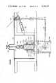
- FIG. 1is a fragmentary side elevation of a preferred embodiment of the truss assembly machine
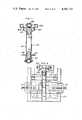
- FIG. 2is an enlarged sectional end elevation taken along the line 2--2 of FIG. 1;
- FIG. 3is a sectional plan view taken along the line 3--3 of FIG. 2;
- FIGS. 4 and 5are enlarged sectional end elevations taken along the lines 4--4 and 5--5 of FIG. 1;
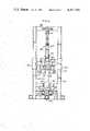
- FIG. 6is a further enlarged fragmentary sectional side elevation taken along the line 6--6 of FIG. 5;
- FIGS. 7, 8 9 and 11are sectional end elevations taken along the lines 7--7, 8--8, 9--9 and 11--11 of FIG. 6;
- FIG. 10is a semi-diagrammatic plan view taken along the line 10--10 of FIG. 6 omitting structural parts for clarity;
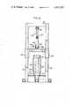
- FIG. 12is an enlarged sectional end elevation taken along the line 12--12 of FIG. 1;
- FIG. 13is a schematic plan view of the chain drive shown in side elevation in FIG. 1;
- FIGS. 14, 15 and 16are fragmentary side elevations of assembled truss joists indicating several size and chord configurations which can be assembled on the illustrated machine.
- FIG. 17is a plan view of the splicing apparatus employed in the present invention.
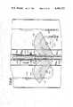
- FIG. 18is a sectional side elevation taken along the line 18--18 of FIG. 17;
- FIG. 19is a sectional end view taken along the line 19--19 of FIG. 18;
- FIG. 20is an enlarged fragmentary view taken along the line 20--20 of FIG. 19;
- FIG. 21is a fragmentary end elevation taken along the line 21--21 of FIG. 17.
- FIG. 22is a perspective view of a truss assembly employing spliced chords and V-web assembly plates applied in accordance with the apparatus and methods of the present invention.
- the major components of the machineinclude a pair of entrance pinch rollers A, a track system B, two pairs of assembly rollers C and a roller drive D.
- the operation of the machineinvolves driving a wood truss frame comprising upper and lower two by four type chords preassembled with wood spacers between pinch rollers A along track system B where toothed metal V-webs are manually placed on either side ahead of the assembly rollers C through which the wood frame with applied V-webs are driven and compressively rolled into assembled engagement.
- a wood truss framecomprising upper and lower chords 20 and 21 joined by end and intermediate spacers 22 is supported in the case of the illustrated configuration on a series of anti-friction rollers 59 along the horizontal surfaces 23 of a pair of track angles 24 welded to an intermediate square tubular track member 25, the upper surface 26 of which serves as a track with projecting spaced rollers 59a for a lower chord oriented on edge as in the optional truss configuration shown in FIG. 15.
- a pair of pinch rollers 27 mounted on vertical shafts 28 driven by chains 29 through sprockets 30are adjustable through upper slides 31 and lower slides 32 positioned by adjustment screws 33 to a spacing for drivingly engaging the upper and lower chords 20 and 21 for whatever chord widths are being assembled.
- the horizontal tube 45branches at section line 8--8 to a pair of spaced tubes 45a which extend beyond roller assembly C to connections with transverse member 48 and sleeves 49 piloted on vertical frame members 50 having transverse support 51 for hanger 52 which is similar to hanger 40 and adjustable through horizontal screw 47 actuated by hand crank 53 so that beam assembly 45, 46 may be simultaneously adjusted at both ends along with guide track 36 suspended by bracket 53 secured to angle 46.
- Lower guide tracks 34are also supported by brackets 54 and upper and lower extensions 36a, 34a of guides 36, 34 are connected at their outer ends by spacer bars 55 which position upper and lower inside rollers 56 and 57 mounted near the ends of the extensions 36a and 34a which with outside upper rollers 58 and lower rollers 59 mounted as shown in FIG. 7 serve to accurately size the spacing of upper and lower chords 20 and 21 immediately before entering between the compression assembly rollers C when assembled as shown with opposing flat sides.
- V-web metal truss elements 60manually placed against either side of the upper and lower chords with the lower leg extremities 61 engaging fixed lower guide tracks 62 are moved into abutting relationship with the trailing legs of the next preceding metal V-web 60a and manually held against the chords until compressively engaged by the respective lower assembly rollers 62 which will progressively compress the integral toothed leading connector plates 63, apex connector plates 64 and trailing connecting plates 65 of the opposed metal V-webs into embedded assembled engagement with the respective upper and lower chords.
- box framegenerally indicated as 66 comprising respectively vertical, longitudinal and transverse frame members 67, 68 and 69 supported on floor legs 70 mounts longitudinal bars 71 and transverse bars 72 on which adjustable journals 73 similar to those illustrated in FIG. 3 are actuated through adjustment screws 74 and vary the position of drive shafts 75 for the lower and upper rollers 62a and 62b to a proper spacing for engaging the respective chords 21 and 20 and metal V-web connector plates 63, 64 and 65.
- rollersare set at a spacing of approximately 1/16" less than the width of the chords to assure compressive drive during engagement between metal connector plates, the additional 0.040" thickness of each of the connector plates being additionally absorbed by compression of the wood and assuring complete penetration of the integral teeth extending at right angles from the connector plates.
- Oppositely rotating drivesare imparted to the drive shaft 75 through universal joint and shaft connections 78 driven by motor 79 through sprocket 80, chain 81, sprockets 82 and couplings 83 as shown in FIG. 1 and the schematic plan view of the drive in FIG. 13.
- Synchronized drivesare imparted to the entrance pinch rollers 27 by power takeoff sprockets 84 at the top of the machine, longitudinal chains 85 and sprockets 86 connected to drive shafts for the pinch rollers 27.
- FIGS. 14, 15 and 16illustrations of typical different truss sizes and chord orientation are shown which may be accommodated through simple adjustments of the machine which can be effected in approximately 10 to 15 minutes.
- standard chord sizes of 2" ⁇ 3", 2" ⁇ 4", 2" ⁇ 5" and 2" ⁇ 6"can be accommodated either on edge or flat with connector V vertical sizes ranging between 6 to 16 inches.
- Currently produced sizes of 8", 91/4", 103/4" and 16"are available and new sizes of 6", 71/4" and 14" are contemplated.
- Metal V-webs 60 manually placed on either side with a leading lower leg plate 63 at the lead end of the trussare held until engaged by the lower rollers 62a whereupon they are driven continuously through the compression rolls into assembled relation.
- Successive V-websare manually placed against the chords and moved forwardly into abutting relationship with the V-legs of the preceding V-webs until such time as an intermediate opening may be programmed, as to accommodate transverse duct passage, whereupon assembly resumes as described.
- Desired camberis automatically imparted to the finished truss by providing a slight rising ramp angle on the assembled joist receiving tracks 23a which cooperate with the sizing rollers to effect an arching of the chords as assembled in an upside down condition relative to their use as joists supported at their ends.
- FIG. 10schematically illustrates in a plan semi-diagrammatic view, with structural parts removed for clear viewing, the arrangement of size control rollers at the upper level.
- the assembly machinecan be run continuously at a speed appropriate to manual placement of the V-webs and provision is made for stopping and reversing the drive motor to remedy any misplacement of one of the webs or to effect any other correction which may be required at an intermediate location in the truss.
- splicing apparatus in accordance with the present inventionincludes a pair of guide rails 101 on track plate 102 supporting a pair of 2 ⁇ 4s 103a and 103b with ends 104, in approximate abutting relation between a pair of retractable guide bars 105 for holding a pair of side connector plates 106 in preassembled position overlapping ends 104 to be spliced.
- guide bars 105are mounted on arms 107 pivotally connected at 108 to base number 109 under relatively light tension of spring 110. Arms 107 may be opened to the dotted line position 107a for loading and unloading purposes by actuation of bellcrank 111 through linkage 112 and 113 responsive to actuation of power cylinder 114 employed for raising cover 115 pivotably mounted at 116 to fixed framework 117 and opened as shown at 118 to provide loading and unloading access.
- rollers 119a and 119bare mounted on a longitudinal square tube 120 vertically positioned by adjustment screws 121 having hand knobs 122 extending over elongated threaded nuts 123 fixed to the top cover 115.
- a pair of 14" diameter semi-cylindrical pressing roller segments 124 mounted on vertical drive shafts 125 on framework members 126 in a leading position and a pair of 141/4" diameter semi-cylindrical drive roller segments 128 mounted on vertical drive shafts 129are respectively driven in synchronized relation by a common drive chain 130, equal drive shaft sprockets 131 and drive motor 132 mounted on apparatus base 133 connected to one of the sprockets 131a as shown in FIG. 19.
- idler sprocket 134 and adjustable take-up sprocket 135complete the system for synchronized drive of respective roller segments 124 and 128 shown in FIG. 17 at the beginning of drive engagement with 2 ⁇ 4s 103a and 103b placed with ends 104 in adjacent abutting relation and connector plates 106 positioned between guide bars 105.
- initial drive engagementfirst takes place by roller segments 128 with 2 ⁇ 4 103b moving it into positive abutting engagement with 2 ⁇ 4 103a due to the slightly advanced timing of roller segments 128 relative to segments 124.
- roller segments 128 and 124 with uniform sprockets 131 and common drive chain 130provide a slightly greater peripheral speed for segments 128 to create a differential speed of driving force on the respective 2 ⁇ 4s thereby additionally forcing their ends together during travel toward the compressing roller segments 124.
- the lateral spacing of compressing rollers segments 124 and auxiliary drive segments 128is such as to equally drivingly engage the sides of the 2 ⁇ 4 with a compressive traction drive. In the case of compressing segments 124 this assures complete penetration of struck teeth of connector plates 106, as best illustrated in FIG. 20, the thickness of such plates being accommodated by compression of the wood fibers during passage between the compressing segments.
- the 22" semi-peripheral circumference of the compression roller segmentsis adequate to engage the 2 ⁇ 4 103a as illustrated in FIG. 17 and to maintain continuous rolling contact with the longest 14" connector plates throughout their travel between segments whereafter the chain drive is stopped to accommodate removal of the spliced 2 ⁇ 4s.
- roller segments 124are illustrated in a compressing position as compared with FIGS. 17, 18 and 21 illustrating the prepositioned condition of the connector plates preparatory to their advance between compressing roller segments.
- Roller segments 124are sufficiently wide to accommodate a range of lumber widths, preferably for "2 ⁇ 3, 2 ⁇ 4, and 2 ⁇ 5" lumber, with a second model of the apparatus having heavier drive shafts and wider roller segments to accommodate "2 ⁇ 6 and 2 ⁇ 8" lumber.
Landscapes
- Engineering & Computer Science (AREA)
- Mechanical Engineering (AREA)
- Life Sciences & Earth Sciences (AREA)
- Forests & Forestry (AREA)
- Absorbent Articles And Supports Therefor (AREA)
- Conveying And Assembling Of Building Elements In Situ (AREA)
- Detergent Compositions (AREA)
- Rod-Shaped Construction Members (AREA)
- Building Environments (AREA)
- Door And Window Frames Mounted To Openings (AREA)
- Chemical And Physical Treatments For Wood And The Like (AREA)
Abstract
Description
Claims (31)
Priority Applications (7)
| Application Number | Priority Date | Filing Date | Title |
|---|---|---|---|
| US06/197,543US4341153A (en) | 1980-01-08 | 1980-10-16 | Splicing and truss assembly apparatus and methods |
| FI810019AFI810019A7 (en) | 1980-01-08 | 1981-01-06 | Method and apparatus for making beam joints. |
| EP81100050AEP0032118B1 (en) | 1980-01-08 | 1981-01-07 | Splicing and truss assembly apparatus |
| NO810037ANO810037L (en) | 1980-01-08 | 1981-01-07 | APPARATUS AND PROCEDURES FOR SKETCHING AND COMPOSITION OF SCIENCES |
| DE8181100050TDE3167881D1 (en) | 1980-01-08 | 1981-01-07 | Splicing and truss assembly apparatus |
| CA000368007ACA1195098A (en) | 1980-01-08 | 1981-01-07 | Splicing and truss assembly apparatus and methods |
| AT81100050TATE10918T1 (en) | 1980-01-08 | 1981-01-07 | DEVICE FOR CONNECTING AND MOUNTING BEAM. |
Applications Claiming Priority (2)
| Application Number | Priority Date | Filing Date | Title |
|---|---|---|---|
| US06/110,366US4287822A (en) | 1980-01-08 | 1980-01-08 | Truss assembly machine |
| US06/197,543US4341153A (en) | 1980-01-08 | 1980-10-16 | Splicing and truss assembly apparatus and methods |
Related Parent Applications (1)
| Application Number | Title | Priority Date | Filing Date |
|---|---|---|---|
| US06/110,366Continuation-In-PartUS4287822A (en) | 1980-01-08 | 1980-01-08 | Truss assembly machine |
Publications (1)
| Publication Number | Publication Date |
|---|---|
| US4341153Atrue US4341153A (en) | 1982-07-27 |
Family
ID=26807959
Family Applications (1)
| Application Number | Title | Priority Date | Filing Date |
|---|---|---|---|
| US06/197,543Expired - LifetimeUS4341153A (en) | 1980-01-08 | 1980-10-16 | Splicing and truss assembly apparatus and methods |
Country Status (7)
| Country | Link |
|---|---|
| US (1) | US4341153A (en) |
| EP (1) | EP0032118B1 (en) |
| AT (1) | ATE10918T1 (en) |
| CA (1) | CA1195098A (en) |
| DE (1) | DE3167881D1 (en) |
| FI (1) | FI810019A7 (en) |
| NO (1) | NO810037L (en) |
Cited By (29)
| Publication number | Priority date | Publication date | Assignee | Title |
|---|---|---|---|---|
| US4514899A (en)* | 1980-12-22 | 1985-05-07 | Raymond Burger | Apparatus with optical projector for assembling a wooden structure |
| US5111861A (en)* | 1988-09-13 | 1992-05-12 | Truswal Systems Corporation | Apparatus for cambering wood trusses |
| US5739508A (en)* | 1994-07-12 | 1998-04-14 | Medrad, Inc. | Closed loop information path for medical fluid delivery systems |
| US6149627A (en)* | 1993-10-28 | 2000-11-21 | Medrad, Inc. | Multi-patient fluid dispensing |
| EP1258262A2 (en) | 1993-10-28 | 2002-11-20 | Medrad, Inc. | Total system for contrast delivery |
| US6612230B1 (en) | 2000-10-10 | 2003-09-02 | Alpine Engineered Products, Inc. | Truss assembly and splicing method and apparatus |
| US20040162488A1 (en)* | 1994-09-21 | 2004-08-19 | Medrad, Inc. | Patient specific dosing contrast delivery systems and methods |
| CN100542792C (en)* | 2008-01-28 | 2009-09-23 | 哈尔滨工业大学 | Building lay wire automatic assembly machine |
| US20100113887A1 (en)* | 2006-12-29 | 2010-05-06 | Medrad, Inc. | Patient-based parameter generation systems for medical injection procedures |
| US7925330B2 (en) | 2004-11-24 | 2011-04-12 | Medrad, Inc. | Devices, systems and methods for determining parameters of one or more phases of an injection procedure |
| US9008759B2 (en) | 2007-07-17 | 2015-04-14 | Bayer Medical Care Inc. | Devices and systems for determination of parameters for a procedure, for estimation of cardiopulmonary function and for fluid delivery |
| US9421330B2 (en) | 2008-11-03 | 2016-08-23 | Bayer Healthcare Llc | Mitigation of contrast-induced nephropathy |
| US9616166B2 (en) | 2004-11-16 | 2017-04-11 | Bayer Healthcare Llc | Systems and methods of determining injection protocols for diagnostic imaging procedures |
| CN106808540A (en)* | 2017-01-25 | 2017-06-09 | 桃江风河智慧竹业有限公司 | A kind of finger connection device of bamboo chip spreading |
| US9700672B2 (en) | 2011-09-21 | 2017-07-11 | Bayer Healthcare Llc | Continuous multi-fluid pump device, drive and actuating system and method |
| US9949704B2 (en) | 2012-05-14 | 2018-04-24 | Bayer Healthcare Llc | Systems and methods for determination of pharmaceutical fluid injection protocols based on x-ray tube voltage |
| US9959389B2 (en) | 2010-06-24 | 2018-05-01 | Bayer Healthcare Llc | Modeling of pharmaceutical propagation and parameter generation for injection protocols |
| US10507319B2 (en) | 2015-01-09 | 2019-12-17 | Bayer Healthcare Llc | Multiple fluid delivery system with multi-use disposable set and features thereof |
| US10898638B2 (en) | 2016-03-03 | 2021-01-26 | Bayer Healthcare Llc | System and method for improved fluid delivery in multi-fluid injector systems |
| US11141535B2 (en) | 2017-08-31 | 2021-10-12 | Bayer Healthcare Llc | Fluid path impedance assessment for improving fluid delivery performance |
| US11278853B2 (en) | 2013-03-13 | 2022-03-22 | Bayer Healthcare Llc | Method for controlling fluid accuracy and backflow compensation |
| US11478581B2 (en) | 2017-08-31 | 2022-10-25 | Bayer Healthcare Llc | Fluid injector system volume compensation system and method |
| US11598664B2 (en) | 2017-08-31 | 2023-03-07 | Bayer Healthcare Llc | Injector pressure calibration system and method |
| US11779702B2 (en) | 2017-08-31 | 2023-10-10 | Bayer Healthcare Llc | Method for dynamic pressure control in a fluid injector system |
| US11786652B2 (en) | 2017-08-31 | 2023-10-17 | Bayer Healthcare Llc | System and method for drive member position and fluid injector system mechanical calibration |
| US12208239B2 (en) | 2018-08-28 | 2025-01-28 | Bayer Healthcare Llc | Fluid injector system, method of preventing fluid backflow, and computer program product |
| US12251544B2 (en) | 2018-04-19 | 2025-03-18 | Bayer Healthcare Llc | System and method for air detection in fluid injector |
| US12263326B2 (en) | 2016-11-14 | 2025-04-01 | Bayer Healthcare Llc | Methods and systems for verifying the contents of a syringe used for medical fluid delivery |
| US12427249B2 (en) | 2018-08-28 | 2025-09-30 | Bayer Healthcare Llc | Fluid injector system with improved ratio performance |
Families Citing this family (4)
| Publication number | Priority date | Publication date | Assignee | Title |
|---|---|---|---|---|
| AT383535B (en)* | 1984-05-16 | 1987-07-10 | Wolf Johann Gmbh Kg | DEVICE FOR CONNECTING BARS BEARING TOGETHER OD. DGL. BY means of NAIL PLATES |
| AT382550B (en)* | 1984-11-26 | 1987-03-10 | Wolf Johann Gmbh Kg | DEVICE FOR CONNECTING JOINING BARS OD. DGL. WITH NAIL PLATES |
| AU650573B2 (en)* | 1992-09-28 | 1994-06-23 | Eric Alexander Brew | Timber connecting apparatus |
| CN106541460B (en)* | 2015-09-16 | 2019-02-19 | 涂樊勇 | A kind of multifunctional solid wood plate joggling apparatus |
Citations (7)
| Publication number | Priority date | Publication date | Assignee | Title |
|---|---|---|---|---|
| US3439607A (en)* | 1966-07-26 | 1969-04-22 | Sanford Arthur C | Method for fabricating trusses in upright position |
| US3785277A (en)* | 1972-07-26 | 1974-01-15 | Truswal Syst Inc | Apparatus and method for making trusses |
| US3855917A (en)* | 1973-10-15 | 1974-12-24 | Dayton Aircraft Prod Inc | Truss plate press |
| US3903583A (en)* | 1975-01-31 | 1975-09-09 | James D Adams | Cambering attachment for truss assembly jig |
| US3908259A (en)* | 1975-01-31 | 1975-09-30 | James D Adams | Cambering attachment for truss assembly jig using canted roller press |
| US4089107A (en)* | 1977-03-14 | 1978-05-16 | Sanford Arthur C | Apparatus for fabricating flat trusses |
| US4154164A (en)* | 1978-04-24 | 1979-05-15 | Hammond Daniel B | Wooden truss fabricating jig |
Family Cites Families (3)
| Publication number | Priority date | Publication date | Assignee | Title |
|---|---|---|---|---|
| US3616091A (en)* | 1969-07-31 | 1971-10-26 | Arthur L Troutner | Forming apparatus for 1-beam-type truss joists |
| US3868898A (en)* | 1973-02-14 | 1975-03-04 | Sanford Arthur C | Rolling truss joint connector plates |
| US4063498A (en)* | 1975-09-17 | 1977-12-20 | Edward Hines Lumber Company | Truss fabricating machine |
- 1980
- 1980-10-16USUS06/197,543patent/US4341153A/ennot_activeExpired - Lifetime
- 1981
- 1981-01-06FIFI810019Apatent/FI810019A7/ennot_activeApplication Discontinuation
- 1981-01-07ATAT81100050Tpatent/ATE10918T1/ennot_activeIP Right Cessation
- 1981-01-07NONO810037Apatent/NO810037L/enunknown
- 1981-01-07EPEP81100050Apatent/EP0032118B1/ennot_activeExpired
- 1981-01-07DEDE8181100050Tpatent/DE3167881D1/ennot_activeExpired
- 1981-01-07CACA000368007Apatent/CA1195098A/ennot_activeExpired
Patent Citations (7)
| Publication number | Priority date | Publication date | Assignee | Title |
|---|---|---|---|---|
| US3439607A (en)* | 1966-07-26 | 1969-04-22 | Sanford Arthur C | Method for fabricating trusses in upright position |
| US3785277A (en)* | 1972-07-26 | 1974-01-15 | Truswal Syst Inc | Apparatus and method for making trusses |
| US3855917A (en)* | 1973-10-15 | 1974-12-24 | Dayton Aircraft Prod Inc | Truss plate press |
| US3903583A (en)* | 1975-01-31 | 1975-09-09 | James D Adams | Cambering attachment for truss assembly jig |
| US3908259A (en)* | 1975-01-31 | 1975-09-30 | James D Adams | Cambering attachment for truss assembly jig using canted roller press |
| US4089107A (en)* | 1977-03-14 | 1978-05-16 | Sanford Arthur C | Apparatus for fabricating flat trusses |
| US4154164A (en)* | 1978-04-24 | 1979-05-15 | Hammond Daniel B | Wooden truss fabricating jig |
Cited By (47)
| Publication number | Priority date | Publication date | Assignee | Title |
|---|---|---|---|---|
| US4514899A (en)* | 1980-12-22 | 1985-05-07 | Raymond Burger | Apparatus with optical projector for assembling a wooden structure |
| US5111861A (en)* | 1988-09-13 | 1992-05-12 | Truswal Systems Corporation | Apparatus for cambering wood trusses |
| US20040199075A1 (en)* | 1993-10-28 | 2004-10-07 | Medrad, Inc. | Total system for contrast delivery |
| US6149627A (en)* | 1993-10-28 | 2000-11-21 | Medrad, Inc. | Multi-patient fluid dispensing |
| US6306117B1 (en) | 1993-10-28 | 2001-10-23 | Medrad, Inc. | Multi-patient fluid dispensing |
| EP1258262A2 (en) | 1993-10-28 | 2002-11-20 | Medrad, Inc. | Total system for contrast delivery |
| US6901283B2 (en) | 1993-10-28 | 2005-05-31 | Medrad, Inc. | Adjusting a condition of a fluid medium to produce an image of a patient |
| US7427281B2 (en) | 1993-10-28 | 2008-09-23 | Medrad, Inc. | Method of delivering fluid mixtures to multiple patients |
| US5920054A (en)* | 1994-07-12 | 1999-07-06 | Medrad, Inc. | Closed loop information path for medical fluid delivery systems |
| US5739508A (en)* | 1994-07-12 | 1998-04-14 | Medrad, Inc. | Closed loop information path for medical fluid delivery systems |
| US20040162488A1 (en)* | 1994-09-21 | 2004-08-19 | Medrad, Inc. | Patient specific dosing contrast delivery systems and methods |
| US7313431B2 (en) | 1994-09-21 | 2007-12-25 | Medrad, Inc. | System and method for inflating a balloon catheter and delivering fluid media to a patient |
| US20080045834A1 (en)* | 1994-09-21 | 2008-02-21 | Medrad, Inc. | System and method for delivering fluids to a balloon catheter |
| US6612230B1 (en) | 2000-10-10 | 2003-09-02 | Alpine Engineered Products, Inc. | Truss assembly and splicing method and apparatus |
| US9616166B2 (en) | 2004-11-16 | 2017-04-11 | Bayer Healthcare Llc | Systems and methods of determining injection protocols for diagnostic imaging procedures |
| US10166326B2 (en) | 2004-11-24 | 2019-01-01 | Bayer Healthcare Llc | Devices, systems and methods for determining parameters of one or more phases of an injection procedure |
| US7925330B2 (en) | 2004-11-24 | 2011-04-12 | Medrad, Inc. | Devices, systems and methods for determining parameters of one or more phases of an injection procedure |
| US9238099B2 (en) | 2004-11-24 | 2016-01-19 | Bayer Healthcare Llc | System and apparatus for modeling pressures generated during an injection procedure |
| US9950107B2 (en) | 2004-11-24 | 2018-04-24 | Bayer Healthcare Llc | Systems and methods for managing workflow for injection procedures |
| US9302044B2 (en) | 2006-12-29 | 2016-04-05 | Bayer Healthcare Llc | Patient-based parameter generation systems for medical injection procedures |
| US20100113887A1 (en)* | 2006-12-29 | 2010-05-06 | Medrad, Inc. | Patient-based parameter generation systems for medical injection procedures |
| US10463782B2 (en) | 2006-12-29 | 2019-11-05 | Bayer Healthcare Llc | Patient-based parameter generation systems for medical injection procedures |
| US9008759B2 (en) | 2007-07-17 | 2015-04-14 | Bayer Medical Care Inc. | Devices and systems for determination of parameters for a procedure, for estimation of cardiopulmonary function and for fluid delivery |
| CN100542792C (en)* | 2008-01-28 | 2009-09-23 | 哈尔滨工业大学 | Building lay wire automatic assembly machine |
| US9421330B2 (en) | 2008-11-03 | 2016-08-23 | Bayer Healthcare Llc | Mitigation of contrast-induced nephropathy |
| US9959389B2 (en) | 2010-06-24 | 2018-05-01 | Bayer Healthcare Llc | Modeling of pharmaceutical propagation and parameter generation for injection protocols |
| US9700672B2 (en) | 2011-09-21 | 2017-07-11 | Bayer Healthcare Llc | Continuous multi-fluid pump device, drive and actuating system and method |
| US11191501B2 (en) | 2012-05-14 | 2021-12-07 | Bayer Healthcare Llc | Systems and methods for determination of pharmaceutical fluid injection protocols based on x-ray tube voltage |
| US9949704B2 (en) | 2012-05-14 | 2018-04-24 | Bayer Healthcare Llc | Systems and methods for determination of pharmaceutical fluid injection protocols based on x-ray tube voltage |
| US11278853B2 (en) | 2013-03-13 | 2022-03-22 | Bayer Healthcare Llc | Method for controlling fluid accuracy and backflow compensation |
| US10507319B2 (en) | 2015-01-09 | 2019-12-17 | Bayer Healthcare Llc | Multiple fluid delivery system with multi-use disposable set and features thereof |
| US12201802B2 (en) | 2015-01-09 | 2025-01-21 | Bayer Healthcare Llc | Multiple fluid delivery system with multi-use disposable set and features thereof |
| US11491318B2 (en) | 2015-01-09 | 2022-11-08 | Bayer Healthcare Llc | Multiple fluid delivery system with multi-use disposable set and features thereof |
| US11672902B2 (en) | 2016-03-03 | 2023-06-13 | Bayer Healthcare Llc | System and method for improved fluid delivery in multi-fluid injector systems |
| US10898638B2 (en) | 2016-03-03 | 2021-01-26 | Bayer Healthcare Llc | System and method for improved fluid delivery in multi-fluid injector systems |
| US12263326B2 (en) | 2016-11-14 | 2025-04-01 | Bayer Healthcare Llc | Methods and systems for verifying the contents of a syringe used for medical fluid delivery |
| CN106808540A (en)* | 2017-01-25 | 2017-06-09 | 桃江风河智慧竹业有限公司 | A kind of finger connection device of bamboo chip spreading |
| US11779702B2 (en) | 2017-08-31 | 2023-10-10 | Bayer Healthcare Llc | Method for dynamic pressure control in a fluid injector system |
| US11598664B2 (en) | 2017-08-31 | 2023-03-07 | Bayer Healthcare Llc | Injector pressure calibration system and method |
| US11786652B2 (en) | 2017-08-31 | 2023-10-17 | Bayer Healthcare Llc | System and method for drive member position and fluid injector system mechanical calibration |
| US11826553B2 (en) | 2017-08-31 | 2023-11-28 | Bayer Healthcare Llc | Fluid path impedance assessment for improving fluid delivery performance |
| US11478581B2 (en) | 2017-08-31 | 2022-10-25 | Bayer Healthcare Llc | Fluid injector system volume compensation system and method |
| US12214155B2 (en) | 2017-08-31 | 2025-02-04 | Bayer Healthcare Llc | Fluid injector system volume compensation system and method |
| US11141535B2 (en) | 2017-08-31 | 2021-10-12 | Bayer Healthcare Llc | Fluid path impedance assessment for improving fluid delivery performance |
| US12251544B2 (en) | 2018-04-19 | 2025-03-18 | Bayer Healthcare Llc | System and method for air detection in fluid injector |
| US12208239B2 (en) | 2018-08-28 | 2025-01-28 | Bayer Healthcare Llc | Fluid injector system, method of preventing fluid backflow, and computer program product |
| US12427249B2 (en) | 2018-08-28 | 2025-09-30 | Bayer Healthcare Llc | Fluid injector system with improved ratio performance |
Also Published As
| Publication number | Publication date |
|---|---|
| CA1195098A (en) | 1985-10-15 |
| EP0032118B1 (en) | 1984-12-27 |
| NO810037L (en) | 1981-07-09 |
| ATE10918T1 (en) | 1985-01-15 |
| FI810019L (en) | 1981-07-09 |
| EP0032118A2 (en) | 1981-07-15 |
| DE3167881D1 (en) | 1985-02-07 |
| EP0032118A3 (en) | 1982-02-03 |
| FI810019A7 (en) | 1981-07-09 |
Similar Documents
| Publication | Publication Date | Title |
|---|---|---|
| US4341153A (en) | Splicing and truss assembly apparatus and methods | |
| CN107127577B (en) | Rolling welding equipment | |
| DE69710099T2 (en) | DEVICE AND METHOD FOR THE AUTOMATED APPLICATION OF A SPACER | |
| CN211388427U (en) | H-shaped steel assembling machine | |
| DE3404006A1 (en) | DEVICE FOR APPLYING AN ADHESIVE STRING OF PLASTIC TO A GLASS PANEL | |
| DE3726274A1 (en) | DEVICE FOR APPLYING FLEXIBLE SPACERS | |
| DE3610551A1 (en) | DEVICE FOR PRODUCING BENEFITS MADE FROM PLASTIC FILM LINES | |
| US5111861A (en) | Apparatus for cambering wood trusses | |
| US4005520A (en) | Frame structure fabricating system | |
| DE2101116C3 (en) | Butt splicing device for butt-to-butt joining of webs | |
| DE1906575A1 (en) | Device on wrapping machines | |
| US3066722A (en) | Board making apparatus | |
| DE2416472B2 (en) | Device for wrapping a fiberglass tube with a film | |
| DE2339518C2 (en) | Device for producing tubular container bodies from a blank | |
| US4089107A (en) | Apparatus for fabricating flat trusses | |
| US4287822A (en) | Truss assembly machine | |
| US5148694A (en) | Sheet metal forming apparatus | |
| US3291360A (en) | Machine for the manufacture of beams and the like | |
| US3868898A (en) | Rolling truss joint connector plates | |
| US4154164A (en) | Wooden truss fabricating jig | |
| US4257150A (en) | Apparatus for assembling wall modules from a pair of stretched sheets of metal laterally spaced apart by a skeletal frame | |
| CN109201885B (en) | Purlin end punching and shaping device | |
| CN110777498A (en) | Gauze bandage elasticizer | |
| US3524785A (en) | Apparatus for jointing timber sections | |
| DE2801904A1 (en) | DEVICE FOR PRODUCING WOOD CONSTRUCTIONS |
Legal Events
| Date | Code | Title | Description |
|---|---|---|---|
| AS | Assignment | Owner name:TRUSWAL SYSTEMS CORPORATION, A CORP. OF MICH. Free format text:ASSIGNMENT OF ASSIGNORS INTEREST.;ASSIGNOR:BOWSER DONALD M.;REEL/FRAME:003862/0660 Effective date:19810601 | |
| STCF | Information on status: patent grant | Free format text:PATENTED CASE | |
| AS | Assignment | Owner name:HOUSEHOLD COMMERCIAL FINANCIAL SERVICES, INC., 270 Free format text:SECURITY INTEREST;ASSIGNOR:TRUSWAL SYSTEMS CORPORATION;REEL/FRAME:004876/0492 | |
| AS | Assignment | Owner name:ITW TRUSWAL CORPORATION, 8925 STERLING STREET, IRV Free format text:ASSIGNMENT OF ASSIGNORS INTEREST.;ASSIGNOR:TRUSWAL SYSTEMS CORPORATION;REEL/FRAME:004860/0503 Effective date:19880217 Owner name:TRUSWAL SYSTEMS CORPORATION, 8925 STERLING STREET, Free format text:ASSIGNMENT OF ASSIGNORS INTEREST.;ASSIGNOR:ITW TRUSWAL CORPORATION;REEL/FRAME:004860/0507 Effective date:19880217 Owner name:ITW TRUSWAL CORPORATION, A CORP. OF DE, TEXAS Free format text:ASSIGNMENT OF ASSIGNORS INTEREST;ASSIGNOR:TRUSWAL SYSTEMS CORPORATION;REEL/FRAME:004860/0503 Effective date:19880217 Owner name:TRUSWAL SYSTEMS CORPORATION, A CORP. OF DE, TEXAS Free format text:ASSIGNMENT OF ASSIGNORS INTEREST;ASSIGNOR:ITW TRUSWAL CORPORATION;REEL/FRAME:004860/0507 Effective date:19880217 | |
| AS | Assignment | Owner name:HOUSEHOLD COMMERCIAL FINANCIAL SERVICES, INC., 270 Free format text:SECURITY INTEREST;ASSIGNOR:TRUSWAL SYSTEMS CORPORATION, (A DE. CORP.);REEL/FRAME:004889/0168 Effective date:19880217 Owner name:HOUSEHOLD COMMERCIAL FINANCIAL SERVICES, INC., ILL Free format text:SECURITY INTEREST;ASSIGNOR:TRUSWAL SYSTEMS CORPORATION, (A DE. CORP.);REEL/FRAME:004889/0168 Effective date:19880217 | |
| AS | Assignment | Owner name:PROVIDENT BANK, THE, OHIO Free format text:ASSIGNMENT OF ASSIGNORS INTEREST;ASSIGNOR:TRUSWAL SYSTEMS CORPORATION;REEL/FRAME:008296/0960 Effective date:19961213 |