US4339874A - Method of making a wedge-shaped permanent magnet rotor assembly - Google Patents
Method of making a wedge-shaped permanent magnet rotor assemblyDownload PDFInfo
- Publication number
- US4339874A US4339874AUS06/214,357US21435780AUS4339874AUS 4339874 AUS4339874 AUS 4339874AUS 21435780 AUS21435780 AUS 21435780AUS 4339874 AUS4339874 AUS 4339874A
- Authority
- US
- United States
- Prior art keywords
- wedge
- magnets
- rotor
- outwardly converging
- shaped
- Prior art date
- Legal status (The legal status is an assumption and is not a legal conclusion. Google has not performed a legal analysis and makes no representation as to the accuracy of the status listed.)
- Expired - Lifetime
Links
Images

Classifications
- H—ELECTRICITY
- H02—GENERATION; CONVERSION OR DISTRIBUTION OF ELECTRIC POWER
- H02K—DYNAMO-ELECTRIC MACHINES
- H02K1/00—Details of the magnetic circuit
- H02K1/06—Details of the magnetic circuit characterised by the shape, form or construction
- H02K1/22—Rotating parts of the magnetic circuit
- H02K1/27—Rotor cores with permanent magnets
- H02K1/2706—Inner rotors
- H02K1/272—Inner rotors the magnetisation axis of the magnets being perpendicular to the rotor axis
- H02K1/274—Inner rotors the magnetisation axis of the magnets being perpendicular to the rotor axis the rotor consisting of two or more circumferentially positioned magnets
- H02K1/2753—Inner rotors the magnetisation axis of the magnets being perpendicular to the rotor axis the rotor consisting of two or more circumferentially positioned magnets the rotor consisting of magnets or groups of magnets arranged with alternating polarity
- H02K1/278—Surface mounted magnets; Inset magnets
- Y—GENERAL TAGGING OF NEW TECHNOLOGICAL DEVELOPMENTS; GENERAL TAGGING OF CROSS-SECTIONAL TECHNOLOGIES SPANNING OVER SEVERAL SECTIONS OF THE IPC; TECHNICAL SUBJECTS COVERED BY FORMER USPC CROSS-REFERENCE ART COLLECTIONS [XRACs] AND DIGESTS
- Y10—TECHNICAL SUBJECTS COVERED BY FORMER USPC
- Y10T—TECHNICAL SUBJECTS COVERED BY FORMER US CLASSIFICATION
- Y10T29/00—Metal working
- Y10T29/49—Method of mechanical manufacture
- Y10T29/49002—Electrical device making
- Y10T29/49009—Dynamoelectric machine
- Y10T29/49012—Rotor
Definitions
- This inventionrelates to permanent magnet rotors and, more particularly, to wedge-shaped permanent magnets in a rotor assembly for use in magnetic couplings, motors, and generators.
- a permanent magnet generatorgenerally consists of a rotor including an even number of equally spaced, alternating polarity magnets around the radial periphery and a stator which includes a number of windings arranged to obtain magnetic couplings with the rotor poles. Rotation of the rotor causes the flux linkage of the permanent magnets with respect to the stator coils to vary, thus inducing an electromotive force in each of the stator coils.
- the rotor permanent magnetshave been rectangularly shaped and supported against centrifugal load by a hoop shrunk over the rotor's periphery.
- the magnetshave relatively poor tensile stress but fairly good compressive strength so they should be compressively retained.
- the thickness of the magnet retaining hoopwas greatly increased, disproportionate to other parts of the rotor, because self-stress of the hoop was large and little structural capacity remained available to carry the magnets.
- difficultiesarose in uniformly distributing the magnet load into the hoop, and this introduced bending stress concentrations into the hoop.
- reluctance of the magnetic circuitincreased and pole head leakage increased.
- the permanent magnet rotorin accordance with the invention, includes a rotatable hub with a plurality of inwardly converging wedge-shaped support members of magnetic material located around and affixed to the non-magnetic hub and outwardly converging wedge-shaped tangentially magnetized. permanent magnets which are radially located within the support members.
- the rotorcan rotate at a higher tip speed and also achieve better utilization of the magnet's field than the prior art rotors.
- the magnetsare held in place in the support member by their wedge-shape without a thick hoop intervening between the magnets and the stator. Structural retention of magnets is provided by fusion bonding to an internal hub of non-magnetic material and proportioned such that it has little or no effect on the exciting flux.
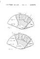
- FIG. 1is a cross-section view of the rotor assembly of the present invention with tangentially magnetized magnets.
- FIG. 2shows a variance of the embodiment of FIG. 1.
- FIG. 3is a cross-section view of the rotor assembly radially magnetized magnets and dampening bars.
- a permanent magnet rotor assembly 10includes a cylindrically shaped hub 12 which is surrounded by and affixed to support members 14.
- the hub 12consists of a non-magnetic material and the support members 14 consist of a ferromagnetic material when tangentially magnetized magnets are used.
- the hub 12 and the support members 14are joined at the junction 16.
- a variety of conventional methodscan be used to join the hub 12 and the support members 14; namely, furnace brazing the two materials together, using a cast bonding technique, diffusion bonding, or bonding by the hot isostatic pressure (HIP) process.
- HIPhot isostatic pressure
- the support members 14have a plurality of generally equally spaced holes 18 disposed near the periphery thereof for reducing the rotor mass so that the rotor 10 can operate at high speeds.
- the holes 18can be of a variety of shapes, the circular shaped holes as shown in FIG. 1 being the easiest to fabricate, whereas, the oblong-shaped holes as shown in FIG. 2 are more difficult to fabricate into the support members 14 but result in lighter weight and a higher tip speed limit.
- the size and location of the holes 18is established with regard to magnetic and structural considerations.
- centrifugal stresses in the rotating rotor 10are a function of radial dimensions, i.e. the centrifugal forces get greater the farther out from the center of the rotor 10. Therefore, in order to reduce the stresses at critical sections (such as at the bonded joint 16) mass is removed from the pole body 14 as near to the periphery of the pole body 14 as magnetic, structural, and manufacturing considerations allow.
- the holes 18permit cooling air flow through the pole body 14 and help to dissipate rotor surface heat caused by eddy currents. Since the stator of a generator or motor is not a smooth surface, but has iron teeth which cause ripple in the air gap flux, eddy currents exist in the rotor surface and cause heating. Excessive temperature is harmful to the structural and magnetic properties of the rotor and magnets.
- the support members 14form a plurality of outwardly converging substantially wedge-shaped slots 20 that are radially disposed about the hub 12.
- the size of the angle formed between the wall of the slots 20 and a plane parallel to a central radius through the magnetis critical and should be slightly less than the angle of friction. This angle is experimentally determined and is the maximum angle at which a locking wedge action is achieved for the material and conditions pertinent to a given design. If the angle is too large the magnets will not remain locked in place after the rotor ceases to rotate and if the angle is too small, lateral crushing forces may cause the magnet to fracture. Therefore, there is a critical range within which the locking angle ⁇ must lie. It has been found that the size of the locking angle ⁇ should be between 2 to 9 degrees, preferably 6 to 8 degrees.
- a plurality of wedge-shaped magnets 22 of substantially the same shape as the slots 20are placed in each of the slots 20.
- the magnets 22are composed of a permanent magnet material.
- the base of the magnet 22can have slightly rounded corners 26 and 28 for easy insertion into the slots 20.
- the magnets 22are shorter in length than the depth of the slot 20 thereby forming a gap 24 between the base of the magnet 22 and the bottom of the slot 20.
- the purpose of the gap 24is to provide a stress relieving radius at the root of the support members 14, to facilitate assembly, and to further cool the rotor 10 permitting cooling air to flow through the rotor assembly.
- a thin hoop 30which is heat shrunk upon the peripheral surface of the support members 14 functions as an electric damper to intercept and diminish the flux harmonics caused by the stator and penetrating into the support members 14 and into the magnet 22. Reflecting eddy currents are produced in the hoop 30, thereby shielding the permanent magnet 22 and the support members 14.
- the hoop 30has a minor structural function, providing a retaining force over the peripheral contact with the magnets 22 and the support members 14. This retaining force is small and merely supplemental to the retaining provided by the hub 12.
- the hoop 30consists of a high strength, non-magnetic material preferably having a low resistivity, such as a beryllium copper alloy.
- Installing the magnets 22 into the rotor assemblyconsists of first sliding the magnets into the base of slot 20 followed by rotating the rotor 10 at its maximum allowable speed. During rotation the magnets 22 move radially outward due to centrifugal force. The magnets 22 lock in place in the slots 20 even after the rotor has ceased rotating due to the compressive forces exerted on the magnets 22 by the walls of the support members 14. The outer portions of the support members 14 and the magnets 22 are then ground to the proper dimensions and the hoop 30 is shrunk onto the periphery, thus completing the assembly.
- FIG. 3shows a rotor assembly with radially magnetized magnets 22.
- the hub 12consists of a magnetic material and the support members 14 consists of a non-magnetic material.
- the gap 24is filled with a closure shim 32.
- the shim 32consists of a ferromagnetic or a permanent magnet material to substantially reduce the reluctance which an air gap created by gap 24 would create. The shim 32 is inserted into the gap 24 after the magnet 22 has been rotated and thereby locked in place as described above.
- the rotor assembly 10 of FIG. 3also has dampening bars 34 which are located near the rotor's periphery and extend through the support members 14. When used with the dampening hoop 30 the bars 34 provide added electrical dampening. Alternatively, the bar 34 can be used without the hoop 30 to intercept and diminish the flux harmonics caused by the stator.
Landscapes
- Engineering & Computer Science (AREA)
- Power Engineering (AREA)
- Permanent Field Magnets Of Synchronous Machinery (AREA)
Abstract
Description
This is a division of application Ser. No. 973,346 filed Dec. 26, 1978, now U.S. Pat. No. 4,242,610.
This invention relates to subject matter disclosed in U.S. patent applications Ser. No. 973,345, filed Dec. 26, 1978, by Jerry Glaser, entitled "Rotor Assembly Having Anchors with Undulating Sides"; Ser. No. 973,344, filed Dec. 26, 1978, by Alexander Silver, entitled "Rotor Assembly Having Rectangularly Shaped Tongues", now U.S. Pat. No. 4,260,921, and Ser. No. 973,343, filed Dec. 26, 1978, by Alexander Silver, Frederick B. McCarty and Lyman R. Burgmeier, entitled "Rotor Assembly with Magnet Cushions", now U.S. Pat. No. 4,302,693, each of which are assigned to the same assignee as this application.
This invention relates to permanent magnet rotors and, more particularly, to wedge-shaped permanent magnets in a rotor assembly for use in magnetic couplings, motors, and generators.
A permanent magnet generator generally consists of a rotor including an even number of equally spaced, alternating polarity magnets around the radial periphery and a stator which includes a number of windings arranged to obtain magnetic couplings with the rotor poles. Rotation of the rotor causes the flux linkage of the permanent magnets with respect to the stator coils to vary, thus inducing an electromotive force in each of the stator coils.
In the prior art, the rotor permanent magnets have been rectangularly shaped and supported against centrifugal load by a hoop shrunk over the rotor's periphery. The magnets have relatively poor tensile stress but fairly good compressive strength so they should be compressively retained. In the case of high speed rotors, the thickness of the magnet retaining hoop was greatly increased, disproportionate to other parts of the rotor, because self-stress of the hoop was large and little structural capacity remained available to carry the magnets. Also, difficulties arose in uniformly distributing the magnet load into the hoop, and this introduced bending stress concentrations into the hoop. Also, as the hoop thickness was increased, reluctance of the magnetic circuit increased and pole head leakage increased.
The permanent magnet rotor, in accordance with the invention, includes a rotatable hub with a plurality of inwardly converging wedge-shaped support members of magnetic material located around and affixed to the non-magnetic hub and outwardly converging wedge-shaped tangentially magnetized. permanent magnets which are radially located within the support members.
Advantages of the present invention are that the rotor can rotate at a higher tip speed and also achieve better utilization of the magnet's field than the prior art rotors. The magnets are held in place in the support member by their wedge-shape without a thick hoop intervening between the magnets and the stator. Structural retention of magnets is provided by fusion bonding to an internal hub of non-magnetic material and proportioned such that it has little or no effect on the exciting flux.
FIG. 1 is a cross-section view of the rotor assembly of the present invention with tangentially magnetized magnets.
FIG. 2 shows a variance of the embodiment of FIG. 1.
FIG. 3 is a cross-section view of the rotor assembly radially magnetized magnets and dampening bars.
Referring now to FIGS. 1 and 2, a permanentmagnet rotor assembly 10 includes a cylindricallyshaped hub 12 which is surrounded by and affixed to supportmembers 14. Thehub 12 consists of a non-magnetic material and thesupport members 14 consist of a ferromagnetic material when tangentially magnetized magnets are used. Thehub 12 and thesupport members 14 are joined at thejunction 16. A variety of conventional methods can be used to join thehub 12 and thesupport members 14; namely, furnace brazing the two materials together, using a cast bonding technique, diffusion bonding, or bonding by the hot isostatic pressure (HIP) process.
Thesupport members 14 have a plurality of generally equally spacedholes 18 disposed near the periphery thereof for reducing the rotor mass so that therotor 10 can operate at high speeds. Theholes 18 can be of a variety of shapes, the circular shaped holes as shown in FIG. 1 being the easiest to fabricate, whereas, the oblong-shaped holes as shown in FIG. 2 are more difficult to fabricate into thesupport members 14 but result in lighter weight and a higher tip speed limit. The size and location of theholes 18 is established with regard to magnetic and structural considerations.
The centrifugal stresses in the rotatingrotor 10 are a function of radial dimensions, i.e. the centrifugal forces get greater the farther out from the center of therotor 10. Therefore, in order to reduce the stresses at critical sections (such as at the bonded joint 16) mass is removed from thepole body 14 as near to the periphery of thepole body 14 as magnetic, structural, and manufacturing considerations allow.
Besides allowing higher tip speed, theholes 18 permit cooling air flow through thepole body 14 and help to dissipate rotor surface heat caused by eddy currents. Since the stator of a generator or motor is not a smooth surface, but has iron teeth which cause ripple in the air gap flux, eddy currents exist in the rotor surface and cause heating. Excessive temperature is harmful to the structural and magnetic properties of the rotor and magnets.
Thesupport members 14 form a plurality of outwardly converging substantially wedge-shaped slots 20 that are radially disposed about thehub 12.
The size of the angle formed between the wall of theslots 20 and a plane parallel to a central radius through the magnet is critical and should be slightly less than the angle of friction. This angle is experimentally determined and is the maximum angle at which a locking wedge action is achieved for the material and conditions pertinent to a given design. If the angle is too large the magnets will not remain locked in place after the rotor ceases to rotate and if the angle is too small, lateral crushing forces may cause the magnet to fracture. Therefore, there is a critical range within which the locking angle θ must lie. It has been found that the size of the locking angle θ should be between 2 to 9 degrees, preferably 6 to 8 degrees.
A plurality of wedge-shaped magnets 22 of substantially the same shape as theslots 20 are placed in each of theslots 20. Themagnets 22 are composed of a permanent magnet material. The base of themagnet 22 can have slightlyrounded corners slots 20.
Themagnets 22 are shorter in length than the depth of theslot 20 thereby forming a gap 24 between the base of themagnet 22 and the bottom of theslot 20. The purpose of the gap 24 is to provide a stress relieving radius at the root of thesupport members 14, to facilitate assembly, and to further cool therotor 10 permitting cooling air to flow through the rotor assembly.
Athin hoop 30 which is heat shrunk upon the peripheral surface of thesupport members 14 functions as an electric damper to intercept and diminish the flux harmonics caused by the stator and penetrating into thesupport members 14 and into themagnet 22. Reflecting eddy currents are produced in thehoop 30, thereby shielding thepermanent magnet 22 and thesupport members 14. Thehoop 30 has a minor structural function, providing a retaining force over the peripheral contact with themagnets 22 and thesupport members 14. This retaining force is small and merely supplemental to the retaining provided by thehub 12. Thehoop 30 consists of a high strength, non-magnetic material preferably having a low resistivity, such as a beryllium copper alloy.
Installing themagnets 22 into the rotor assembly consists of first sliding the magnets into the base ofslot 20 followed by rotating therotor 10 at its maximum allowable speed. During rotation themagnets 22 move radially outward due to centrifugal force. Themagnets 22 lock in place in theslots 20 even after the rotor has ceased rotating due to the compressive forces exerted on themagnets 22 by the walls of thesupport members 14. The outer portions of thesupport members 14 and themagnets 22 are then ground to the proper dimensions and thehoop 30 is shrunk onto the periphery, thus completing the assembly.
FIG. 3 shows a rotor assembly with radiallymagnetized magnets 22. With the radiallymagnetized magnets 22, thehub 12 consists of a magnetic material and thesupport members 14 consists of a non-magnetic material. With the radially magnetizedmagnets 22 of FIG. 4, the gap 24 is filled with a closure shim 32. The shim 32 consists of a ferromagnetic or a permanent magnet material to substantially reduce the reluctance which an air gap created by gap 24 would create. The shim 32 is inserted into the gap 24 after themagnet 22 has been rotated and thereby locked in place as described above.
Therotor assembly 10 of FIG. 3 also has dampeningbars 34 which are located near the rotor's periphery and extend through thesupport members 14. When used with the dampeninghoop 30 thebars 34 provide added electrical dampening. Alternatively, thebar 34 can be used without thehoop 30 to intercept and diminish the flux harmonics caused by the stator.
While specific embodiments of the invention have been illustrated and described, it is to be understood that these embodiments are provided by way of example only and the invention is not to be construed as being limited thereto, but only by the proper scope of the following claims.
Claims (6)
1. A method of forming a rotor for a permanent magnet machine, comprising the steps of:
affixing a plurality of inwardly converging, wedge-shaped support members equally spaced around the periphery of a rotor hub to form a plurality of outwardly converging, wedge-shaped slots therebetween;
inserting a plurality of wedge-shaped permanent magnets having outwardly converging sides, individual magnets disposed in individually outwardly converging wedge-shaped slots between support members; and
rotating the rotor to wedge the outwardly converging permanent magnets into the outwardly converging slots without additional restraint on said magnets.
2. A method of forming a rotor for a permanent magnet machine, comprising the steps of:
affixing a plurality of inwardly converging, wedge-shaped support members equally spaced around the periphery of a rotor hub to form a plurality of outwardly converging, wedge-shaped slots therebetween;
inserting a plurality of wedge-shaped permanent magnets having outwardly converging sides, individual magnets disposed in individually outwardly converging wedge-shaped slots between support members, the sides of said individual magnets forming an angle within the range of 2-9 degrees with a plane parallel to the rotor radius through the center line of said individual magnets; and
rotating the rotor to wedge the outwardly converging permanent magnets into the outwardly converging slots without additional restraint on said magnets.
3. A method of forming a rotor for a permanent magnet machine, comprising the steps of:
affixing a plurality of inwardly converging, wedge-shaped support members equally spaced around the periphery of a rotor hub to form a plurality of outwardly converging, wedge-shaped slots therebetween;
inserting a plurality of wedge-shaped permanent magnets having outwardly converging sides, individual magnets disposed in individually outwardly converging wedge-shaped slots between support members, the sides of said individual magnets forming an angle within the range of 6-8 degrees with a plane parallel to the rotor radius through the center line of said individual magnets; and
rotating the rotor to wedge the outwardly converging permanent magnets into the outwardly converging slots without additional restraint on said magnets.
4. A method of forming a permanent magnet rotor, comprising the steps of:
permanently affixing a plurality of inwardly converging, wedge-shaped ferromagnetic support members equally spaced around the periphery of a non-magnetic rotatable hub to form a plurality of outwardly converging wedge-shaped slots therebetween;
inserting a plurality of wedge-shaped tangentially magnetized permanent magnets having outwardly converging sides, individual magnets disposed in individual outwardly converging wedge-shaped slots between support members; and
without additional restraint on said magnets, rotating the rotor to wedge the outwardly converging permanent magnets in place in the outwardly converging slots without excessive compressive force applied to the sides of said magnets.
5. A method of forming a permanent magnet rotor comprising the steps of:
permanently affixing a plurality of inwardly converging wedge-shaped ferromagnetic support members equally spaced around the periphery of non-magnetic rotatable hub to form a plurality of outwardly converging wedge-shaped slots therebetween;
inserting a plurality of wedge-shaped tangentially magnetized permanent magnets having outwardly converging sides, individual magnets disposed in individual outwardly converging wedge-shaped slots between support members, the sides of said individual magnets forming an angle within the range of 2-9 degrees with a plane parallel to the rotor radius through the center line of said individual magnets; and
without additional restraint on said magnets, rotating the rotor to wedge the outwardly converging permanent magnets in place in the outwardly converging slots without excessive compressive force applied to the sides of said magnets.
6. A method of forming a permanent magnet rotor comprising the steps of:
permanently affixing a plurality of inwardly converging wedge-shaped ferromagnetic support members equally spaced around the periphery of non-magnetic rotatable hub to form a plurality of outwardly converging wedge-shaped slots therebetween;
inserting a plurality of wedge-shaped tangentially magnetized permanent magnets having outwardly converging sides, individual magnets disposed in individual outwardly converging wedge-shaped slots between support members, the sides of said individual magnets forming an angle within the range of 6-8 degrees with a plane parallel to the rotor radius through the center line of said individual magnets; and
without additional restraint on said magnets, rotating the rotor to wedge the outwardly converging permanent magnets in place in the outwardly converging slots without excessive compressive force applied to the sides of said magnets.
Priority Applications (1)
| Application Number | Priority Date | Filing Date | Title |
|---|---|---|---|
| US06/214,357US4339874A (en) | 1978-12-26 | 1980-03-10 | Method of making a wedge-shaped permanent magnet rotor assembly |
Applications Claiming Priority (2)
| Application Number | Priority Date | Filing Date | Title |
|---|---|---|---|
| US05/973,346US4242610A (en) | 1978-12-26 | 1978-12-26 | Wedge-shaped permanent magnet rotor assembly |
| US06/214,357US4339874A (en) | 1978-12-26 | 1980-03-10 | Method of making a wedge-shaped permanent magnet rotor assembly |
Related Parent Applications (1)
| Application Number | Title | Priority Date | Filing Date |
|---|---|---|---|
| US05/973,346DivisionUS4242610A (en) | 1978-12-26 | 1978-12-26 | Wedge-shaped permanent magnet rotor assembly |
Publications (1)
| Publication Number | Publication Date |
|---|---|
| US4339874Atrue US4339874A (en) | 1982-07-20 |
Family
ID=26908912
Family Applications (1)
| Application Number | Title | Priority Date | Filing Date |
|---|---|---|---|
| US06/214,357Expired - LifetimeUS4339874A (en) | 1978-12-26 | 1980-03-10 | Method of making a wedge-shaped permanent magnet rotor assembly |
Country Status (1)
| Country | Link |
|---|---|
| US (1) | US4339874A (en) |
Cited By (85)
| Publication number | Priority date | Publication date | Assignee | Title |
|---|---|---|---|---|
| US4482829A (en)* | 1981-10-08 | 1984-11-13 | Kollmorgen Technologies Corporation | Brushless electric micromotor |
| US4631435A (en)* | 1985-12-18 | 1986-12-23 | The Garrett Corporation | Consequent pole permanent magnet rotor |
| US4638200A (en)* | 1984-05-23 | 1987-01-20 | Precision Mecanique Labinal | High speed permanent magnet rotor |
| US4667123A (en)* | 1985-11-20 | 1987-05-19 | The Garrett Corporation | Two pole permanent magnet rotor construction for toothless stator electrical machine |
| US4843271A (en)* | 1987-12-10 | 1989-06-27 | General Electric Company | Conductive metal inserts in rotor dynamoelectric machine |
| DE3806760A1 (en)* | 1988-03-02 | 1989-09-14 | Heidelberg Motor Gmbh | ELECTRIC MACHINE |
| US5040286A (en)* | 1988-06-08 | 1991-08-20 | General Electric Company | Method for making permanent magnet rotor |
| US5063318A (en)* | 1989-08-25 | 1991-11-05 | Sundstrand Corporation | Preloaded permanent magnet rotor assembly |
| US5144735A (en)* | 1988-06-08 | 1992-09-08 | General Electric Company | Apparatus for assembling a permanent magnet rotor |
| US5168620A (en)* | 1990-11-15 | 1992-12-08 | Westinghouse Electric Corp. | Shunt attachment and method for interfacing current collection systems |
| US5193266A (en)* | 1990-11-15 | 1993-03-16 | Saes Getters Spa | Method of making a brushless electric motor and rotor therefor |
| US5220232A (en)* | 1991-09-03 | 1993-06-15 | Allied Signal Aerospace | Stacked magnet superconducting bearing |
| US5237737A (en)* | 1988-06-08 | 1993-08-24 | General Electric Company | Method of making a permanent magnet rotor |
| WO1993017484A1 (en)* | 1992-02-26 | 1993-09-02 | Magnet-Motor Gesellschaft Für Magnetmotorische Technik Mbh | Electric pump |
| US5298827A (en)* | 1991-11-26 | 1994-03-29 | Mitsubishi Denki Kabushiki Kaisha | Permanent magnet type dynamoelectric machine rotor |
| US5345669A (en)* | 1988-06-08 | 1994-09-13 | General Electric Company | Method of making a permanent magnet rotor |
| US5378953A (en)* | 1992-06-08 | 1995-01-03 | Fanuc Ltd. | Rotor for synchronous motor |
| US5504382A (en)* | 1994-01-24 | 1996-04-02 | Douglass; Michael J. | Field controlled permanent magnet alternator |
| US5563463A (en)* | 1988-06-08 | 1996-10-08 | General Electric Company | Permanent magnet rotor |
| US5568681A (en)* | 1993-08-13 | 1996-10-29 | Asea Brown Boveri Ab | Method for manufacturing a rotor for an electric machine |
| WO1999067871A1 (en)* | 1998-06-25 | 1999-12-29 | Valeo Equipements Electriques Moteur | Rotating machine, such as motor vehicle alternator |
| US6182531B1 (en) | 1998-06-12 | 2001-02-06 | The Boeing Company | Containment ring for flywheel failure |
| US6211589B1 (en) | 1995-06-07 | 2001-04-03 | The Boeing Company | Magnetic systems for energy storage flywheels |
| US6211593B1 (en)* | 1998-10-28 | 2001-04-03 | Okuma Corporation | Synchronous motor with permanent magnet provided on magnetic pole end |
| EP1100175A3 (en)* | 1999-11-10 | 2001-06-27 | Isuzu Motors Limited | Rotor of rotating machine |
| FR2808627A1 (en)* | 2000-05-03 | 2001-11-09 | Leroy Somer | Rotating electrical machine e.g. synchronous motor, has shape of pole pieces and magnets chosen so that difference between the direct axis inductance and quadrature inductance is minimal and teeth do not have constant size |
| US6384504B1 (en)* | 1997-08-27 | 2002-05-07 | Magnet-Motor Gesellschaft Für Magnetmotorische Technik Mbh | Electric machine with a rotor constructed of permanent magnets and magnetic flux guides |
| EP1249919A1 (en)* | 2000-05-03 | 2002-10-16 | Moteurs Leroy-Somer | Rotor of a rotating electrical machine |
| US20020163278A1 (en)* | 2001-04-17 | 2002-11-07 | Moteurs Leroy-Somer | Rotary electric machine having a stator made up of sectors assembled together |
| US20030011265A1 (en)* | 2001-07-10 | 2003-01-16 | Teijin Seiki Co., Ltd. | Permanent magnet motor |
| US6531797B2 (en) | 2001-04-17 | 2003-03-11 | Moteurs Leroy-Somer | Rotary electric machine stator having individual removable coils |
| WO2003084030A1 (en)* | 2002-04-01 | 2003-10-09 | Nissan Motor Co., Ltd. | Rotor body and production method thereof |
| US6661137B2 (en) | 2001-02-20 | 2003-12-09 | Moteurs Leroy-Somer | Drive element such as a driving wheel or a hoisting winch, the element comprising a synchronous motor |
| US6683397B2 (en) | 2001-04-17 | 2004-01-27 | Moteurs Leroy-Somer | Electric machine having at least one magnetic field detector |
| US20040150283A1 (en)* | 2003-01-31 | 2004-08-05 | Calfo Raymond Mark | Trapezoidal shaped magnet flux intensifier motor pole arrangement for improved motor torque density |
| US20040212266A1 (en)* | 2003-04-24 | 2004-10-28 | Helmut Hans | Rotor for an electric motor |
| US20050001503A1 (en)* | 2003-04-24 | 2005-01-06 | Helmut Hans | Rotor for an electric motor |
| US20050025615A1 (en)* | 2003-07-30 | 2005-02-03 | The Boeing Company | High energy containment device and turbine with same |
| US20050046294A1 (en)* | 2003-08-26 | 2005-03-03 | Brent Gordon Rinholm | Permanent magnet motor |
| US6891299B2 (en)* | 2000-05-03 | 2005-05-10 | Moteurs Leroy-Somer | Rotary electric machine having a flux-concentrating rotor and a stator with windings on teeth |
| US20060043814A1 (en)* | 2004-08-25 | 2006-03-02 | Calfo Raymond M | Trapezoidal field pole shape in salient machines |
| US20060097594A1 (en)* | 2003-03-31 | 2006-05-11 | Atef Abou-Akar | Synchronous electrical machine comprising a stator and at least one rotor, and associated control device |
| US20060290222A1 (en)* | 2005-06-28 | 2006-12-28 | Delta Electronics, Inc. | Motor rotor |
| US20070046266A1 (en)* | 2005-08-24 | 2007-03-01 | Honeywell International, Inc. | Excitation controlled synchronous permanent magnet machine |
| US20080256784A1 (en)* | 2007-04-23 | 2008-10-23 | Gregory Paul Cervenka | Methods for making rotors for permanent magnet motors |
| US20100141075A1 (en)* | 2006-12-06 | 2010-06-10 | Honda Motor Co., Ltd | Axial gap motor |
| US20100187933A1 (en)* | 2007-06-26 | 2010-07-29 | Honda Motor Co., Ltd. | Axial gap motor |
| US7893555B2 (en) | 2001-09-13 | 2011-02-22 | Wilic S.Ar.L. | Wind power current generator |
| US7936102B2 (en) | 2005-11-29 | 2011-05-03 | Wilic S.Ar.L | Magnet holder for permanent magnet rotors of rotating machines |
| US7946591B2 (en) | 2005-09-21 | 2011-05-24 | Wilic S.Ar.L. | Combined labyrinth seal and screw-type gasket bearing sealing arrangement |
| JP2011217602A (en)* | 2010-03-31 | 2011-10-27 | Valeo Equipments Electriques Moteur | Flux concentration type synchronous rotating electric machine with permanent magnet |
| US20110316378A1 (en)* | 2010-03-31 | 2011-12-29 | Jean-Claude Matt | Synchronous rotating electrical machine with permanent magnets and flux concentration |
| US8120198B2 (en) | 2008-07-23 | 2012-02-21 | Wilic S.Ar.L. | Wind power turbine |
| US8274170B2 (en) | 2009-04-09 | 2012-09-25 | Willic S.A.R.L. | Wind power turbine including a cable bundle guide device |
| US8272822B2 (en) | 2009-01-30 | 2012-09-25 | Wilic S.Ar.L. | Wind power turbine blade packing and packing method |
| US8310122B2 (en) | 2005-11-29 | 2012-11-13 | Wilic S.A.R.L. | Core plate stack assembly for permanent magnet rotor or rotating machines |
| US8319362B2 (en) | 2008-11-12 | 2012-11-27 | Wilic S.Ar.L. | Wind power turbine with a cooling system |
| US20120326548A1 (en)* | 2010-03-15 | 2012-12-27 | Kabushiki Kaisha Yaskawa Denki | Permanent magnet rotating electrical machine |
| US8358189B2 (en) | 2009-08-07 | 2013-01-22 | Willic S.Ar.L. | Method and apparatus for activating an electric machine, and electric machine |
| US20130049511A1 (en)* | 2010-05-13 | 2013-02-28 | Masashi Nishimura | Permanent magnet embedded rotor |
| US20130049517A1 (en)* | 2011-08-30 | 2013-02-28 | Siemens Industry, Inc. | Induction machine rotor slot and forming method |
| US8410623B2 (en) | 2009-06-10 | 2013-04-02 | Wilic S. AR. L. | Wind power electricity generating system and relative control method |
| US20130162093A1 (en)* | 2010-07-29 | 2013-06-27 | Jean-Claude Matt | Synchronous rotary electric machine having a hybrid-excitation rotor |
| US8492919B2 (en) | 2008-06-19 | 2013-07-23 | Wilic S.Ar.L. | Wind power generator equipped with a cooling system |
| US8541902B2 (en) | 2010-02-04 | 2013-09-24 | Wilic S.Ar.L. | Wind power turbine electric generator cooling system and method and wind power turbine comprising such a cooling system |
| US8618689B2 (en) | 2009-11-23 | 2013-12-31 | Wilic S.Ar.L. | Wind power turbine for generating electric energy |
| US8659867B2 (en) | 2009-04-29 | 2014-02-25 | Wilic S.A.R.L. | Wind power system for generating electric energy |
| US8669685B2 (en) | 2008-11-13 | 2014-03-11 | Wilic S.Ar.L. | Wind power turbine for producing electric energy |
| US20140225469A1 (en)* | 2013-02-13 | 2014-08-14 | Jtekt Corporation | Magnet embedded rotor and method of manufacturing the magnet embedded rotor |
| EP2793366A1 (en)* | 2013-04-16 | 2014-10-22 | Siemens Aktiengesellschaft | Method for producing a single segment rotor with a sleeve device and corresponding rotor |
| US8937397B2 (en) | 2010-03-30 | 2015-01-20 | Wilic S.A.R.L. | Wind power turbine and method of removing a bearing from a wind power turbine |
| US8937398B2 (en) | 2011-03-10 | 2015-01-20 | Wilic S.Ar.L. | Wind turbine rotary electric machine |
| US8957555B2 (en) | 2011-03-10 | 2015-02-17 | Wilic S.Ar.L. | Wind turbine rotary electric machine |
| US8975770B2 (en) | 2010-04-22 | 2015-03-10 | Wilic S.Ar.L. | Wind power turbine electric generator and wind power turbine equipped with an electric generator |
| US9006918B2 (en) | 2011-03-10 | 2015-04-14 | Wilic S.A.R.L. | Wind turbine |
| US20160087496A1 (en)* | 2013-04-16 | 2016-03-24 | Siemens Aktiengesellschaft | Individual-segment rotor having retaining rings |
| US20160141926A1 (en)* | 2013-05-01 | 2016-05-19 | Hitachi Automotive Systems, Ltd. | Rotary Electrical Machine, and Rotor for Rotary Electrical Machine |
| US20170070113A1 (en)* | 2015-09-08 | 2017-03-09 | Lg Electronics Inc. | Rotor and motor including the same |
| CN107546890A (en)* | 2016-06-28 | 2018-01-05 | 特灵国际有限公司 | Motor, method, AC electric systems and the variable speed drive system of harmonic wave shunting |
| US10312783B2 (en) | 2017-05-23 | 2019-06-04 | Ford Global Technologies, Llc | Variable flux bridge for rotor an electric machine |
| US10516305B2 (en) | 2017-05-23 | 2019-12-24 | Ford Global Technologies, Llc | Variable flux bridge for rotor of an electric machine |
| EP3657639A1 (en)* | 2018-11-26 | 2020-05-27 | LG Electronics Inc. | Motor |
| US11005320B2 (en) | 2018-05-04 | 2021-05-11 | Ford Global Technologies, Llc | Variable flux bridge for rotor of an electric machine |
| US11172308B2 (en)* | 2015-08-04 | 2021-11-09 | Curtis E. Graber | Electric motor |
| FR3134931A1 (en)* | 2022-04-22 | 2023-10-27 | Erneo | ROTATING PART OF THE “ROTOR” TYPE WITH SURFACE MAGNETS AND ASSOCIATED ELECTRIC AND/OR MAGNETIC MACHINE. |
Citations (13)
| Publication number | Priority date | Publication date | Assignee | Title |
|---|---|---|---|---|
| US1948854A (en)* | 1932-08-29 | 1934-02-27 | Fairbanks Morse & Co | Magneto electric machine |
| US1979813A (en)* | 1933-10-27 | 1934-11-06 | Fairbanks Morse & Co | Rotor for magnetos |
| US2493102A (en)* | 1946-12-26 | 1950-01-03 | Keefe And Merritt Company O | Rotor for electric machines and method of making the same |
| US2719931A (en)* | 1951-03-17 | 1955-10-04 | Kober William | Permanent magnet field generators |
| US2930916A (en)* | 1957-07-01 | 1960-03-29 | Continental Motors Corp | Generator rotor construction |
| US3072813A (en)* | 1957-10-22 | 1963-01-08 | Philips Corp | Rotor having a plurality of permanent magnets arranged on their periphery |
| US3083311A (en)* | 1956-11-08 | 1963-03-26 | Krasnow Shelley | Converters and circuits for high frequency fluorescent lighting |
| US3671788A (en)* | 1970-11-30 | 1972-06-20 | Gen Lab Associates Inc | Regulatable alternator |
| US3677330A (en)* | 1969-04-24 | 1972-07-18 | Inst Elektroswarki Patona | Method of manufacturing bimetallic rotors employed in electric machines |
| US3858308A (en)* | 1973-06-22 | 1975-01-07 | Bendix Corp | Process for making a rotor assembly |
| US3909647A (en)* | 1973-06-22 | 1975-09-30 | Bendix Corp | Rotor assembly for permanent magnet generator |
| US4117360A (en)* | 1977-04-15 | 1978-09-26 | General Electric Company | Self-supporting amortisseur cage for high-speed synchronous machine solid rotor |
| DE2659650A1 (en) | 1976-12-30 | 1978-11-16 | Siemens Ag | Permanent magnet excited motor - incorporates system for intensive magnet cooling to prevent flux reduction due to high temp. |
- 1980
- 1980-03-10USUS06/214,357patent/US4339874A/ennot_activeExpired - Lifetime
Patent Citations (13)
| Publication number | Priority date | Publication date | Assignee | Title |
|---|---|---|---|---|
| US1948854A (en)* | 1932-08-29 | 1934-02-27 | Fairbanks Morse & Co | Magneto electric machine |
| US1979813A (en)* | 1933-10-27 | 1934-11-06 | Fairbanks Morse & Co | Rotor for magnetos |
| US2493102A (en)* | 1946-12-26 | 1950-01-03 | Keefe And Merritt Company O | Rotor for electric machines and method of making the same |
| US2719931A (en)* | 1951-03-17 | 1955-10-04 | Kober William | Permanent magnet field generators |
| US3083311A (en)* | 1956-11-08 | 1963-03-26 | Krasnow Shelley | Converters and circuits for high frequency fluorescent lighting |
| US2930916A (en)* | 1957-07-01 | 1960-03-29 | Continental Motors Corp | Generator rotor construction |
| US3072813A (en)* | 1957-10-22 | 1963-01-08 | Philips Corp | Rotor having a plurality of permanent magnets arranged on their periphery |
| US3677330A (en)* | 1969-04-24 | 1972-07-18 | Inst Elektroswarki Patona | Method of manufacturing bimetallic rotors employed in electric machines |
| US3671788A (en)* | 1970-11-30 | 1972-06-20 | Gen Lab Associates Inc | Regulatable alternator |
| US3858308A (en)* | 1973-06-22 | 1975-01-07 | Bendix Corp | Process for making a rotor assembly |
| US3909647A (en)* | 1973-06-22 | 1975-09-30 | Bendix Corp | Rotor assembly for permanent magnet generator |
| DE2659650A1 (en) | 1976-12-30 | 1978-11-16 | Siemens Ag | Permanent magnet excited motor - incorporates system for intensive magnet cooling to prevent flux reduction due to high temp. |
| US4117360A (en)* | 1977-04-15 | 1978-09-26 | General Electric Company | Self-supporting amortisseur cage for high-speed synchronous machine solid rotor |
Cited By (122)
| Publication number | Priority date | Publication date | Assignee | Title |
|---|---|---|---|---|
| US4482829A (en)* | 1981-10-08 | 1984-11-13 | Kollmorgen Technologies Corporation | Brushless electric micromotor |
| US4638200A (en)* | 1984-05-23 | 1987-01-20 | Precision Mecanique Labinal | High speed permanent magnet rotor |
| US4667123A (en)* | 1985-11-20 | 1987-05-19 | The Garrett Corporation | Two pole permanent magnet rotor construction for toothless stator electrical machine |
| US4631435A (en)* | 1985-12-18 | 1986-12-23 | The Garrett Corporation | Consequent pole permanent magnet rotor |
| US4843271A (en)* | 1987-12-10 | 1989-06-27 | General Electric Company | Conductive metal inserts in rotor dynamoelectric machine |
| DE3806760A1 (en)* | 1988-03-02 | 1989-09-14 | Heidelberg Motor Gmbh | ELECTRIC MACHINE |
| US5144735A (en)* | 1988-06-08 | 1992-09-08 | General Electric Company | Apparatus for assembling a permanent magnet rotor |
| US5563463A (en)* | 1988-06-08 | 1996-10-08 | General Electric Company | Permanent magnet rotor |
| US5237737A (en)* | 1988-06-08 | 1993-08-24 | General Electric Company | Method of making a permanent magnet rotor |
| US5345669A (en)* | 1988-06-08 | 1994-09-13 | General Electric Company | Method of making a permanent magnet rotor |
| US5040286A (en)* | 1988-06-08 | 1991-08-20 | General Electric Company | Method for making permanent magnet rotor |
| US5063318A (en)* | 1989-08-25 | 1991-11-05 | Sundstrand Corporation | Preloaded permanent magnet rotor assembly |
| US5168620A (en)* | 1990-11-15 | 1992-12-08 | Westinghouse Electric Corp. | Shunt attachment and method for interfacing current collection systems |
| US5193266A (en)* | 1990-11-15 | 1993-03-16 | Saes Getters Spa | Method of making a brushless electric motor and rotor therefor |
| US5220232A (en)* | 1991-09-03 | 1993-06-15 | Allied Signal Aerospace | Stacked magnet superconducting bearing |
| US5298827A (en)* | 1991-11-26 | 1994-03-29 | Mitsubishi Denki Kabushiki Kaisha | Permanent magnet type dynamoelectric machine rotor |
| WO1993017484A1 (en)* | 1992-02-26 | 1993-09-02 | Magnet-Motor Gesellschaft Für Magnetmotorische Technik Mbh | Electric pump |
| US5641276A (en)* | 1992-02-26 | 1997-06-24 | Magnet-Motor Gesellschaft Fur Magnetmotorische Technik Mbh | Electric pump for environmentally hazardous material |
| US5378953A (en)* | 1992-06-08 | 1995-01-03 | Fanuc Ltd. | Rotor for synchronous motor |
| US5568681A (en)* | 1993-08-13 | 1996-10-29 | Asea Brown Boveri Ab | Method for manufacturing a rotor for an electric machine |
| US5504382A (en)* | 1994-01-24 | 1996-04-02 | Douglass; Michael J. | Field controlled permanent magnet alternator |
| US6211589B1 (en) | 1995-06-07 | 2001-04-03 | The Boeing Company | Magnetic systems for energy storage flywheels |
| US6384504B1 (en)* | 1997-08-27 | 2002-05-07 | Magnet-Motor Gesellschaft Für Magnetmotorische Technik Mbh | Electric machine with a rotor constructed of permanent magnets and magnetic flux guides |
| US6182531B1 (en) | 1998-06-12 | 2001-02-06 | The Boeing Company | Containment ring for flywheel failure |
| US6271613B1 (en) | 1998-06-25 | 2001-08-07 | Valeo Equipment Electriques Moteur | Rotating machine, such as motor vehicle alternator |
| WO1999067871A1 (en)* | 1998-06-25 | 1999-12-29 | Valeo Equipements Electriques Moteur | Rotating machine, such as motor vehicle alternator |
| FR2780580A1 (en)* | 1998-06-25 | 1999-12-31 | Valeo Equip Electr Moteur | Magnetic structure for motor vehicle alternator |
| US6211593B1 (en)* | 1998-10-28 | 2001-04-03 | Okuma Corporation | Synchronous motor with permanent magnet provided on magnetic pole end |
| EP1100175A3 (en)* | 1999-11-10 | 2001-06-27 | Isuzu Motors Limited | Rotor of rotating machine |
| US6429566B1 (en) | 1999-11-10 | 2002-08-06 | Isuzu Motors Limited | Rotor of rotating machine |
| FR2808627A1 (en)* | 2000-05-03 | 2001-11-09 | Leroy Somer | Rotating electrical machine e.g. synchronous motor, has shape of pole pieces and magnets chosen so that difference between the direct axis inductance and quadrature inductance is minimal and teeth do not have constant size |
| EP1249919A1 (en)* | 2000-05-03 | 2002-10-16 | Moteurs Leroy-Somer | Rotor of a rotating electrical machine |
| US6891299B2 (en)* | 2000-05-03 | 2005-05-10 | Moteurs Leroy-Somer | Rotary electric machine having a flux-concentrating rotor and a stator with windings on teeth |
| US6661137B2 (en) | 2001-02-20 | 2003-12-09 | Moteurs Leroy-Somer | Drive element such as a driving wheel or a hoisting winch, the element comprising a synchronous motor |
| US20020163278A1 (en)* | 2001-04-17 | 2002-11-07 | Moteurs Leroy-Somer | Rotary electric machine having a stator made up of sectors assembled together |
| US6531797B2 (en) | 2001-04-17 | 2003-03-11 | Moteurs Leroy-Somer | Rotary electric machine stator having individual removable coils |
| US6683397B2 (en) | 2001-04-17 | 2004-01-27 | Moteurs Leroy-Somer | Electric machine having at least one magnetic field detector |
| US6975057B2 (en) | 2001-04-17 | 2005-12-13 | Moteurs Leroy-Somer | Rotary electric machine having a stator made up of sectors assembled together |
| US20030011265A1 (en)* | 2001-07-10 | 2003-01-16 | Teijin Seiki Co., Ltd. | Permanent magnet motor |
| US6906444B2 (en)* | 2001-07-10 | 2005-06-14 | Teijin Seiki Co., Ltd. | Permanent magnet motor |
| US7893555B2 (en) | 2001-09-13 | 2011-02-22 | Wilic S.Ar.L. | Wind power current generator |
| US20040130235A1 (en)* | 2002-04-01 | 2004-07-08 | Takashi Kato | Rotor body and production method thereof |
| US7028386B2 (en) | 2002-04-01 | 2006-04-18 | Nissan Motor Co., Ltd. | Rotor body and production method thereof |
| WO2003084030A1 (en)* | 2002-04-01 | 2003-10-09 | Nissan Motor Co., Ltd. | Rotor body and production method thereof |
| US20040150283A1 (en)* | 2003-01-31 | 2004-08-05 | Calfo Raymond Mark | Trapezoidal shaped magnet flux intensifier motor pole arrangement for improved motor torque density |
| US6879075B2 (en) | 2003-01-31 | 2005-04-12 | Curtiss-Wright Electro-Mechanical Corporation | Trapezoidal shaped magnet flux intensifier motor pole arrangement for improved motor torque density |
| US7388310B2 (en)* | 2003-03-31 | 2008-06-17 | Moteurs Leroy-Somer | Synchronous electrical machine comprising a stator and at least one rotor, and associated control device |
| US20060097594A1 (en)* | 2003-03-31 | 2006-05-11 | Atef Abou-Akar | Synchronous electrical machine comprising a stator and at least one rotor, and associated control device |
| US20050001503A1 (en)* | 2003-04-24 | 2005-01-06 | Helmut Hans | Rotor for an electric motor |
| US20040212266A1 (en)* | 2003-04-24 | 2004-10-28 | Helmut Hans | Rotor for an electric motor |
| US6987342B2 (en) | 2003-04-24 | 2006-01-17 | Minebea Co., Ltd. | Rotor for an electric motor |
| US7196446B2 (en)* | 2003-04-24 | 2007-03-27 | Minebea Co., Ltd. | Rotor for an electric motor |
| US20050025615A1 (en)* | 2003-07-30 | 2005-02-03 | The Boeing Company | High energy containment device and turbine with same |
| US7008173B2 (en) | 2003-07-30 | 2006-03-07 | The Boeing Company | High energy containment device and turbine with same |
| US6984908B2 (en) | 2003-08-26 | 2006-01-10 | Deere & Company | Permanent magnet motor |
| US20050184611A1 (en)* | 2003-08-26 | 2005-08-25 | Deere & Co. | Permanent magnet motor |
| US20050046294A1 (en)* | 2003-08-26 | 2005-03-03 | Brent Gordon Rinholm | Permanent magnet motor |
| US20060043814A1 (en)* | 2004-08-25 | 2006-03-02 | Calfo Raymond M | Trapezoidal field pole shape in salient machines |
| US20060290222A1 (en)* | 2005-06-28 | 2006-12-28 | Delta Electronics, Inc. | Motor rotor |
| US20070046266A1 (en)* | 2005-08-24 | 2007-03-01 | Honeywell International, Inc. | Excitation controlled synchronous permanent magnet machine |
| US7301310B2 (en)* | 2005-08-24 | 2007-11-27 | Honeywell International, Inc. | Excitation controlled synchronous permanent magnet machine |
| US7946591B2 (en) | 2005-09-21 | 2011-05-24 | Wilic S.Ar.L. | Combined labyrinth seal and screw-type gasket bearing sealing arrangement |
| US8310122B2 (en) | 2005-11-29 | 2012-11-13 | Wilic S.A.R.L. | Core plate stack assembly for permanent magnet rotor or rotating machines |
| US7936102B2 (en) | 2005-11-29 | 2011-05-03 | Wilic S.Ar.L | Magnet holder for permanent magnet rotors of rotating machines |
| US20100141075A1 (en)* | 2006-12-06 | 2010-06-10 | Honda Motor Co., Ltd | Axial gap motor |
| US20080256784A1 (en)* | 2007-04-23 | 2008-10-23 | Gregory Paul Cervenka | Methods for making rotors for permanent magnet motors |
| WO2008129328A1 (en) | 2007-04-23 | 2008-10-30 | National Oilwell Varco, L.P. | A rotor for a permanent magnet motor |
| US7673380B2 (en) | 2007-04-23 | 2010-03-09 | Varco I/P, Inc. | Methods for making rotors for permanent magnet motors |
| US20100187933A1 (en)* | 2007-06-26 | 2010-07-29 | Honda Motor Co., Ltd. | Axial gap motor |
| US8283829B2 (en) | 2007-06-26 | 2012-10-09 | Honda Motor Co., Ltd. | Axial gap motor |
| US9312741B2 (en) | 2008-06-19 | 2016-04-12 | Windfin B.V. | Wind power generator equipped with a cooling system |
| US8492919B2 (en) | 2008-06-19 | 2013-07-23 | Wilic S.Ar.L. | Wind power generator equipped with a cooling system |
| US10505419B2 (en) | 2008-06-19 | 2019-12-10 | Windfin B.V. | Wind power generator equipped with a cooling system |
| US8120198B2 (en) | 2008-07-23 | 2012-02-21 | Wilic S.Ar.L. | Wind power turbine |
| US8319362B2 (en) | 2008-11-12 | 2012-11-27 | Wilic S.Ar.L. | Wind power turbine with a cooling system |
| US8669685B2 (en) | 2008-11-13 | 2014-03-11 | Wilic S.Ar.L. | Wind power turbine for producing electric energy |
| US8272822B2 (en) | 2009-01-30 | 2012-09-25 | Wilic S.Ar.L. | Wind power turbine blade packing and packing method |
| US8274170B2 (en) | 2009-04-09 | 2012-09-25 | Willic S.A.R.L. | Wind power turbine including a cable bundle guide device |
| US8659867B2 (en) | 2009-04-29 | 2014-02-25 | Wilic S.A.R.L. | Wind power system for generating electric energy |
| US8410623B2 (en) | 2009-06-10 | 2013-04-02 | Wilic S. AR. L. | Wind power electricity generating system and relative control method |
| US8810347B2 (en) | 2009-08-07 | 2014-08-19 | Wilic S.Ar.L | Method and apparatus for activating an electric machine, and electric machine |
| US8358189B2 (en) | 2009-08-07 | 2013-01-22 | Willic S.Ar.L. | Method and apparatus for activating an electric machine, and electric machine |
| US8618689B2 (en) | 2009-11-23 | 2013-12-31 | Wilic S.Ar.L. | Wind power turbine for generating electric energy |
| US8541902B2 (en) | 2010-02-04 | 2013-09-24 | Wilic S.Ar.L. | Wind power turbine electric generator cooling system and method and wind power turbine comprising such a cooling system |
| US20120326548A1 (en)* | 2010-03-15 | 2012-12-27 | Kabushiki Kaisha Yaskawa Denki | Permanent magnet rotating electrical machine |
| US9219389B2 (en)* | 2010-03-15 | 2015-12-22 | Kabushiki Kaisha Yaskawa Denki | Permanent magnet rotating electrical machine |
| US8937397B2 (en) | 2010-03-30 | 2015-01-20 | Wilic S.A.R.L. | Wind power turbine and method of removing a bearing from a wind power turbine |
| US8669682B2 (en)* | 2010-03-31 | 2014-03-11 | Valeo Equipements Electriques Moteur | Synchronous rotating electrical machine with permanent magnets and flux concentration |
| EP2372873A3 (en)* | 2010-03-31 | 2016-10-05 | Valeo Equipements Electriques Moteur | Synchronous rotating electric machine with permanent magnets and flux concentration |
| US20110316378A1 (en)* | 2010-03-31 | 2011-12-29 | Jean-Claude Matt | Synchronous rotating electrical machine with permanent magnets and flux concentration |
| JP2011217602A (en)* | 2010-03-31 | 2011-10-27 | Valeo Equipments Electriques Moteur | Flux concentration type synchronous rotating electric machine with permanent magnet |
| US8975770B2 (en) | 2010-04-22 | 2015-03-10 | Wilic S.Ar.L. | Wind power turbine electric generator and wind power turbine equipped with an electric generator |
| US9362790B2 (en)* | 2010-05-13 | 2016-06-07 | Hiroyuki Nishimura | Permanent magnet embedded rotor |
| US20130049511A1 (en)* | 2010-05-13 | 2013-02-28 | Masashi Nishimura | Permanent magnet embedded rotor |
| US9197118B2 (en)* | 2010-07-29 | 2015-11-24 | Valeo Equipements Electriques Moteur | Synchronous rotary electric machine having a hybrid-excitation rotor |
| US20130162093A1 (en)* | 2010-07-29 | 2013-06-27 | Jean-Claude Matt | Synchronous rotary electric machine having a hybrid-excitation rotor |
| US8937398B2 (en) | 2011-03-10 | 2015-01-20 | Wilic S.Ar.L. | Wind turbine rotary electric machine |
| US8957555B2 (en) | 2011-03-10 | 2015-02-17 | Wilic S.Ar.L. | Wind turbine rotary electric machine |
| US9006918B2 (en) | 2011-03-10 | 2015-04-14 | Wilic S.A.R.L. | Wind turbine |
| US8745848B2 (en)* | 2011-08-30 | 2014-06-10 | Siemens Industry, Inc. | Induction machine rotor slot having diverging sidewall profiles and forming method |
| US20130049517A1 (en)* | 2011-08-30 | 2013-02-28 | Siemens Industry, Inc. | Induction machine rotor slot and forming method |
| US9601952B2 (en)* | 2013-02-13 | 2017-03-21 | Jtekt Corporation | Magnet embedded rotor and method of manufacturing the magnet embedded rotor |
| US20140225469A1 (en)* | 2013-02-13 | 2014-08-14 | Jtekt Corporation | Magnet embedded rotor and method of manufacturing the magnet embedded rotor |
| US9673672B2 (en)* | 2013-04-16 | 2017-06-06 | Siemens Aktiengesellschaft | Individual-segment rotor having retaining rings |
| EP2793366A1 (en)* | 2013-04-16 | 2014-10-22 | Siemens Aktiengesellschaft | Method for producing a single segment rotor with a sleeve device and corresponding rotor |
| US20160087496A1 (en)* | 2013-04-16 | 2016-03-24 | Siemens Aktiengesellschaft | Individual-segment rotor having retaining rings |
| US20160141926A1 (en)* | 2013-05-01 | 2016-05-19 | Hitachi Automotive Systems, Ltd. | Rotary Electrical Machine, and Rotor for Rotary Electrical Machine |
| US10511198B2 (en)* | 2013-05-01 | 2019-12-17 | Hitachi Automotive Systems, Ltd. | Rotary electrical machine, and rotor for rotary electrical machine |
| US11172308B2 (en)* | 2015-08-04 | 2021-11-09 | Curtis E. Graber | Electric motor |
| US20170070113A1 (en)* | 2015-09-08 | 2017-03-09 | Lg Electronics Inc. | Rotor and motor including the same |
| US10594178B2 (en)* | 2015-09-08 | 2020-03-17 | Lg Electronics Inc. | Rotor and motor including the same |
| CN107546890A (en)* | 2016-06-28 | 2018-01-05 | 特灵国际有限公司 | Motor, method, AC electric systems and the variable speed drive system of harmonic wave shunting |
| EP3264571A3 (en)* | 2016-06-28 | 2018-04-04 | Trane International Inc. | Electric motor with harmonic energy shunting |
| US10312783B2 (en) | 2017-05-23 | 2019-06-04 | Ford Global Technologies, Llc | Variable flux bridge for rotor an electric machine |
| US10516305B2 (en) | 2017-05-23 | 2019-12-24 | Ford Global Technologies, Llc | Variable flux bridge for rotor of an electric machine |
| US11005320B2 (en) | 2018-05-04 | 2021-05-11 | Ford Global Technologies, Llc | Variable flux bridge for rotor of an electric machine |
| EP3657639A1 (en)* | 2018-11-26 | 2020-05-27 | LG Electronics Inc. | Motor |
| US11258321B2 (en) | 2018-11-26 | 2022-02-22 | Lg Electronics Inc. | Motor having rotor frame with magnet fixing jig holes |
| US11264851B2 (en) | 2018-11-26 | 2022-03-01 | Lg Electronics Inc. | Motor having alternately arranged rotor core segments and permanent magnets |
| US11349360B2 (en) | 2018-11-26 | 2022-05-31 | Lg Electronics Inc. | Motor |
| US11355979B2 (en) | 2018-11-26 | 2022-06-07 | Lg Electronics Inc. | Motor |
| FR3134931A1 (en)* | 2022-04-22 | 2023-10-27 | Erneo | ROTATING PART OF THE “ROTOR” TYPE WITH SURFACE MAGNETS AND ASSOCIATED ELECTRIC AND/OR MAGNETIC MACHINE. |
Similar Documents
| Publication | Publication Date | Title |
|---|---|---|
| US4339874A (en) | Method of making a wedge-shaped permanent magnet rotor assembly | |
| US4242610A (en) | Wedge-shaped permanent magnet rotor assembly | |
| US4302693A (en) | Wedge shaped permanent magnet rotor assembly with magnet cushions | |
| US4296544A (en) | Method of making rotor assembly with magnet cushions | |
| US5117553A (en) | Method of assembling rotor magnets | |
| US5159220A (en) | Realizations of folded magnet AC motors | |
| US3979619A (en) | Permanent magnet field structure for dynamoelectric machines | |
| US4588914A (en) | Permanent magnet rotor for high speed motors and generators | |
| US4336649A (en) | Method of making rotor assembly having anchor with undulating sides | |
| US4445062A (en) | Rotor assembly having anchors with undulating sides | |
| US4260921A (en) | Permanent magnet rotor assembly having rectangularly shaped tongues | |
| US6396182B1 (en) | Motor including embedded permanent-magnet and method for making the same | |
| US5554900A (en) | Motor including embedded permanent-magnet rotor | |
| US3999092A (en) | Permanent magnet synchronous dynamoelectric machine | |
| US4996457A (en) | Ultra-high speed permanent magnet axial gap alternator with multiple stators | |
| JP2003088017A (en) | Electromagnetic device and rotor assembly therefor | |
| US4332079A (en) | Method of making rotor rectangularly shaped tongues | |
| US5717262A (en) | Cooling apparatus for an AC generator | |
| EP0013157A1 (en) | Permanent magnet rotors, especially for dynamo-electric machines | |
| US4618792A (en) | Dynamoelectric machine with a laminated pole permanent magnet rotor | |
| US20060028085A1 (en) | Superconducting rotating machines with stationary field coils | |
| US6005318A (en) | Motor including embedded permanent-magnet rotor and method for making the same | |
| JP2016532414A (en) | Rotor for electric machine | |
| US4510680A (en) | Method of making a permanent magnet rotor | |
| US7205695B2 (en) | High speed rotor |
Legal Events
| Date | Code | Title | Description |
|---|---|---|---|
| STCF | Information on status: patent grant | Free format text:PATENTED CASE |