US4338933A - Combination quick disconnect coupling and liquid cutoff valve - Google Patents
Combination quick disconnect coupling and liquid cutoff valveDownload PDFInfo
- Publication number
- US4338933A US4338933AUS06/219,017US21901780AUS4338933AUS 4338933 AUS4338933 AUS 4338933AUS 21901780 AUS21901780 AUS 21901780AUS 4338933 AUS4338933 AUS 4338933A
- Authority
- US
- United States
- Prior art keywords
- tubular member
- disclosed
- piercing pin
- coupling
- passage
- Prior art date
- Legal status (The legal status is an assumption and is not a legal conclusion. Google has not performed a legal analysis and makes no representation as to the accuracy of the status listed.)
- Expired - Fee Related
Links
Images


Classifications
- A—HUMAN NECESSITIES
- A61—MEDICAL OR VETERINARY SCIENCE; HYGIENE
- A61M—DEVICES FOR INTRODUCING MEDIA INTO, OR ONTO, THE BODY; DEVICES FOR TRANSDUCING BODY MEDIA OR FOR TAKING MEDIA FROM THE BODY; DEVICES FOR PRODUCING OR ENDING SLEEP OR STUPOR
- A61M39/00—Tubes, tube connectors, tube couplings, valves, access sites or the like, specially adapted for medical use
- A61M39/10—Tube connectors; Tube couplings
- A61M39/14—Tube connectors; Tube couplings for connecting tubes having sealed ends
- A—HUMAN NECESSITIES
- A61—MEDICAL OR VETERINARY SCIENCE; HYGIENE
- A61M—DEVICES FOR INTRODUCING MEDIA INTO, OR ONTO, THE BODY; DEVICES FOR TRANSDUCING BODY MEDIA OR FOR TAKING MEDIA FROM THE BODY; DEVICES FOR PRODUCING OR ENDING SLEEP OR STUPOR
- A61M39/00—Tubes, tube connectors, tube couplings, valves, access sites or the like, specially adapted for medical use
- A61M39/10—Tube connectors; Tube couplings
- A61M2039/1033—Swivel nut connectors, e.g. threaded connectors, bayonet-connectors
- A—HUMAN NECESSITIES
- A61—MEDICAL OR VETERINARY SCIENCE; HYGIENE
- A61M—DEVICES FOR INTRODUCING MEDIA INTO, OR ONTO, THE BODY; DEVICES FOR TRANSDUCING BODY MEDIA OR FOR TAKING MEDIA FROM THE BODY; DEVICES FOR PRODUCING OR ENDING SLEEP OR STUPOR
- A61M39/00—Tubes, tube connectors, tube couplings, valves, access sites or the like, specially adapted for medical use
- A61M39/10—Tube connectors; Tube couplings
- A61M2039/1066—Tube connectors; Tube couplings having protection means, e.g. sliding sleeve to protect connector itself, shrouds to protect a needle present in the connector, protective housing, isolating sheath
- Y—GENERAL TAGGING OF NEW TECHNOLOGICAL DEVELOPMENTS; GENERAL TAGGING OF CROSS-SECTIONAL TECHNOLOGIES SPANNING OVER SEVERAL SECTIONS OF THE IPC; TECHNICAL SUBJECTS COVERED BY FORMER USPC CROSS-REFERENCE ART COLLECTIONS [XRACs] AND DIGESTS
- Y10—TECHNICAL SUBJECTS COVERED BY FORMER USPC
- Y10S—TECHNICAL SUBJECTS COVERED BY FORMER USPC CROSS-REFERENCE ART COLLECTIONS [XRACs] AND DIGESTS
- Y10S604/00—Surgery
- Y10S604/905—Aseptic connectors or couplings, e.g. frangible, piercable
Definitions
- the present inventionrelates generally to the field of connector mechanisms for fixedly joining together the ends of two pieces of flexible tubing in a manner which is disengageable, but which resists accidental disconnection.
- Connectors of this general typeare capable of a wide variety of uses, but are particularly useful in forming fluid connections between pieces of flexible tubing utilized in a wide variety of medical and surgical devices in hospitals and similar environs.
- the connector or coupling of the present inventionwas developed specifically for use in continuous ambulatory peritoneal dialysis.
- connectors of this general typehave been used for many years to effectuate rapid and effective junctions between pieces of tubing.
- a requirement of such connectorsis that a fluid tight seal be obtained.
- Another requirementis that the connection, once made, should be strongly resistant to inadvertent disengagement, but should be readily disengageable when desired by simple and rapid manual manipulation.
- An additional requirement in continuous ambulatory peritoneal dialysisis the drainage of dialysate from the peritoneal cavity and the subsequent introduction of fresh dialysate. It is an additional advantage of the present invention to provide a valving mechanism which subsequently performs these functions within the connector mechanism, thereby minimizing bacterial contamination.
- the foregoing advantagesare accomplished and the shortcomings of the prior art are overcome by the improved combination quick disconnect coupling and liquid cutoff valve which comprises two tubular members each having a fluid passage therethrough.
- the first tubular memberis connected to a length of flexible tubing.
- the second tubular memberis connected to a pair of lengths of flexible tubing and has a cylindrical sheath telescopicly circumscribing one end and extending from the second tubular member.
- the cylindrical sheathis of the proper size and shape for telescopic insertion into the first tubular member and in addition is slidably disposed on the second tubular member.
- a variety of coupling mechanismssuch as lugs or screw threads may be used to retain the first and second tubular members together.
- a key feature of the inventionis the concentric positioning of a third tubular member within the second tubular member.
- the third tubular memberis separately connected to one of the lengths of flexible tubing at one end and has a penetrable, resilient, resealable diaphragm at the other, interior end.
- a piercing pinis inwardly disposed within and attached on the movable cylindrical sheath and faces the third tubular member.
- the piercing pinis adapted for penetrating the diaphragm member when the cylindrical sheet is moved rearwardly on the second tubular member.
- a first liquidpasses through one of the lengths of flexible tubing, into the second tubular member, through the piercing pin, through the first tubular member and out the corresponding length of flexible tubing.
- a second liquidflows through a second length of flexible tubing, through the third tubular member, into and through the piercing pin, the first tubular member and out the outgoing length of flexible tubing.
- selective passage of the first or second liquidmay be accomplished.
- spent dialysatemay be drained from the patient through the second tubular member and when completed, fresh dialysate reintroduced into the patient through the third tubular member.
- An additional feature of the first tubular memberis the inclusion of a movable sleeve disposed therein and partially closed at one end which serves as a cutoff of liquid flow through the device.
- a plurality of lugsextend through the movable sleeve and the second tubular member either from the second tubular member towards the sleeve or vice versa.
- the lugsare positioned so as to engage in corresponding slots integrally formed in either the movable sleeve or the second tubular member whereby the movable sleeve may be advanced either through rotation or by sliding to an open position upon coupling of the first and second tubular members, thereby opening the fluid passage therethrough.
- the movable sleevecomprises a rotatable sleeve which allows the passage of liquid upon rotation to an open position.
- the second tubular membermay contain a disc valve rotatably contained therein, constructed and arranged for abutting against, sealing and engagement with the first end of the movable sleeve within the first tubular member.
- the disc valveis effective in selectively opening a fluid passage through the piercing pin after engagement with the movable sleeve when the movable sleeve is rotated to an open position. Conversely, until such rotation of the disc valve, the piercing pin remains sealed because the disc valve is in a closed position.
- the abutment of the disc valve in the first end of the movable sleevesubstantially reduces the area contaminated by contact to outside air, thereby reducing microbial contamination of the first and second liquids.
- a sealable channel through both the first and second tubular membersmay be incorporated therein.
- antimicrobial agentsuch as Betadine® povidone iodine may be dispensed through the fluid passage so as to substantially sterilize the interior of the device.
- the antimicrobial agentmay be flushed from the system by the passage of spent dialysate or may be drained from the device as required.
- An additional feature of the inventionis the construction of a tubular cowling concentrically disposed about and attached to the movable cylindrical sheath.
- the cowlingis of the proper size and shape to telescopic reception of and attachment to the first tubular member and may include lugs and threading for attachment thereto.
- the cowlingis designed to prevent the inadvertent digital contamination or finger contact with the cylindrical sheath or the piercing pin, thereby preventing contamination.
- the piercing pinis inwardly disposed within and attached to the first tubular member rather than the movable cylindrical sheath.
- the movable cylindrical sheathserves as a slide check allowing the first and second tubular members to be retained in a first position with the piercing pin exterior to the diaphragm or telescopically joined further so that the piercing pin is inserted through the flexible diaphragm.
- the piercing pinmay be disposed within and attached to the movable sleeve and still used in the same manner.
- the previously mentioned cylindrical sheathmay be discarded altogether and the piercing pin attached to the first tubular member.
- the first and second tubular membersare then simply joined together in a first position with the piercing pin exterior to the diaphragm or further joined so that the piercing pin penetrates the diaphragm.
- an additional alternative embodimentmay comprise a slidable sleeve which allows the passage of liquid therethrough upon advancement of the slidable sleeve to an open position.
- the coupling mechanism previously describedcomprises a bayonet lock.
- a plurality of lugsextend inwardly from the second tubular member and are adapted for locking engagement with the plurality of shoulders or slots disposed about the first tubular member, thereby fixedly positioning the first and second tubular members together in compressing engagement.
- the movable sleeveincludes a partially closed end which preferably includes an aperture therethrough.
- the apertureis adapted to passage of liquid upon alignment with the corresponding aperture in the first end of the first tubular member.
- the devicemay include resilient sealing means disposed between the movable sleeve and the first tubular member in order to ensure liquid tight seal.
- the resilient sealing meanspreferably comprises first resilient sealing member disposed between the first end of the movable sleeve and the first end of the first tubular member.
- the resilient sealing memberhas an aperture adapted for the selective passage of liquid when aligned with the movable sleeve aperture.
- the resilient sealing meanspreferably comprises a plurality of foam pads which may be impregnated with an antimicrobial agent such as betadine to prevent contamination.
- the coupling devicemay include a resilient sealing means between the first tubular member and the second tubular member in order to insure a liquid tight seal.
- the resilient sealing membersmay comprise elastomeric washers or gaskets shaped to conform to the configuration of the tubular member being sealed.
- a protective cap memberis provided, adapted for engagement with an hermetic sealing of the first tubular member when the first and second tubular members are not joined.
- the protective cap membercomprises a coupling mechanism approximate its distal and adapted for engagement with the previously mentioned coupling mechanism of the first tubular member.
- the protective capmay include a resilient antiseptic plug coaxially disposed therein and adapted for telescopic reception by and the sealing of the second end of the first tubular member, thereby decontaminating a substantial portion thereof.
- the first tubular membermay further include a barbed fitment extending from a first end thereof, constructed and arranged for telescopic insertion into and engagement with the previously mentioned length of flexible tubing.
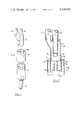
- FIG. 1 of the drawingsis a front perspective exploded view of an improved combination quick disconnect coupling and liquid cutoff valve.
- FIG. 2 of the drawingsis a vertical section of one portion of the improved combination quick disconnect coupling and liquid cutoff valve of FIG. 1.
- FIG. 3 of the drawingsis a vertical section of the improved combined quick disconnect coupling and liquid cutoff valve of FIG. 1 showing a first tubular member adapted for telescopic insertion into and joining with the second tubular member of FIG. 2.
- FIG. 3A of the drawingsis a vertical section of a portion of the second tubular member of FIG. 2 showing in particular a disc valve and resealable channel into the second tubular member.
- FIG. 4 of the drawingsis a vertical section of the improved quick disconnect coupling of FIG. 1 showing in particular a movable sleeve contained within the first tubular member.
- FIG. 5 of the drawingsis a vertical section of the improved quick disconnect coupling of FIG. 1 showing in particular rotation of the movable sleeve of FIG. 4 in an open position so as to allow passage of liquid throught the device.
- FIG. 6 of the drawingsis a vertical section of the quick disconnect coupling of FIG. 1 showing in particular a piercing pin inserted through a penetrate diaphragm resiliently sealing a third tubular member contained within the second tubular member.
- FIG. 7 of the drawingsis a protective overcap used to hermetically seal the first tubular member of FIG. 1 when not connected to the second tubular member of FIG. 1.
- FIG. 8 of the drawingsis a vertical section of the first tubular member of FIG. 1 with the protective overcap of FIG. 7 attached thereto.
- FIG. 9 of the drawingsis a vertical section of an alternative embodiment of the first tubular member of FIG. 1.
- FIG. 10 of the drawingsis a vertical section of an additional alternative embodiment of the first tubular member of FIG. 1.
- FIG. 11 of the drawingsis a front view of a continuous ambulatory peritoneal dialysis system utilizing the improved connector device of the present invention.
- continuous ambulatory peritoneal dialysis system 10comprises a catheter 12 inserted into the peritoneum 14 of the patient 14 and having a length of flexible tubing 16 extending therefrom.
- flexible tubing 16At the end of flexible tubing 16 is quick disconnect coupling and fluid cutoff valve 18. Extending from coupling 18 are lengths of flexible tubing 20 and 22.
- dialysis bag 24At the end of flexible tubing 20 is empty dialysis bag 24.
- dialysis bag 26containing dialysate solution 28.
- dialysate solutionis initially introduced through quick disconnect coupling 18, flexible tubing 16 and catheter 12 into the peritoneum of patient 14.
- dialysate solutionAfter a suitable period, usually about four hours, the dialysate solution has absorbed waste products from patient 14 by osmosis through the peritoneum area. At that time, dialysis bags 24 and 26 are connected to quick disconnect coupling 18. Spent dialysate solution 30 is then drained from the patient into empty dialysis bag 24. Thereafter, fresh dialysate solution 28 is administered to the patient through the same quick disconnect coupling fluid cutoff valve 18 and hence through flexible tubing 16 and catheter 12.
- combination quick disconnect coupling and fluid cutoff valve 18comprises a first tubular member 32 connected to a length of flexible tubing 16 and being constructed so as to allow the passage of fluid therethrough.
- Second tubular member 34is connected to flexible tubing 20 and 22.
- cylindrical sheath 36telescopically circumscribes portion 38 of second tubular member 34 and extends therefrom.
- Cylindrical sheath 36is a tube of a slightly smaller outside diameter than the interior of first tubular member 32 so as to be telescopically insertable therein.
- cylindrical sheath 36is slidably positioned on second tubular member 34, for the following reason.
- third tubular member 40Concentrically positioned within second tubular member 34 is third tubular member 40 which is connected at first end 42 to flexible tubing 22 and is sealed by penetrable, resilient diaphragm member 44 at second end 46.
- Hollow tubular piercing pin 48is disposed rearwardly within and is attached to cylindrical sheath 36. In the embodiment illustrated, piercing pin 48 is affixed to sheath 36 by circular collar 50.
- spent dialysate solution 30may pass through first tubular member 32, piercing pin 48, second tubular member 34, flexible tubing 20 and into empty dialysate bag 24 when cylindrical sheath 36 is disposed as shown.
- cylindrical sheath 36may be moved rearwardly on second tubular member 34, so as to cause piercing pin 48 to penetrate resilient diaphragm member 44 (best seen in FIG. 6).
- piercing pin 48to penetrate resilient diaphragm member 44 (best seen in FIG. 6).
- the fluid connection to flexible tubing 20is sealed, and conversely, the passage of fresh dialysis solution 28 from flexible container 26 through flexible tubing 22, third tubular member 40 and piercing pin 48 may begin.
- the selective flow of spent dialysate solution 30 or fresh dialysate solution 28may be effected simply by operating liquid cutoff valve 18.
- first tubular member 32includes movable sleeve means 52 disposed within first tubular member 32.
- Movable sleeve means 52is partially closed at first end 54 and has aperture 56 extending therethrough.
- lug member 58shown in FIG. 4, extends between movable sleeve 52 and cylindrical sheath 36.
- Lug member 58is constructed and arranged for engagement with corresponding slots 60 integrally formed in movable sleeve means 52 so that as second tubular member 34 is rotated, a corresponding rotation of movable sleeve 52 occurs, thereby opening aperture 56 to the flow of liquid therethrough.
- first tubular member 32 and second tubular member 34may include a resealable channel 62 extending through first tubular member 32, second tubular member 34 and cylindrical sheath 36.
- sealable channel 62includes a disc valve 64 which allows selective passage of liquid therein.
- Channel 62includes a series of capillaries extending throughout the device and allowing the passage of an antimicrobial agent such a betadine into the connection so as to substantially sterilize the area therein.
- second tubular member 34includes cowling member 66 concentrically disposed about and attached to movable cylindrical sheath 36.
- Cowling 66is of an inside diameter slightly larger than the outside diameter of first tubular member 32 so as to telescopically receive first tubular member 32 therein and be attached thereto.
- Cowling 66is designed to prevent the digital contamination of cylindrical sheath 36 or piercing pin 48 during connection of the device.
- first tubular member 32contains an elastomeric seal 68 within first tubular member 32 at first end 70 of cylindrical recess 72. Elastomeric seal 68 abuts against movable sleeve 52. After cylindrical sheath 36 is inserted into movable sleeve 52 and second tubular member 34 is rotated, aperture 56 is moved into an open position for the passage of liquid through circular aperture 74. Thereafter, rotation of first tubular member 32 causes movable sleeve 51 to rotate until aperture 56 is no longer aligned with aperture 74 so as to prevent the further passage of liquid therethrough. As a result, the flow of liquid between first tubular member 32 and second tubular member 34 may be selectively controlled. In addition, the area exposed to contamination prior to connection is substantially reduced to circular aperture 74, rather than having a flow through a previously contaminated chamber.
- first tubular member 32may alternately include a resilient sealing mechanism 90 in the form of a foam pad, rather than an elastomeric seal disposed between movable sleeve 52 and first tubular member 32 so as to hermetically seal same.
- resilient sealing member 90includes aperture 91 which allows the passage of liquid when aperture 56 and movable sleeve 52 is aligned therewith.
- Resilient sealing member 90preferably comprises a foam pad impregnated with an antimicrobial agent such as betadine.
- an antimicrobial agentsuch as betadine.
- coupling device 18is both sterilizable and sterility maintaining when first tubular member 32 and second tubular member 34 are joined in a sterile condition.
- the material of which connecting mechanism 18 is constructedmust be sterilizable, such as polypropylene, polycarbonate or other rigid or semi-rigid plastic materials.
- first tubular member 32may simply contain piercing pin 48 extending inwardly therefrom and adapted for penetration of pentrable sealing member 44 upon full insertion of second tubular member 34 into first tubular member 32.
- piercing pin 48allows the passage of spent dialysate solution 30 until third tubular member 40 is sufficiently advanced so as to cause diaphragm 44 to be pierced by piercing pin 48.
- fresh dialysate solution 28flows through piercing pin 48.
- piercing pin 48may be attached directly to movable sleeve 52 in alignment with aperture 56. Again, the operation of the device is substantially the same.
- cylindrical sheath 36is eliminated so that the second tubular member 34 is simply advanced progressively into first tubular member 32, in order to drain spent dialysate solution 30 and then re-infuse fresh dialysate solution 28.
- movable sleeve member 52may comprise a slidable sleeve member 76 rather than being rotatable as in the previous embodiments.
- aperture 56is aligned with corresponding aperture 78 in first tubular member 32 when flow of liquid is required.
- the inventionfurther contemplates the use of a coupling mechanism 80 between first tubular member 32 and second tubular member 34 (shown in FIG. 2).
- coupling mechanism 80comprises a bayonet locking mechanism consisting of slots 82 and 84 extending inwardly on first tubular member 32 and adapted for locking engagement with corresponding lugs 58 and 59 (best seen in FIG. 2), disposed within second tubular member 34 so as to fixedly position first tubular member 32 and second tubular member 34 together.
- lugs 86 and 87may extend outwardly on first tubular member 32, adapted for engagement with corresponding slots, (not shown), in second tubular member 34.
- FIG. 10further shows that sleeve 76 may be both rotatable and slidable if so desired.
- lug 88is slidably positioned within slot 89 to prevent undesired rotation.
- protective cap member 92is provided for hermetic engagement with and hermetic sealing of first tubular member 32.
- Protective cap 92comprises a tubular member closed at first end 94 and having an inside diameter slightly larger than the outside diameter of first tubular member 32.
- protective cap 94may be affixed about and hermetically seal first tubular member 32.
- protective cap member 92includes a resilient antiseptic plug 96 coaxially disposed therein and adapted for telescopic reception by and sealing of second end 98 of first tubular member 32.
Landscapes
- Health & Medical Sciences (AREA)
- Heart & Thoracic Surgery (AREA)
- Pulmonology (AREA)
- Engineering & Computer Science (AREA)
- Anesthesiology (AREA)
- Biomedical Technology (AREA)
- Hematology (AREA)
- Life Sciences & Earth Sciences (AREA)
- Animal Behavior & Ethology (AREA)
- General Health & Medical Sciences (AREA)
- Public Health (AREA)
- Veterinary Medicine (AREA)
- External Artificial Organs (AREA)
Abstract
Description
Claims (23)
Priority Applications (1)
| Application Number | Priority Date | Filing Date | Title |
|---|---|---|---|
| US06/219,017US4338933A (en) | 1980-12-22 | 1980-12-22 | Combination quick disconnect coupling and liquid cutoff valve |
Applications Claiming Priority (1)
| Application Number | Priority Date | Filing Date | Title |
|---|---|---|---|
| US06/219,017US4338933A (en) | 1980-12-22 | 1980-12-22 | Combination quick disconnect coupling and liquid cutoff valve |
Publications (1)
| Publication Number | Publication Date |
|---|---|
| US4338933Atrue US4338933A (en) | 1982-07-13 |
Family
ID=22817464
Family Applications (1)
| Application Number | Title | Priority Date | Filing Date |
|---|---|---|---|
| US06/219,017Expired - Fee RelatedUS4338933A (en) | 1980-12-22 | 1980-12-22 | Combination quick disconnect coupling and liquid cutoff valve |
Country Status (1)
| Country | Link |
|---|---|
| US (1) | US4338933A (en) |
Cited By (83)
| Publication number | Priority date | Publication date | Assignee | Title |
|---|---|---|---|---|
| US4433971A (en) | 1981-06-30 | 1984-02-28 | Minnesota Mining And Manufacturing Company | Integrated cardioplegia delivery system |
| US4436125A (en) | 1982-03-17 | 1984-03-13 | Colder Products Company | Quick connect coupling |
| EP0114677A3 (en)* | 1983-01-24 | 1984-08-22 | George A. Lopez | Medical connector system |
| US4507113A (en)* | 1982-11-22 | 1985-03-26 | Derata Corporation | Hypodermic jet injector |
| US4541457A (en)* | 1982-03-17 | 1985-09-17 | Colder Products Company | Two-way uncoupling valve assembly |
| US4568330A (en)* | 1983-06-02 | 1986-02-04 | Minnesota Mining And Manufacturing Company | Cardioplegia delivery system with improved bubble trap |
| EP0118474A4 (en)* | 1982-09-10 | 1986-04-15 | Baxter Travenol Lab | Automatic connection and disconnection. |
| US4617012A (en)* | 1985-10-29 | 1986-10-14 | Manresa, Inc. | Sterile connector with movable connection member |
| US4655741A (en)* | 1985-08-27 | 1987-04-07 | Takeo Jyuji | Blood component restoration apparatus |
| US4735608A (en)* | 1986-05-14 | 1988-04-05 | Del F. Kahan | Apparatus for storing and reconstituting antibiotics with intravenous fluids |
| US4745950A (en)* | 1985-04-12 | 1988-05-24 | Fresenius Ag | Connector for peritoneal dialysis |
| US4752292A (en)* | 1983-01-24 | 1988-06-21 | Icu Medical, Inc. | Medical connector |
| US4878516A (en)* | 1985-04-12 | 1989-11-07 | Fresenius Ag | Arrangement for peritoneal dialysis and connector therefore |
| USD318795S (en) | 1989-02-16 | 1991-08-06 | Triparte, Ltd. | Pouch |
| US5088984A (en)* | 1990-10-03 | 1992-02-18 | Tri-State Hospital Supply Corporation | Medical connector |
| US5156603A (en)* | 1989-03-14 | 1992-10-20 | Svend Andersen Plastic Industri A/S | Slide valve |
| US5199947A (en)* | 1983-01-24 | 1993-04-06 | Icu Medical, Inc. | Method of locking an influent line to a piggyback connector |
| US5281206A (en)* | 1983-01-24 | 1994-01-25 | Icu Medical, Inc. | Needle connector with rotatable collar |
| US5292308A (en)* | 1993-05-04 | 1994-03-08 | Ryan Dana W | Three piece intravenous line connector |
| US5344414A (en)* | 1983-01-24 | 1994-09-06 | Icu Medical Inc. | Medical connector |
| US5391163A (en)* | 1992-01-31 | 1995-02-21 | Inpaco Corporation | Pouch for administering medical fluids |
| US5423775A (en)* | 1994-01-21 | 1995-06-13 | Winfield Industries | Locking connector assembly |
| US5533996A (en)* | 1994-08-24 | 1996-07-09 | Baxter International, Inc. | Transfer set connector with permanent, integral cam opening closure and a method of using the same |
| US5645539A (en)* | 1994-11-14 | 1997-07-08 | Innocare One, Ltd. | Elongated medical channel assembly and method of preventing dislodgement |
| US5657963A (en)* | 1993-06-16 | 1997-08-19 | United States Surgical Corporation | Seal assembly for accommodating introduction of surgical instruments |
| US5685866A (en)* | 1991-12-18 | 1997-11-11 | Icu Medical, Inc. | Medical valve and method of use |
| US5688254A (en)* | 1983-01-24 | 1997-11-18 | Icu Medical, Inc. | Medical connector |
| US5715863A (en)* | 1996-05-13 | 1998-02-10 | Paczonay; Joseph R. | Tube quick disconnector |
| USD393722S (en) | 1996-04-04 | 1998-04-21 | Icu Medical, Inc. | Locking blunt cannula |
| US5800383A (en)* | 1996-07-17 | 1998-09-01 | Aquarius Medical Corporation | Fluid management system for arthroscopic surgery |
| US5810792A (en)* | 1996-04-03 | 1998-09-22 | Icu Medical, Inc. | Locking blunt cannula |
| US5830180A (en)* | 1996-07-17 | 1998-11-03 | Aquarius Medical Corporation | Fluid management system for arthroscopic surgery |
| US5957898A (en)* | 1997-05-20 | 1999-09-28 | Baxter International Inc. | Needleless connector |
| US6024720A (en)* | 1995-07-18 | 2000-02-15 | Aquarius Medical Corporation | Fluid management system for arthroscopic surgery |
| US6096011A (en)* | 1998-01-29 | 2000-08-01 | Medrad, Inc. | Aseptic connector and fluid delivery system using such an aseptic connector |
| US6261282B1 (en) | 1997-05-20 | 2001-07-17 | Baxter International Inc. | Needleless connector |
| EP1009360A4 (en)* | 1996-09-30 | 2002-03-20 | Duxbury Scient Inc | Blood collection system and coupling |
| US20020040207A1 (en)* | 1995-12-15 | 2002-04-04 | Lopez George A. | Medical valve with fluid escape space |
| EP1279409A2 (en) | 2001-07-25 | 2003-01-29 | Fresenius Medical Care Deutschland GmbH | Method and device, as well as connector and container for concentrate, for the preparation of solutions |
| US20030028182A1 (en)* | 1999-04-21 | 2003-02-06 | Cryocath Technologies Inc. | Cryoablation catheter handle |
| US6599273B1 (en) | 1991-12-18 | 2003-07-29 | Icu Medical, Inc. | Fluid transfer device and method of use |
| US20040030321A1 (en)* | 2000-07-11 | 2004-02-12 | Fangrow Thomas F. | Medical valve with positive flow characteristics |
| US20040068239A1 (en)* | 2002-10-04 | 2004-04-08 | Utterberg David S. | Injection site for male luer or other tubular connector |
| US20040068238A1 (en)* | 2002-10-04 | 2004-04-08 | Utterberg David S. | Injection site for male luer or other tubular connector |
| US20050197646A1 (en)* | 2002-02-11 | 2005-09-08 | Brian Connell | Dialysis connector with retention and feedback features |
| US20060173420A1 (en)* | 2005-02-01 | 2006-08-03 | Fangrow Thomas F Jr | Check valve for medical Y-site |
| US20060211998A1 (en)* | 2004-11-05 | 2006-09-21 | Fangrow Thomas F | Soft-grip medical connector |
| US20070129705A1 (en)* | 2005-12-01 | 2007-06-07 | Medrad, Inc. | Fluid delivery system, fluid path, and medical connector for use with the fluid delivery system and fluid path |
| US20080086087A1 (en)* | 2004-04-16 | 2008-04-10 | Spohn Michael A | Fluid delivery system including a fluid path set with sterile check valve connector |
| US20080217915A1 (en)* | 2005-03-04 | 2008-09-11 | Nils Arthun | Method and Device for Interconnecting, Sealed Against Contamination, the Ends of Elongate Elements Such as Tubes or Pipes |
| US20090012458A1 (en)* | 2007-07-05 | 2009-01-08 | Baxter International Inc. | Dialysis system having dual patient line connection and prime |
| US20090012459A1 (en)* | 2007-07-05 | 2009-01-08 | Baxter International Inc. | Peritoneal dialysis patient connection system using ultraviolet light emitting diodes |
| US20090012455A1 (en)* | 2007-07-05 | 2009-01-08 | Baxter International Inc. | Dialysis system having supply container autoconnection |
| US20090012451A1 (en)* | 2007-07-05 | 2009-01-08 | Baxter International Inc. | Peritoneal dialysis patient connection system |
| US20090148934A1 (en)* | 2006-06-20 | 2009-06-11 | General Biotechnology, Llc | Systems and Methods for Cryopreservation of Cells |
| US7611503B2 (en) | 2004-04-16 | 2009-11-03 | Medrad, Inc. | Fluid delivery system, fluid path set, sterile connector and improved drip chamber and pressure isolation mechanism |
| US7635357B2 (en) | 1994-06-20 | 2009-12-22 | Mayer Bruno Franz P | Needleless injection site |
| US7713250B2 (en) | 2001-12-07 | 2010-05-11 | Becton, Dickinson And Company | Needleless luer access connector |
| US20100130919A1 (en)* | 2008-11-21 | 2010-05-27 | Baxter International Inc. | Systems and methods for removing air from the patient's peritoneal cavity |
| US20100130918A1 (en)* | 2008-11-21 | 2010-05-27 | Baxter International Inc. | Systems and methods for removing air from supply containers and associated fill tubing |
| US20100130920A1 (en)* | 2008-11-21 | 2010-05-27 | Baxter International Inc. | Dialysis machine having auto-connection system with roller occluder |
| US20100196873A1 (en)* | 2006-06-20 | 2010-08-05 | Vialco, Llc | Systems and Methods for Cryopreservation of Cells |
| US20100241088A1 (en)* | 2009-03-17 | 2010-09-23 | Baxa Corporation | Hazardous drug handling system, apparatus and method |
| US7887104B1 (en) | 2004-08-16 | 2011-02-15 | Hollis Wilson | Quick connect and disconnect coupler |
| US20110092828A1 (en)* | 2004-04-16 | 2011-04-21 | Spohn Michael A | Fluid Delivery System, Fluid Path Set, and Pressure Isolation Mechanism with Hemodynamic Pressure Dampening Correction |
| USD644731S1 (en) | 2010-03-23 | 2011-09-06 | Icu Medical, Inc. | Medical connector |
| US8105314B2 (en) | 2006-10-25 | 2012-01-31 | Icu Medical, Inc. | Medical connector |
| WO2012177820A1 (en)* | 2011-06-22 | 2012-12-27 | Rich Products Corporation | System, method, and device for preserving blood or its components in gas medium under pressure |
| US8454579B2 (en) | 2009-03-25 | 2013-06-04 | Icu Medical, Inc. | Medical connector with automatic valves and volume regulator |
| US8758306B2 (en) | 2010-05-17 | 2014-06-24 | Icu Medical, Inc. | Medical connectors and methods of use |
| US20150217104A1 (en)* | 2012-08-28 | 2015-08-06 | Fresenius Kabi Deutschland Gmbh | Connector for producing a fluid connection to a second connector, connector system, and method for producing a fluid connection |
| US20150276114A1 (en)* | 2014-03-31 | 2015-10-01 | Hamilton Sunstrand Corporation | Fluid transfer coupling |
| CN106264707A (en)* | 2016-09-28 | 2017-01-04 | 康沣生物科技(上海)有限公司 | Cryoablation snap joint |
| US9586003B2 (en) | 2007-07-05 | 2017-03-07 | Baxter International Inc. | Medical fluid machine with supply autoconnection |
| USD786427S1 (en) | 2014-12-03 | 2017-05-09 | Icu Medical, Inc. | Fluid manifold |
| USD793551S1 (en) | 2014-12-03 | 2017-08-01 | Icu Medical, Inc. | Fluid manifold |
| US10293091B2 (en) | 2007-07-05 | 2019-05-21 | Baxter International Inc. | Dialysis system having an autoconnection mechanism |
| US10369349B2 (en) | 2013-12-11 | 2019-08-06 | Icu Medical, Inc. | Medical fluid manifold |
| US11219752B2 (en)* | 2016-07-29 | 2022-01-11 | Avent, Inc. | Tamper proof connector for enteral feeding devices |
| US11497207B2 (en) | 2017-03-03 | 2022-11-15 | Rich Technologies Holding Company, Llc | Device for preserving blood products and cellular cultures in a gas medium under pressure |
| US20230081788A1 (en)* | 2021-09-13 | 2023-03-16 | Robert Laws | Coupling device and self-sealing valve assemblies for connecting and disconnecting a hose to a fire hydrant |
| US20240368861A1 (en)* | 2023-05-03 | 2024-11-07 | Merrill Manufacturing Company | Wall faucet assembly |
| US12440661B2 (en) | 2022-05-18 | 2025-10-14 | Icu Medical, Inc. | Medical fluid transfer device |
Citations (24)
| Publication number | Priority date | Publication date | Assignee | Title |
|---|---|---|---|---|
| US745815A (en)* | 1903-04-21 | 1903-12-01 | William W Gibson | Hose-coupling. |
| US808446A (en)* | 1904-10-18 | 1905-12-26 | Lemuel D Gill | Coupling. |
| US968711A (en)* | 1909-06-01 | 1910-08-30 | Perley A Griswold | Hydrant. |
| US1580312A (en)* | 1925-04-06 | 1926-04-13 | James F Long | Combined plug valve and hose connection |
| US2275477A (en)* | 1939-11-09 | 1942-03-10 | Edwin P Sundholm | Flow control device |
| US2502206A (en)* | 1946-10-04 | 1950-03-28 | John O Creek | Pressure fluid coupling |
| US3588149A (en)* | 1969-08-13 | 1971-06-28 | Amp Inc | Vacuum or pressure coupling devices |
| US3626980A (en)* | 1968-12-13 | 1971-12-14 | Jan Axel Svensson | Bacteria barrier device |
| US3707972A (en)* | 1971-07-28 | 1973-01-02 | Kendall & Co | Irrigation connector with shut-off valve |
| US3876234A (en)* | 1973-01-11 | 1975-04-08 | Extracorporeal Med Spec | Twist-lock connector |
| US3986508A (en)* | 1973-08-22 | 1976-10-19 | Abcor, Inc. | Sterilizable, medical connector for blood processing |
| US4019512A (en)* | 1975-12-04 | 1977-04-26 | Tenczar Francis J | Adhesively activated sterile connector |
| US4022205A (en)* | 1973-11-05 | 1977-05-10 | Tenczar Francis J | Fluid connectors |
| US4030494A (en)* | 1973-11-05 | 1977-06-21 | Francis Tenczar | Fluid connectors |
| US4046145A (en)* | 1976-06-29 | 1977-09-06 | American Hospital Supply Corporation | Syringe connector |
| US4055179A (en)* | 1975-03-31 | 1977-10-25 | Plastronics, Inc. | Valve for urinary drainage container or similar article |
| US4056116A (en)* | 1976-09-08 | 1977-11-01 | Baxter Travenol Laboratories, Inc. | Valve for interconnecting sterile containers and the like |
| US4076285A (en)* | 1975-08-01 | 1978-02-28 | Erika, Inc. | Laminar flow connector for conduits |
| US4080965A (en)* | 1976-09-30 | 1978-03-28 | Baxter Travenol Laboratories, Inc. | In-line cannula valve assembly |
| DE2809303A1 (en) | 1977-03-03 | 1978-10-05 | Robert P Popovich | METHOD AND DEVICE FOR CONTINUOUS AMBULANCE PERITONEAL DIALYSIS (ABDOMINAL FLUSHING) |
| US4133312A (en)* | 1976-10-13 | 1979-01-09 | Cordis Dow Corp. | Connector for attachment of blood tubing to external arteriovenous shunts and fistulas |
| US4161949A (en)* | 1977-10-27 | 1979-07-24 | Pennwalt Corporation | Aseptic connector |
| US4186752A (en)* | 1978-08-30 | 1980-02-05 | Guerra Luis A | Device for taking blood and for injecting medication |
| US4201406A (en)* | 1978-11-13 | 1980-05-06 | Baxter Travenol Laboratories, Inc. | Spike connector for solution bag |
- 1980
- 1980-12-22USUS06/219,017patent/US4338933A/ennot_activeExpired - Fee Related
Patent Citations (24)
| Publication number | Priority date | Publication date | Assignee | Title |
|---|---|---|---|---|
| US745815A (en)* | 1903-04-21 | 1903-12-01 | William W Gibson | Hose-coupling. |
| US808446A (en)* | 1904-10-18 | 1905-12-26 | Lemuel D Gill | Coupling. |
| US968711A (en)* | 1909-06-01 | 1910-08-30 | Perley A Griswold | Hydrant. |
| US1580312A (en)* | 1925-04-06 | 1926-04-13 | James F Long | Combined plug valve and hose connection |
| US2275477A (en)* | 1939-11-09 | 1942-03-10 | Edwin P Sundholm | Flow control device |
| US2502206A (en)* | 1946-10-04 | 1950-03-28 | John O Creek | Pressure fluid coupling |
| US3626980A (en)* | 1968-12-13 | 1971-12-14 | Jan Axel Svensson | Bacteria barrier device |
| US3588149A (en)* | 1969-08-13 | 1971-06-28 | Amp Inc | Vacuum or pressure coupling devices |
| US3707972A (en)* | 1971-07-28 | 1973-01-02 | Kendall & Co | Irrigation connector with shut-off valve |
| US3876234A (en)* | 1973-01-11 | 1975-04-08 | Extracorporeal Med Spec | Twist-lock connector |
| US3986508A (en)* | 1973-08-22 | 1976-10-19 | Abcor, Inc. | Sterilizable, medical connector for blood processing |
| US4022205A (en)* | 1973-11-05 | 1977-05-10 | Tenczar Francis J | Fluid connectors |
| US4030494A (en)* | 1973-11-05 | 1977-06-21 | Francis Tenczar | Fluid connectors |
| US4055179A (en)* | 1975-03-31 | 1977-10-25 | Plastronics, Inc. | Valve for urinary drainage container or similar article |
| US4076285A (en)* | 1975-08-01 | 1978-02-28 | Erika, Inc. | Laminar flow connector for conduits |
| US4019512A (en)* | 1975-12-04 | 1977-04-26 | Tenczar Francis J | Adhesively activated sterile connector |
| US4046145A (en)* | 1976-06-29 | 1977-09-06 | American Hospital Supply Corporation | Syringe connector |
| US4056116A (en)* | 1976-09-08 | 1977-11-01 | Baxter Travenol Laboratories, Inc. | Valve for interconnecting sterile containers and the like |
| US4080965A (en)* | 1976-09-30 | 1978-03-28 | Baxter Travenol Laboratories, Inc. | In-line cannula valve assembly |
| US4133312A (en)* | 1976-10-13 | 1979-01-09 | Cordis Dow Corp. | Connector for attachment of blood tubing to external arteriovenous shunts and fistulas |
| DE2809303A1 (en) | 1977-03-03 | 1978-10-05 | Robert P Popovich | METHOD AND DEVICE FOR CONTINUOUS AMBULANCE PERITONEAL DIALYSIS (ABDOMINAL FLUSHING) |
| US4161949A (en)* | 1977-10-27 | 1979-07-24 | Pennwalt Corporation | Aseptic connector |
| US4186752A (en)* | 1978-08-30 | 1980-02-05 | Guerra Luis A | Device for taking blood and for injecting medication |
| US4201406A (en)* | 1978-11-13 | 1980-05-06 | Baxter Travenol Laboratories, Inc. | Spike connector for solution bag |
Cited By (209)
| Publication number | Priority date | Publication date | Assignee | Title |
|---|---|---|---|---|
| US4433971A (en) | 1981-06-30 | 1984-02-28 | Minnesota Mining And Manufacturing Company | Integrated cardioplegia delivery system |
| US4541457A (en)* | 1982-03-17 | 1985-09-17 | Colder Products Company | Two-way uncoupling valve assembly |
| US4436125A (en) | 1982-03-17 | 1984-03-13 | Colder Products Company | Quick connect coupling |
| EP0118474A4 (en)* | 1982-09-10 | 1986-04-15 | Baxter Travenol Lab | Automatic connection and disconnection. |
| US4507113A (en)* | 1982-11-22 | 1985-03-26 | Derata Corporation | Hypodermic jet injector |
| US5199947A (en)* | 1983-01-24 | 1993-04-06 | Icu Medical, Inc. | Method of locking an influent line to a piggyback connector |
| US5776116A (en)* | 1983-01-24 | 1998-07-07 | Icu Medical, Inc. | Medical connector |
| US5954708A (en)* | 1983-01-24 | 1999-09-21 | Icu Medical, Inc. | Medical connector |
| US5344414A (en)* | 1983-01-24 | 1994-09-06 | Icu Medical Inc. | Medical connector |
| US5688254A (en)* | 1983-01-24 | 1997-11-18 | Icu Medical, Inc. | Medical connector |
| US4752292A (en)* | 1983-01-24 | 1988-06-21 | Icu Medical, Inc. | Medical connector |
| EP0114677A3 (en)* | 1983-01-24 | 1984-08-22 | George A. Lopez | Medical connector system |
| US5281206A (en)* | 1983-01-24 | 1994-01-25 | Icu Medical, Inc. | Needle connector with rotatable collar |
| US4568330A (en)* | 1983-06-02 | 1986-02-04 | Minnesota Mining And Manufacturing Company | Cardioplegia delivery system with improved bubble trap |
| US4745950A (en)* | 1985-04-12 | 1988-05-24 | Fresenius Ag | Connector for peritoneal dialysis |
| US4878516A (en)* | 1985-04-12 | 1989-11-07 | Fresenius Ag | Arrangement for peritoneal dialysis and connector therefore |
| US4655741A (en)* | 1985-08-27 | 1987-04-07 | Takeo Jyuji | Blood component restoration apparatus |
| US4617012A (en)* | 1985-10-29 | 1986-10-14 | Manresa, Inc. | Sterile connector with movable connection member |
| US4735608A (en)* | 1986-05-14 | 1988-04-05 | Del F. Kahan | Apparatus for storing and reconstituting antibiotics with intravenous fluids |
| USD318795S (en) | 1989-02-16 | 1991-08-06 | Triparte, Ltd. | Pouch |
| US5156603A (en)* | 1989-03-14 | 1992-10-20 | Svend Andersen Plastic Industri A/S | Slide valve |
| US5088984A (en)* | 1990-10-03 | 1992-02-18 | Tri-State Hospital Supply Corporation | Medical connector |
| US6669673B2 (en) | 1991-12-18 | 2003-12-30 | Icu Medical, Inc. | Medical valve |
| US7717883B2 (en) | 1991-12-18 | 2010-05-18 | Icu Medical, Inc. | Medical valve and method of use |
| US7722576B2 (en) | 1991-12-18 | 2010-05-25 | Icu Medical, Inc. | Medical valve and method of use |
| US5685866A (en)* | 1991-12-18 | 1997-11-11 | Icu Medical, Inc. | Medical valve and method of use |
| US7722575B2 (en) | 1991-12-18 | 2010-05-25 | Icu Medical, Inc. | Medical valve and method of use |
| US7713249B2 (en) | 1991-12-18 | 2010-05-11 | Icu Medical, Inc. | Medical valve and method of use |
| US6758833B2 (en) | 1991-12-18 | 2004-07-06 | Icu Medical, Inc. | Medical value |
| US7713248B2 (en) | 1991-12-18 | 2010-05-11 | Icu Medical, Inc. | Medical valve and method of use |
| US7713247B2 (en) | 1991-12-18 | 2010-05-11 | Icu Medical, Inc. | Medical valve and method of use |
| US7717887B2 (en) | 1991-12-18 | 2010-05-18 | Icu Medical, Inc. | Medical valve and method of use |
| US7717886B2 (en) | 1991-12-18 | 2010-05-18 | Icu Medical, Inc. | Medical valve and method of use |
| US5873862A (en)* | 1991-12-18 | 1999-02-23 | Icu Medical, Inc. | Medical valve and method of use |
| US5928204A (en)* | 1991-12-18 | 1999-07-27 | Icu Medical, Inc. | Medical valve and method of use |
| US6682509B2 (en) | 1991-12-18 | 2004-01-27 | Icu Medical, Inc. | Medical valve and method of use |
| US20040002684A1 (en)* | 1991-12-18 | 2004-01-01 | Lopez George A. | Fluid transfer device and method of use |
| US7717884B2 (en) | 1991-12-18 | 2010-05-18 | Icu Medical, Inc. | Medical valve and method of use |
| US6599273B1 (en) | 1991-12-18 | 2003-07-29 | Icu Medical, Inc. | Fluid transfer device and method of use |
| US6132403A (en)* | 1991-12-18 | 2000-10-17 | Icu Medical, Inc. | Medical valve and method of use |
| US7717885B2 (en) | 1991-12-18 | 2010-05-18 | Icu Medical, Inc. | Medical valve and method of use |
| US6572592B1 (en) | 1991-12-18 | 2003-06-03 | Icu Medical, Inc. | Medical valve and method of use |
| US5391163A (en)* | 1992-01-31 | 1995-02-21 | Inpaco Corporation | Pouch for administering medical fluids |
| US5292308A (en)* | 1993-05-04 | 1994-03-08 | Ryan Dana W | Three piece intravenous line connector |
| US5657963A (en)* | 1993-06-16 | 1997-08-19 | United States Surgical Corporation | Seal assembly for accommodating introduction of surgical instruments |
| US5423775A (en)* | 1994-01-21 | 1995-06-13 | Winfield Industries | Locking connector assembly |
| US7635357B2 (en) | 1994-06-20 | 2009-12-22 | Mayer Bruno Franz P | Needleless injection site |
| US5533996A (en)* | 1994-08-24 | 1996-07-09 | Baxter International, Inc. | Transfer set connector with permanent, integral cam opening closure and a method of using the same |
| US5645539A (en)* | 1994-11-14 | 1997-07-08 | Innocare One, Ltd. | Elongated medical channel assembly and method of preventing dislodgement |
| US6024720A (en)* | 1995-07-18 | 2000-02-15 | Aquarius Medical Corporation | Fluid management system for arthroscopic surgery |
| US6635044B2 (en) | 1995-12-15 | 2003-10-21 | Icu Medical, Inc. | Medical valve with fluid escape space |
| US8002765B2 (en) | 1995-12-15 | 2011-08-23 | Icu Medical, Inc. | Medical valve with fluid escape space |
| US20020040207A1 (en)* | 1995-12-15 | 2002-04-04 | Lopez George A. | Medical valve with fluid escape space |
| US5810792A (en)* | 1996-04-03 | 1998-09-22 | Icu Medical, Inc. | Locking blunt cannula |
| USD393722S (en) | 1996-04-04 | 1998-04-21 | Icu Medical, Inc. | Locking blunt cannula |
| US5715863A (en)* | 1996-05-13 | 1998-02-10 | Paczonay; Joseph R. | Tube quick disconnector |
| US5830180A (en)* | 1996-07-17 | 1998-11-03 | Aquarius Medical Corporation | Fluid management system for arthroscopic surgery |
| US5800383A (en)* | 1996-07-17 | 1998-09-01 | Aquarius Medical Corporation | Fluid management system for arthroscopic surgery |
| EP1009360A4 (en)* | 1996-09-30 | 2002-03-20 | Duxbury Scient Inc | Blood collection system and coupling |
| US5957898A (en)* | 1997-05-20 | 1999-09-28 | Baxter International Inc. | Needleless connector |
| US6669681B2 (en) | 1997-05-20 | 2003-12-30 | Baxter International Inc. | Needleless connector |
| US6261282B1 (en) | 1997-05-20 | 2001-07-17 | Baxter International Inc. | Needleless connector |
| US6344033B1 (en) | 1997-05-20 | 2002-02-05 | Baxter International, Inc. | Needleless connector |
| USRE43142E1 (en) | 1997-05-20 | 2012-01-24 | Baxter International, Inc. | Needleless connector |
| US6096011A (en)* | 1998-01-29 | 2000-08-01 | Medrad, Inc. | Aseptic connector and fluid delivery system using such an aseptic connector |
| US6440107B1 (en) | 1998-01-29 | 2002-08-27 | Medrad, Inc. | Fluid delivery system and an aseptic connector for use therewith |
| US20030028182A1 (en)* | 1999-04-21 | 2003-02-06 | Cryocath Technologies Inc. | Cryoablation catheter handle |
| US20060004331A1 (en)* | 2000-07-11 | 2006-01-05 | Fangrow Thomas F Jr | Medical valve with positive flow characteristics |
| US6916309B2 (en) | 2000-07-11 | 2005-07-12 | Icu Medical, Inc. | Medical valve with positive flow characteristics |
| US8870850B2 (en) | 2000-07-11 | 2014-10-28 | Icu Medical, Inc. | Medical connector |
| US20040030321A1 (en)* | 2000-07-11 | 2004-02-12 | Fangrow Thomas F. | Medical valve with positive flow characteristics |
| US6695817B1 (en) | 2000-07-11 | 2004-02-24 | Icu Medical, Inc. | Medical valve with positive flow characteristics |
| US8444628B2 (en) | 2000-07-11 | 2013-05-21 | Icu Medical, Inc. | Needleless medical connector |
| US20060264844A1 (en)* | 2000-07-11 | 2006-11-23 | Fangrow Thomas F Jr | Medical valve with positive flow characteristics |
| US20060224127A1 (en)* | 2000-07-11 | 2006-10-05 | Fangrow Thomas F Jr | Medical valve with positive flow characteristics |
| US8221391B2 (en) | 2000-07-11 | 2012-07-17 | Icu Medical, Inc. | Needleless medical connector |
| US20060276758A1 (en)* | 2000-07-11 | 2006-12-07 | Fangrow Thomas F Jr | Medical valve with positive flow characteristics |
| US7628774B2 (en) | 2000-07-11 | 2009-12-08 | Icu Medical, Inc. | Needleless Medical Connector |
| US9238129B2 (en) | 2000-07-11 | 2016-01-19 | Icu Medical, Inc. | Medical connector |
| US7497849B2 (en) | 2000-07-11 | 2009-03-03 | Icu Medical, Inc. | High flow rate needleless medical connector |
| US7763199B2 (en) | 2000-07-11 | 2010-07-27 | Icu Medical, Inc. | Method of making a seal having slit formed therein |
| EP1279409A2 (en) | 2001-07-25 | 2003-01-29 | Fresenius Medical Care Deutschland GmbH | Method and device, as well as connector and container for concentrate, for the preparation of solutions |
| EP1279409A3 (en)* | 2001-07-25 | 2003-07-23 | Fresenius Medical Care Deutschland GmbH | Method and device, as well as connector and container for concentrate, for the preparation of solutions |
| US7947032B2 (en) | 2001-12-07 | 2011-05-24 | Becton, Dickinson And Company | Needleless luer access connector |
| US20100179489A1 (en)* | 2001-12-07 | 2010-07-15 | Becton, Dickinson And Company | Needleless luer access connector |
| US7713250B2 (en) | 2001-12-07 | 2010-05-11 | Becton, Dickinson And Company | Needleless luer access connector |
| US20050197646A1 (en)* | 2002-02-11 | 2005-09-08 | Brian Connell | Dialysis connector with retention and feedback features |
| US7708714B2 (en) | 2002-02-11 | 2010-05-04 | Baxter International Inc. | Dialysis connector with retention and feedback features |
| US7025744B2 (en) | 2002-10-04 | 2006-04-11 | Dsu Medical Corporation | Injection site for male luer or other tubular connector |
| US8377039B2 (en) | 2002-10-04 | 2013-02-19 | Nxstage Medical, Inc. | Injection site for male luer or other tubular connector |
| US20040068238A1 (en)* | 2002-10-04 | 2004-04-08 | Utterberg David S. | Injection site for male luer or other tubular connector |
| US20040068239A1 (en)* | 2002-10-04 | 2004-04-08 | Utterberg David S. | Injection site for male luer or other tubular connector |
| US8647312B2 (en) | 2002-10-04 | 2014-02-11 | Nxstage Medical, Inc. | Injection site for male luer or other tubular connector |
| US20110092828A1 (en)* | 2004-04-16 | 2011-04-21 | Spohn Michael A | Fluid Delivery System, Fluid Path Set, and Pressure Isolation Mechanism with Hemodynamic Pressure Dampening Correction |
| US8992489B2 (en) | 2004-04-16 | 2015-03-31 | Bayer Medical Care Inc. | Fluid delivery system, fluid path set, and pressure isolation mechanism with hemodynamic pressure dampening correction |
| US7611503B2 (en) | 2004-04-16 | 2009-11-03 | Medrad, Inc. | Fluid delivery system, fluid path set, sterile connector and improved drip chamber and pressure isolation mechanism |
| US9895527B2 (en) | 2004-04-16 | 2018-02-20 | Bayer Healthcare Llc | Fluid delivery system, fluid path set, and pressure isolation mechanism with hemodynamic pressure dampening correction |
| US8540698B2 (en) | 2004-04-16 | 2013-09-24 | Medrad, Inc. | Fluid delivery system including a fluid path set and a check valve connector |
| US20080086087A1 (en)* | 2004-04-16 | 2008-04-10 | Spohn Michael A | Fluid delivery system including a fluid path set with sterile check valve connector |
| US7887104B1 (en) | 2004-08-16 | 2011-02-15 | Hollis Wilson | Quick connect and disconnect coupler |
| US9415200B2 (en) | 2004-11-05 | 2016-08-16 | Icu Medical, Inc. | Medical connector |
| US11883623B2 (en) | 2004-11-05 | 2024-01-30 | Icu Medical, Inc. | Medical connector |
| US20070112313A1 (en)* | 2004-11-05 | 2007-05-17 | Fangrow Thomas F | Soft-grip medical connector |
| US20060264910A1 (en)* | 2004-11-05 | 2006-11-23 | Fangrow Thomas F | Soft-grip medical connector |
| US9186494B2 (en) | 2004-11-05 | 2015-11-17 | Icu Medical, Inc. | Medical connector |
| US9884176B2 (en) | 2004-11-05 | 2018-02-06 | Icu Medical, Inc. | Medical connector |
| US20060270999A1 (en)* | 2004-11-05 | 2006-11-30 | Fangrow Thomas F | Soft-grip medical connector |
| US20060271016A1 (en)* | 2004-11-05 | 2006-11-30 | Fangrow Thomas F | Soft-grip medical connector |
| US10722698B2 (en) | 2004-11-05 | 2020-07-28 | Icu Medical, Inc. | Medical connector |
| US7824393B2 (en) | 2004-11-05 | 2010-11-02 | Icu Medical, Inc. | Medical connector having high flow rate characteristics |
| US20060211998A1 (en)* | 2004-11-05 | 2006-09-21 | Fangrow Thomas F | Soft-grip medical connector |
| US7670322B2 (en) | 2005-02-01 | 2010-03-02 | Icu Medical, Inc. | Check valve for medical Y-site |
| US20060212005A1 (en)* | 2005-02-01 | 2006-09-21 | Fangrow Thomas F Jr | Check valve for medical Y-site |
| US20060200096A1 (en)* | 2005-02-01 | 2006-09-07 | Fangrow Thomas F Jr | Check valve for medical Y-site |
| US20060173420A1 (en)* | 2005-02-01 | 2006-08-03 | Fangrow Thomas F Jr | Check valve for medical Y-site |
| US20060264853A1 (en)* | 2005-02-01 | 2006-11-23 | Fangrow Thomas F Jr | Check valve for medical Y-site |
| US7931627B2 (en) | 2005-02-01 | 2011-04-26 | Icu Medical, Inc. | Check valve for medical Y-site |
| US20060264854A1 (en)* | 2005-02-01 | 2006-11-23 | Fangrow Thomas F Jr | Check valve for medical Y-site |
| US20060264852A1 (en)* | 2005-02-01 | 2006-11-23 | Fangrow Thomas F Jr | Check valve for medical Y-site |
| US20080217915A1 (en)* | 2005-03-04 | 2008-09-11 | Nils Arthun | Method and Device for Interconnecting, Sealed Against Contamination, the Ends of Elongate Elements Such as Tubes or Pipes |
| US7922211B2 (en)* | 2005-03-04 | 2011-04-12 | Millipore Ab | Method and device for interconnecting, sealed against contamination, the ends of elongate elements such as tubes or pipes |
| US8852167B2 (en) | 2005-12-01 | 2014-10-07 | Bayer Medical Care Inc. | Medical connector |
| US20070129705A1 (en)* | 2005-12-01 | 2007-06-07 | Medrad, Inc. | Fluid delivery system, fluid path, and medical connector for use with the fluid delivery system and fluid path |
| US9827410B2 (en) | 2005-12-01 | 2017-11-28 | Bayer Healthcare Llc | Medical connector for use with the fluid delivery system and fluid path |
| US20100196873A1 (en)* | 2006-06-20 | 2010-08-05 | Vialco, Llc | Systems and Methods for Cryopreservation of Cells |
| US8222027B2 (en)* | 2006-06-20 | 2012-07-17 | Cook General Biotechnolgy, LLC | Systems and methods for cryopreservation of cells |
| US10271543B2 (en) | 2006-06-20 | 2019-04-30 | Cook General Biotechnology Llc | Systems and methods for cryopreservation of cells |
| US8936905B2 (en) | 2006-06-20 | 2015-01-20 | Cook General Biotechnology Llc | Systems and methods for cryopreservation of cells |
| US9565854B2 (en) | 2006-06-20 | 2017-02-14 | Cook General Biotechnology Llc | Systems and methods for cryopreservation of cells |
| US8709797B2 (en) | 2006-06-20 | 2014-04-29 | Cook General Biotechnology Llc | Systems and methods for cryopreservation of cells |
| US9877475B2 (en) | 2006-06-20 | 2018-01-30 | Cook General Biotechnology Llc | Systems and methods for cryopreservation of cells |
| US20090148934A1 (en)* | 2006-06-20 | 2009-06-11 | General Biotechnology, Llc | Systems and Methods for Cryopreservation of Cells |
| US8628515B2 (en) | 2006-10-25 | 2014-01-14 | Icu Medical, Inc. | Medical connector |
| US9533137B2 (en) | 2006-10-25 | 2017-01-03 | Icu Medical, Inc. | Medical connector |
| US8398607B2 (en) | 2006-10-25 | 2013-03-19 | Icu Medical, Inc. | Medical connector |
| US8105314B2 (en) | 2006-10-25 | 2012-01-31 | Icu Medical, Inc. | Medical connector |
| US11311657B2 (en) | 2007-07-05 | 2022-04-26 | Baxter International Inc. | Dialysis system for mixing treatment fluid at time of use |
| US10293091B2 (en) | 2007-07-05 | 2019-05-21 | Baxter International Inc. | Dialysis system having an autoconnection mechanism |
| US8469545B2 (en) | 2007-07-05 | 2013-06-25 | Baxter Healthcare Inc. | Peritoneal dialysis connection system and method for using ultraviolet light emitting diodes |
| US11730868B2 (en) | 2007-07-05 | 2023-08-22 | Baxter International Inc. | Dialysis system having an autoconnection mechanism |
| US8257299B2 (en) | 2007-07-05 | 2012-09-04 | Baxter International | Dialysis methods and systems having autoconnection and autoidentification |
| US8764702B2 (en) | 2007-07-05 | 2014-07-01 | Baxter International Inc. | Dialysis system having dual patient line connection and prime |
| US8197087B2 (en) | 2007-07-05 | 2012-06-12 | Baxter International Inc. | Peritoneal dialysis patient connection system using ultraviolet light emitting diodes |
| US9586003B2 (en) | 2007-07-05 | 2017-03-07 | Baxter International Inc. | Medical fluid machine with supply autoconnection |
| US8157761B2 (en) | 2007-07-05 | 2012-04-17 | Baxter International Inc. | Peritoneal dialysis patient connection system |
| US8911109B2 (en) | 2007-07-05 | 2014-12-16 | Baxter Healthcare Inc. | Peritoneal dialysis connection system and method for using ultraviolet light emitting diodes |
| US8083709B2 (en) | 2007-07-05 | 2011-12-27 | Baxter International Inc. | Dialysis method having supply container autoconnection |
| US8986243B2 (en) | 2007-07-05 | 2015-03-24 | Baxter International Inc. | Peritoneal dialysis patient connection system |
| US11931497B2 (en) | 2007-07-05 | 2024-03-19 | Baxter International Inc. | System and method for preparing peritoneal dialysis fluid at the time of use |
| US7736328B2 (en) | 2007-07-05 | 2010-06-15 | Baxter International Inc. | Dialysis system having supply container autoconnection |
| US10335532B2 (en) | 2007-07-05 | 2019-07-02 | Baxter International Inc. | Dialysis system having autoidentification mechanism |
| US8597230B2 (en) | 2007-07-05 | 2013-12-03 | Baxter International Inc. | Dialysis system having supply container autoconnection |
| US20090012458A1 (en)* | 2007-07-05 | 2009-01-08 | Baxter International Inc. | Dialysis system having dual patient line connection and prime |
| US20090012459A1 (en)* | 2007-07-05 | 2009-01-08 | Baxter International Inc. | Peritoneal dialysis patient connection system using ultraviolet light emitting diodes |
| US20090012451A1 (en)* | 2007-07-05 | 2009-01-08 | Baxter International Inc. | Peritoneal dialysis patient connection system |
| US20090012455A1 (en)* | 2007-07-05 | 2009-01-08 | Baxter International Inc. | Dialysis system having supply container autoconnection |
| US20100229366A1 (en)* | 2007-07-05 | 2010-09-16 | Baxter International Inc. | Dialysis method having supply container autoconnection |
| US9931454B2 (en) | 2008-11-21 | 2018-04-03 | Baxter International Inc. | Dialysis machine having auto-connection system with roller occluder |
| US9044544B2 (en) | 2008-11-21 | 2015-06-02 | Baxter International Inc. | Dialysis machine having auto-connection system with roller occluder |
| US20100130920A1 (en)* | 2008-11-21 | 2010-05-27 | Baxter International Inc. | Dialysis machine having auto-connection system with roller occluder |
| US9555180B2 (en) | 2008-11-21 | 2017-01-31 | Baxter International Inc. | Systems and methods for removing air from the patient's peritoneal cavity |
| US20100130918A1 (en)* | 2008-11-21 | 2010-05-27 | Baxter International Inc. | Systems and methods for removing air from supply containers and associated fill tubing |
| US20100130919A1 (en)* | 2008-11-21 | 2010-05-27 | Baxter International Inc. | Systems and methods for removing air from the patient's peritoneal cavity |
| US20100241088A1 (en)* | 2009-03-17 | 2010-09-23 | Baxa Corporation | Hazardous drug handling system, apparatus and method |
| US8864725B2 (en) | 2009-03-17 | 2014-10-21 | Baxter Corporation Englewood | Hazardous drug handling system, apparatus and method |
| US9278206B2 (en) | 2009-03-25 | 2016-03-08 | Icu Medical, Inc. | Medical connectors and methods of use |
| US10799692B2 (en) | 2009-03-25 | 2020-10-13 | Icu Medical, Inc. | Medical connectors and methods of use |
| US12285584B2 (en) | 2009-03-25 | 2025-04-29 | Icu Medical, Inc. | Medical connector with elongated portion within seal collar |
| US12102786B2 (en) | 2009-03-25 | 2024-10-01 | Icu Medical, Inc. | Medical connector with elongated portion within seal collar |
| US12059545B2 (en) | 2009-03-25 | 2024-08-13 | Icu Medical, Inc. | Medical connector with elongated portion within seal collar |
| US11986618B1 (en) | 2009-03-25 | 2024-05-21 | Icu Medical, Inc. | Medical connector having elongated portion within seal collar |
| US9440060B2 (en) | 2009-03-25 | 2016-09-13 | Icu Medical, Inc. | Medical connectors and methods of use |
| US11931539B2 (en) | 2009-03-25 | 2024-03-19 | Icu Medical, Inc. | Medical connectors and methods of use |
| US11896795B2 (en) | 2009-03-25 | 2024-02-13 | Icu Medical, Inc | Medical connector having elongated portion within closely conforming seal collar |
| US8454579B2 (en) | 2009-03-25 | 2013-06-04 | Icu Medical, Inc. | Medical connector with automatic valves and volume regulator |
| US11376411B2 (en) | 2009-03-25 | 2022-07-05 | Icu Medical, Inc. | Medical connectors and methods of use |
| US10086188B2 (en) | 2009-03-25 | 2018-10-02 | Icu Medical, Inc. | Medical connectors and methods of use |
| US10391293B2 (en) | 2009-03-25 | 2019-08-27 | Icu Medical, Inc. | Medical connectors and methods of use |
| USD1003434S1 (en) | 2010-03-23 | 2023-10-31 | Icu Medical, Inc. | Medical connector seal |
| USD1029246S1 (en) | 2010-03-23 | 2024-05-28 | Icu Medical, Inc. | Medical connector seal |
| USD644731S1 (en) | 2010-03-23 | 2011-09-06 | Icu Medical, Inc. | Medical connector |
| US9205243B2 (en) | 2010-05-17 | 2015-12-08 | Icu Medical, Inc. | Medical connectors and methods of use |
| US9750926B2 (en) | 2010-05-17 | 2017-09-05 | Icu Medical, Inc. | Medical connectors and methods of use |
| US10195413B2 (en) | 2010-05-17 | 2019-02-05 | Icu Medical, Inc. | Medical connectors and methods of use |
| US9192753B2 (en) | 2010-05-17 | 2015-11-24 | Icu Medical, Inc. | Medical connectors and methods of use |
| US8758306B2 (en) | 2010-05-17 | 2014-06-24 | Icu Medical, Inc. | Medical connectors and methods of use |
| US11071852B2 (en) | 2010-05-17 | 2021-07-27 | Icu Medical, Inc. | Medical connectors and methods of use |
| US9743660B2 (en)* | 2011-06-22 | 2017-08-29 | Rich Technologies Holding Company, Llc | System, method, and device for preserving blood or its components in gas medium under pressure |
| WO2012177820A1 (en)* | 2011-06-22 | 2012-12-27 | Rich Products Corporation | System, method, and device for preserving blood or its components in gas medium under pressure |
| US20130157249A1 (en)* | 2011-06-22 | 2013-06-20 | Ilya Ilyin | System, Method, and Device For Preserving Blood or its Components in Gas Medium Under Pressure |
| US20150217104A1 (en)* | 2012-08-28 | 2015-08-06 | Fresenius Kabi Deutschland Gmbh | Connector for producing a fluid connection to a second connector, connector system, and method for producing a fluid connection |
| US11364372B2 (en) | 2013-12-11 | 2022-06-21 | Icu Medical, Inc. | Check valve |
| US10369349B2 (en) | 2013-12-11 | 2019-08-06 | Icu Medical, Inc. | Medical fluid manifold |
| US10060565B2 (en)* | 2014-03-31 | 2018-08-28 | Hamilton Sundstrand Corporation | Fluid transfer coupling |
| US20150276114A1 (en)* | 2014-03-31 | 2015-10-01 | Hamilton Sunstrand Corporation | Fluid transfer coupling |
| USD793551S1 (en) | 2014-12-03 | 2017-08-01 | Icu Medical, Inc. | Fluid manifold |
| USD786427S1 (en) | 2014-12-03 | 2017-05-09 | Icu Medical, Inc. | Fluid manifold |
| USD849939S1 (en) | 2014-12-03 | 2019-05-28 | Icu Medical, Inc. | Fluid manifold |
| USD826400S1 (en) | 2014-12-03 | 2018-08-21 | Icu Medical, Inc. | Fluid manifold |
| USD890335S1 (en) | 2014-12-03 | 2020-07-14 | Icu Medical, Inc. | Fluid manifold |
| US11219752B2 (en)* | 2016-07-29 | 2022-01-11 | Avent, Inc. | Tamper proof connector for enteral feeding devices |
| CN106264707A (en)* | 2016-09-28 | 2017-01-04 | 康沣生物科技(上海)有限公司 | Cryoablation snap joint |
| CN106264707B (en)* | 2016-09-28 | 2018-08-21 | 康沣生物科技(上海)有限公司 | Cryoablation quick coupling |
| US11497207B2 (en) | 2017-03-03 | 2022-11-15 | Rich Technologies Holding Company, Llc | Device for preserving blood products and cellular cultures in a gas medium under pressure |
| US11851857B2 (en)* | 2021-09-13 | 2023-12-26 | Robert Laws | Coupling device and self-sealing valve assemblies for connecting and disconnecting a hose to a fire hydrant |
| US20240175246A1 (en)* | 2021-09-13 | 2024-05-30 | Robert Laws | Coupling Device and Self-Sealing Valve Assemblies For Connecting And Disconnecting A Hose To A Fire Hydrant |
| US20230081788A1 (en)* | 2021-09-13 | 2023-03-16 | Robert Laws | Coupling device and self-sealing valve assemblies for connecting and disconnecting a hose to a fire hydrant |
| US12440661B2 (en) | 2022-05-18 | 2025-10-14 | Icu Medical, Inc. | Medical fluid transfer device |
| US20240368861A1 (en)* | 2023-05-03 | 2024-11-07 | Merrill Manufacturing Company | Wall faucet assembly |
Similar Documents
| Publication | Publication Date | Title |
|---|---|---|
| US4338933A (en) | Combination quick disconnect coupling and liquid cutoff valve | |
| US4366816A (en) | Combination quick disconnect coupling and fluid cutoff valve | |
| EP0497229B1 (en) | Closed system fluid connector assembly | |
| US4432759A (en) | Connecting device for medical liquid containers | |
| US4610469A (en) | Connector assembly for sterile connection or two internally sterile containers of tubings | |
| US5190534A (en) | Prefilled sterilant fluid releasable coupling connector apparatus for catheter applications | |
| US4412834A (en) | Antimicrobial ultraviolet irradiation of connector for continuous ambulatory peritoneal dialysis | |
| KR100453313B1 (en) | Peritoneal Dialysis Tube Connector with Dual Sterilization System | |
| US4405312A (en) | Connecting device for medical liquid containers | |
| EP1976588B1 (en) | Protective priming cap for self-sealing male luer valve | |
| US8986243B2 (en) | Peritoneal dialysis patient connection system | |
| KR100400144B1 (en) | TRANSMISSION SET CONNECTOR WITH LOCKING COVER AND METHOD OF USING THE SAME | |
| US20090008393A1 (en) | Nestable sterility-protecting caps with fluid reservoir for separated connectors | |
| US4735614A (en) | Catheter for intravascular use | |
| JPH09509469A (en) | Medical tube connector | |
| JP2002503968A (en) | Automatic open-end liquid reservoir | |
| CA1274437A (en) | Catheter for intravascular use | |
| JPH0372A (en) | Exchange method for container for medical treatment | |
| EP1727573B1 (en) | Apparatus for applying and removing closing means from an end portion of a tubular element for peritoneal dialysis | |
| CN222549203U (en) | Systems for line extraction, flushing and blood collection | |
| JP7598365B2 (en) | Medical connectors that self-seal when disconnected | |
| JP4552271B2 (en) | Liquid transfer tool | |
| CA1206926A (en) | Connecting device for medical liquid containers | |
| CA1227013A (en) | Device for sterilizing ducts and connection elements between two containers for the effusion of sterilized liquids |
Legal Events
| Date | Code | Title | Description |
|---|---|---|---|
| AS | Assignment | Owner name:ABBOTT LABORATORIES, N. CHICAGO, IL, A CORP. OF IL Free format text:ASSIGNMENT OF ASSIGNORS INTEREST.;ASSIGNORS:BAYARD MICHAEL A.;TURNBULL JAMES A.;REEL/FRAME:003843/0276 Effective date:19801216 | |
| FEPP | Fee payment procedure | Free format text:SURCHARGE FOR LATE PAYMENT, PL 96-517 (ORIGINAL EVENT CODE: M176); ENTITY STATUS OF PATENT OWNER: LARGE ENTITY | |
| MAFP | Maintenance fee payment | Free format text:PAYMENT OF MAINTENANCE FEE, 4TH YEAR, PL 96-517 (ORIGINAL EVENT CODE: M170); ENTITY STATUS OF PATENT OWNER: LARGE ENTITY Year of fee payment:4 | |
| MAFP | Maintenance fee payment | Free format text:PAYMENT OF MAINTENANCE FEE, 8TH YEAR, PL 96-517 (ORIGINAL EVENT CODE: M171); ENTITY STATUS OF PATENT OWNER: LARGE ENTITY Year of fee payment:8 | |
| FEPP | Fee payment procedure | Free format text:MAINTENANCE FEE REMINDER MAILED (ORIGINAL EVENT CODE: REM.); ENTITY STATUS OF PATENT OWNER: LARGE ENTITY | |
| LAPS | Lapse for failure to pay maintenance fees | ||
| FP | Lapsed due to failure to pay maintenance fee | Effective date:19940713 | |
| STCH | Information on status: patent discontinuation | Free format text:PATENT EXPIRED DUE TO NONPAYMENT OF MAINTENANCE FEES UNDER 37 CFR 1.362 |