US4334427A - Testing the condition of a turbocharger - Google Patents
Testing the condition of a turbochargerDownload PDFInfo
- Publication number
- US4334427A US4334427AUS06/198,457US19845780AUS4334427AUS 4334427 AUS4334427 AUS 4334427AUS 19845780 AUS19845780 AUS 19845780AUS 4334427 AUS4334427 AUS 4334427A
- Authority
- US
- United States
- Prior art keywords
- turbocharger
- speed
- engine
- slope
- condition
- Prior art date
- Legal status (The legal status is an assumption and is not a legal conclusion. Google has not performed a legal analysis and makes no representation as to the accuracy of the status listed.)
- Expired - Lifetime
Links
- 238000012360testing methodMethods0.000titledescription7
- 238000002485combustion reactionMethods0.000claimsabstractdescription5
- 238000010998test methodMethods0.000claimsabstract3
- 239000000446fuelSubstances0.000claimsdescription7
- 230000001133accelerationEffects0.000abstractdescription4
- 239000007789gasSubstances0.000description5
- 239000003570airSubstances0.000description4
- 238000004458analytical methodMethods0.000description4
- 230000003247decreasing effectEffects0.000description4
- 239000003921oilSubstances0.000description4
- 230000000979retarding effectEffects0.000description4
- 230000007423decreaseEffects0.000description3
- 239000012080ambient airSubstances0.000description2
- 230000006866deteriorationEffects0.000description2
- 239000002184metalSubstances0.000description2
- 230000003466anti-cipated effectEffects0.000description1
- 238000010586diagramMethods0.000description1
- 239000002283diesel fuelSubstances0.000description1
- 230000000694effectsEffects0.000description1
- 239000012530fluidSubstances0.000description1
- 238000005259measurementMethods0.000description1
- 239000010705motor oilSubstances0.000description1
- 238000006467substitution reactionMethods0.000description1
- 230000001052transient effectEffects0.000description1
Images
Classifications
- G—PHYSICS
- G01—MEASURING; TESTING
- G01M—TESTING STATIC OR DYNAMIC BALANCE OF MACHINES OR STRUCTURES; TESTING OF STRUCTURES OR APPARATUS, NOT OTHERWISE PROVIDED FOR
- G01M13/00—Testing of machine parts
Definitions
- the inventionrelates to the testing of the condition of a turbocharger which is an operating part of an internal combustion engine.
- a turbochargerincludes a turbine driven by exhaust gases from the engine, and an air compressor driven by the turbine to compress ambient air supplied to the engine.
- the turbine and compressorare on a common shaft having a rotational speed representing a balance between the drive produced by exhaust gases in the turbine, and the load produced by the air compressor, and also friction in the turbine and the compressor.
- the condition of a turbocharger on an engineis tested by sensing the speed N of the turbocharger while the engine is coasting down from a high idle speed to a low idle speed, computing the deceleration D divided by speed N, and determining the condition of the turbocharger from the slope of the D/N curve during an intermediate speed range between high idle and low idle.
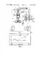
- FIG. 1is a diagram of a portion of a diesel engine including a turbocharger, and test equipment connected thereto for determining the condition of the turbocharger;
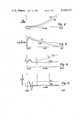
- FIGS. 2 through 5are charts which will be referred to in describing the operation of the apparatus of FIG. 1.
- the exhaust gases from the cylinder 8 of a diesel engine 10are conveyed past an exhaust valve 11 and via a pipe 12 to a turbine motor 14 on a shaft 16 in a turbocharger 20.
- Rotation of the turbine 14 by the exhaust gasesacts through shaft 16 to drive air compressor 22.
- Thiscauses ambient air at inlet 24 to be compressed and delivered via pipe 26 and through an inlet valve 27 to the interior of the cylinder 8.
- Diesel fuelis supplied to the cylinder via a fuel injector 28.
- the test equipment by which the condition of turbocharger 20 is determinedincludes a turbocharger shaft speed sensor 30 having a mechanical linkage over path 32 with the shaft 16, and having a speed-indicating electrical signal output at 34.
- the shaft speed sensor 30may be a tachometer mechanically connected to the shaft 16 if the shaft is externally accessible, or may include an electro-magnetic pick-up constructed in the turbocharger, or may include an electro-magnetic pick-up device positioned on the exterior of the turbine 14 or the compressor 22 to sense the movement of rotor blades therein. In any case, the electrical signal representing the rotational speed of shaft 16 is supplied over line 34 to a computer 36.
- the speed of operation of the diesel engine 10is controlled by an engine speed control unit 40 acting over a mechanical linkage 42 on the fuel injector 28.
- the unit 40is controlled, in turn, by an electrical signal supplied over line 44 from computer 36.
- the engine speed control 40may be a human operator acting on information supplied by computer 36.
- the computer 36operates through engine speed control unit 40 to accelerate and then decelerate the diesel engine 10, and during the deceleration of the engine, receives turbocharger shaft speed information from sensor 30.
- the computeranalyses the turbocharger shaft speed information and supplies a turbocharger condition signal over path 46 to a display device 50, which may be a cathode-ray-tube display unit.
- the display devicedepending on the type selected, may display a characteristic as shown, or may display a number representing the slope of the D/N vs N characteristic, or simply the word "GOOD" or the word "BAD".
- the turbocharger condition testis based on an analysis of the deceleration of the turbocharger shaft after the engine is turned off, rather than on any single shaft speed reading. Because the turbocharger speed tends to "float", to arrive at a balance between power produced by the turbine and power absorbed by the compressor and friction, steady-state speed measurements are of little value. It is possible for the turbocharger to have faults, yet still reach an acceptable steady-state speed. Likewise, minor variations in engine (and accessory) condition can cause large variations in steady-state turbocharger speed. It is the transient performance of the turbocharger which provides the most reliable indication of its performance and condition.
- turbocharger accelerationis the power produced by the turbine (directly related to the available energy in the exhaust).
- the turbine poweris negligible, with the compressor load and friction predominating.
- the compressor pressure ratiois close to 1, and the power absorbed is minimal. Allowing for some error to be introduced during certain phases of operation, the compressor power can be ignored.
- the deceleration force on the turbochargeris considered to be solely due to friction.
- the frictionis almost entirely due to viscous friction in the bearings. The complete analysis of real journal bearing friction can become quite complex; it is sufficient here to simplify the analysis to the following relationship:
- Nturbocharger shaft speed
- K 2constant determined by inertia and torque moment arm
- the retarding forceis composed of two components, F v from viscous friction and F s from sliding friction,
- FIG. 4shows D/N values for a good turbocharger and a bad one.
- D/Nshould be directly proportional to the engine oil viscosity.
- FIG. 4shows D/N values for a good turbocharger and a bad one.
- there is an initial peak in D/Nwhich then decreases to a steady value, independent of speed and proportional to oil viscosity (determined by engine temperature).
- the initial non-linearity and peaking of D/Nis due to compressor loading.
- the turbocharger compressorwill have a positive pressure ratio and be absorbing some power. This results in the previously mentioned error caused by assuming compressor power to be negligible.
- the pressure ratiorapidly drops to near one and the compressor power drops to near zero.
- F sis not equal to zero
- D/Nshould increase with decreasing engine speed, as shown by the dashed curve in FIG. 4.
- the slope of D/N between points t 1 and t 2is then a measure of turbocharger condition (amount of sliding friction). It is apparent that by using the slope instead of the absolute value of D/N, the results are not affected by oil viscosity, a concern when testing a large variety of engines in different operating conditions (oil type and temperature).
- a turbocharger testis initiated by causing the engine 10 to accelerate to a high idle speed and then decelerate to a low idle speed. This may be accomplished by a signal from the computer 36 acting through the engine speed control unit 40 on the fuel injector 28 of the engine.
- the turbocharger shaftalso decelerates from a speed N such as 30,000 rpm to a speed N such as 15,000 rpm, as shown by the chart of FIG. 2.
- the speed of a "bad" turbochargerdecreases more quickly than the speed of a "good” turbocharger because of the higher sliding friction in the "bad" turbocharger.
- the decreasing speed of the turbocharger shaftis continuously sensed by the turbocharger shaft speed sensor 30, and electrical sample representations of the decreasing speed are supplied over line 34 to the computer 36.
- the computeruses each speed information sample (together with the previous speed sample) to calculate the deceleration D between samples as shown by the chart of FIG. 3, and uses the resultant value of D together with the speed sample N to calculate D/N as shown by the chart of FIG. 4, and finally uses the resultant value of D/N and the speed sample N to calculate the slope of D/N, particularly in the intermediate region between times t 1 and t 2 .
- a go-no go threshold value for the absolute value of the D/N slopecan be set to conveniently and positively distinguish good and bad turbochargers.
Landscapes
- Physics & Mathematics (AREA)
- General Physics & Mathematics (AREA)
- Supercharger (AREA)
Abstract
Description
F.sub.v =K.sub.1 μN (1)
D=K.sub.2 F (2)
D=K.sub.2 (F.sub.v +F.sub.s)=K.sub.2 F.sub.v +K.sub.2 F.sub.s (3)
D=K.sub.3 μN+K.sub.2 F.sub.s (4)
D/N=K.sub.3 μ (5)
D/N=K.sub.3 μ+KF.sub.s /N (6)
Claims (2)
Priority Applications (1)
| Application Number | Priority Date | Filing Date | Title |
|---|---|---|---|
| US06/198,457US4334427A (en) | 1980-10-20 | 1980-10-20 | Testing the condition of a turbocharger |
Applications Claiming Priority (1)
| Application Number | Priority Date | Filing Date | Title |
|---|---|---|---|
| US06/198,457US4334427A (en) | 1980-10-20 | 1980-10-20 | Testing the condition of a turbocharger |
Publications (1)
| Publication Number | Publication Date |
|---|---|
| US4334427Atrue US4334427A (en) | 1982-06-15 |
Family
ID=22733465
Family Applications (1)
| Application Number | Title | Priority Date | Filing Date |
|---|---|---|---|
| US06/198,457Expired - LifetimeUS4334427A (en) | 1980-10-20 | 1980-10-20 | Testing the condition of a turbocharger |
Country Status (1)
| Country | Link |
|---|---|
| US (1) | US4334427A (en) |
Cited By (29)
| Publication number | Priority date | Publication date | Assignee | Title |
|---|---|---|---|---|
| US4428227A (en) | 1981-05-19 | 1984-01-31 | Honda Giken Kogyo Kabushiki Kaisha | Intake pipe pressure indicating system for an internal combustion engine of a vehicle |
| US6163254A (en)* | 1999-11-23 | 2000-12-19 | Caterpillar Inc. | Method of avoiding low cycle fatigue failure of turbochargers |
| US6209390B1 (en)* | 1999-05-14 | 2001-04-03 | Larue Gerald Duane | Turbocharger fatigue life monitor |
| DE10300357A1 (en)* | 2002-12-03 | 2004-06-24 | Johann A. Krause Maschinenfabrik Gmbh | Exhaust gas turbocharger testing method |
| EP1312766A3 (en)* | 2001-11-07 | 2004-09-08 | ROLLS-ROYCE plc | An apparatus and method for detecting an impact on a rotor blade |
| US20050274112A1 (en)* | 2004-06-09 | 2005-12-15 | Isuzu Motors Limited | Fatigue failure diagnostic method of turbocharger and fatigue failure diagnostic apparatus for turbocharger |
| US20060196256A1 (en)* | 2005-03-02 | 2006-09-07 | Christian Rohde | Method for the testing of exhaust gas turbochargers |
| US20070078585A1 (en)* | 2005-09-30 | 2007-04-05 | Pomeroy Bruce D | System and method for estimating turbine engine deterioration rate with noisy data |
| US20080236266A1 (en)* | 2007-03-02 | 2008-10-02 | Detroit Diesel Corporation | Method of diagnosing turbochargers for internal combustion engines |
| EP2055905A2 (en) | 2007-02-23 | 2009-05-06 | Mitsubishi Heavy Industries, Ltd. | Power turbine test apparatus |
| US20090293476A1 (en)* | 2008-05-30 | 2009-12-03 | Raymond Geraint Evans | Fuel control system for limiting turbocharger speed |
| JP2009543059A (en)* | 2006-06-30 | 2009-12-03 | インターナショナル エンジン インテレクチュアル プロパティー カンパニー リミテッド ライアビリティ カンパニー | Turbocharger performance certification method and apparatus |
| US20100135773A1 (en)* | 2007-04-16 | 2010-06-03 | Andre Kaufmann | Turbocharger having a device for detecting a malfunction of the turbocharger and a method for detecting such a malfunction |
| US8538626B2 (en) | 2011-09-15 | 2013-09-17 | General Electric Company | Systems and methods for diagnosing an engine |
| US20140107905A1 (en)* | 2011-04-08 | 2014-04-17 | Uwe Kassner | Method for diagnosing a supercharging system of internal combustion engines |
| US8875561B2 (en) | 2011-09-15 | 2014-11-04 | General Electric Company | Systems and methods for diagnosing an engine |
| US8984930B2 (en) | 2011-09-15 | 2015-03-24 | General Electric Company | System and method for diagnosing a reciprocating compressor |
| CN104458238A (en)* | 2014-12-15 | 2015-03-25 | 北京理工大学 | Self-circulating type test bed for turbocharger high-low temperature cycling thermal shock testing |
| US9046050B2 (en) | 2011-09-15 | 2015-06-02 | General Electric Company | Shaft imbalance detection system |
| CN105043779A (en)* | 2015-09-11 | 2015-11-11 | 北京理工大学 | Turbocharger startup and shutdown impact test device |
| US9574965B2 (en) | 2014-06-24 | 2017-02-21 | General Electric Company | System and method of determining bearing health in a rotating machine |
| US9606022B2 (en) | 2012-08-31 | 2017-03-28 | General Electric Company | Systems and methods for diagnosing engine components and auxiliary equipment associated with an engine |
| US9677556B2 (en) | 2012-04-20 | 2017-06-13 | General Electric Company | System and method for a compressor |
| US9897082B2 (en) | 2011-09-15 | 2018-02-20 | General Electric Company | Air compressor prognostic system |
| CN109580231A (en)* | 2018-12-12 | 2019-04-05 | 中国北方发动机研究所(天津) | A kind of pressure shell rotation failure test method of identification diesel engine matching turbocharger |
| US10338580B2 (en) | 2014-10-22 | 2019-07-02 | Ge Global Sourcing Llc | System and method for determining vehicle orientation in a vehicle consist |
| US10464579B2 (en) | 2006-04-17 | 2019-11-05 | Ge Global Sourcing Llc | System and method for automated establishment of a vehicle consist |
| CN112798469A (en)* | 2021-01-19 | 2021-05-14 | 潍柴动力股份有限公司 | A kind of oil viscosity detection method and engine |
| US11131604B2 (en) | 2019-02-21 | 2021-09-28 | Caterpillar Inc. | Turbocharger speed sensor diagnostic tool and method |
Citations (2)
| Publication number | Priority date | Publication date | Assignee | Title |
|---|---|---|---|---|
| US4046003A (en)* | 1976-05-07 | 1977-09-06 | United Technologies Corporation | Engine turbocharger diagnostics |
| US4277830A (en)* | 1979-06-11 | 1981-07-07 | Cummins Engine Company, Inc. | Diagnosis of engine turbocharger performance |
- 1980
- 1980-10-20USUS06/198,457patent/US4334427A/ennot_activeExpired - Lifetime
Patent Citations (2)
| Publication number | Priority date | Publication date | Assignee | Title |
|---|---|---|---|---|
| US4046003A (en)* | 1976-05-07 | 1977-09-06 | United Technologies Corporation | Engine turbocharger diagnostics |
| US4277830A (en)* | 1979-06-11 | 1981-07-07 | Cummins Engine Company, Inc. | Diagnosis of engine turbocharger performance |
Cited By (45)
| Publication number | Priority date | Publication date | Assignee | Title |
|---|---|---|---|---|
| US4428227A (en) | 1981-05-19 | 1984-01-31 | Honda Giken Kogyo Kabushiki Kaisha | Intake pipe pressure indicating system for an internal combustion engine of a vehicle |
| US6209390B1 (en)* | 1999-05-14 | 2001-04-03 | Larue Gerald Duane | Turbocharger fatigue life monitor |
| US6163254A (en)* | 1999-11-23 | 2000-12-19 | Caterpillar Inc. | Method of avoiding low cycle fatigue failure of turbochargers |
| EP1312766A3 (en)* | 2001-11-07 | 2004-09-08 | ROLLS-ROYCE plc | An apparatus and method for detecting an impact on a rotor blade |
| US6932560B2 (en) | 2001-11-07 | 2005-08-23 | Rolls-Royce Plc | Apparatus and method for detecting an impact on a rotor blade |
| DE10300357A1 (en)* | 2002-12-03 | 2004-06-24 | Johann A. Krause Maschinenfabrik Gmbh | Exhaust gas turbocharger testing method |
| US7181959B2 (en)* | 2004-06-09 | 2007-02-27 | Isuzu Motors Limited | Fatigue failure diagnostic method of turbocharger and fatigue failure diagnostic apparatus for turbocharger |
| US20050274112A1 (en)* | 2004-06-09 | 2005-12-15 | Isuzu Motors Limited | Fatigue failure diagnostic method of turbocharger and fatigue failure diagnostic apparatus for turbocharger |
| US7278302B2 (en)* | 2005-03-02 | 2007-10-09 | Johann A. Krause Maschinenfabrik GmbH | Method for the testing of exhaust gas turbochargers |
| US20060196256A1 (en)* | 2005-03-02 | 2006-09-07 | Christian Rohde | Method for the testing of exhaust gas turbochargers |
| US20070078585A1 (en)* | 2005-09-30 | 2007-04-05 | Pomeroy Bruce D | System and method for estimating turbine engine deterioration rate with noisy data |
| US7286923B2 (en)* | 2005-09-30 | 2007-10-23 | General Electric Company | System and method for estimating turbine engine deterioration rate with noisy data |
| US10464579B2 (en) | 2006-04-17 | 2019-11-05 | Ge Global Sourcing Llc | System and method for automated establishment of a vehicle consist |
| CN102607857A (en)* | 2006-06-30 | 2012-07-25 | 万国引擎知识产权有限责任公司 | Turbocharger performance qualification method and apparatus |
| JP2009543059A (en)* | 2006-06-30 | 2009-12-03 | インターナショナル エンジン インテレクチュアル プロパティー カンパニー リミテッド ライアビリティ カンパニー | Turbocharger performance certification method and apparatus |
| EP2038633A4 (en)* | 2006-06-30 | 2010-08-25 | Internat Engine Intellectual C | Turbocharger performance qualification method and apparatus |
| EP2055905A2 (en) | 2007-02-23 | 2009-05-06 | Mitsubishi Heavy Industries, Ltd. | Power turbine test apparatus |
| EP2055905A3 (en)* | 2007-02-23 | 2012-10-31 | Mitsubishi Heavy Industries, Ltd. | Power turbine test apparatus |
| US20080236266A1 (en)* | 2007-03-02 | 2008-10-02 | Detroit Diesel Corporation | Method of diagnosing turbochargers for internal combustion engines |
| US7469577B2 (en) | 2007-03-02 | 2008-12-30 | Detroit Diesel Corporation | Method of diagnosing turbochargers for internal combustion engines |
| US8393852B2 (en)* | 2007-04-16 | 2013-03-12 | Continental Automotive Gmbh | Turbocharger having a device for detecting a malfunction of the turbocharger and a method for detecting such a malfunction |
| US20100135773A1 (en)* | 2007-04-16 | 2010-06-03 | Andre Kaufmann | Turbocharger having a device for detecting a malfunction of the turbocharger and a method for detecting such a malfunction |
| US20090293476A1 (en)* | 2008-05-30 | 2009-12-03 | Raymond Geraint Evans | Fuel control system for limiting turbocharger speed |
| US8061137B2 (en)* | 2008-05-30 | 2011-11-22 | Caterpillar Inc. | Fuel control system for limiting turbocharger speed |
| US20140107905A1 (en)* | 2011-04-08 | 2014-04-17 | Uwe Kassner | Method for diagnosing a supercharging system of internal combustion engines |
| US9897082B2 (en) | 2011-09-15 | 2018-02-20 | General Electric Company | Air compressor prognostic system |
| US8538626B2 (en) | 2011-09-15 | 2013-09-17 | General Electric Company | Systems and methods for diagnosing an engine |
| US8626371B2 (en) | 2011-09-15 | 2014-01-07 | General Electric Company | Systems and methods for diagnosing auxiliary equipment associated with an engine |
| US8626372B2 (en) | 2011-09-15 | 2014-01-07 | General Electric Company | Systems and methods for diagnosing an engine |
| US8875561B2 (en) | 2011-09-15 | 2014-11-04 | General Electric Company | Systems and methods for diagnosing an engine |
| US8984930B2 (en) | 2011-09-15 | 2015-03-24 | General Electric Company | System and method for diagnosing a reciprocating compressor |
| US9046050B2 (en) | 2011-09-15 | 2015-06-02 | General Electric Company | Shaft imbalance detection system |
| US10036335B2 (en) | 2011-09-15 | 2018-07-31 | General Electric Company | Systems and methods for diagnosing an engine |
| US10233920B2 (en) | 2012-04-20 | 2019-03-19 | Ge Global Sourcing Llc | System and method for a compressor |
| US9677556B2 (en) | 2012-04-20 | 2017-06-13 | General Electric Company | System and method for a compressor |
| US9771933B2 (en) | 2012-04-20 | 2017-09-26 | General Electric Company | System and method for a compressor |
| US9606022B2 (en) | 2012-08-31 | 2017-03-28 | General Electric Company | Systems and methods for diagnosing engine components and auxiliary equipment associated with an engine |
| US9574965B2 (en) | 2014-06-24 | 2017-02-21 | General Electric Company | System and method of determining bearing health in a rotating machine |
| US10338580B2 (en) | 2014-10-22 | 2019-07-02 | Ge Global Sourcing Llc | System and method for determining vehicle orientation in a vehicle consist |
| CN104458238A (en)* | 2014-12-15 | 2015-03-25 | 北京理工大学 | Self-circulating type test bed for turbocharger high-low temperature cycling thermal shock testing |
| CN105043779B (en)* | 2015-09-11 | 2018-07-27 | 北京理工大学 | A kind of turbocharger start/stop impact experimental rig |
| CN105043779A (en)* | 2015-09-11 | 2015-11-11 | 北京理工大学 | Turbocharger startup and shutdown impact test device |
| CN109580231A (en)* | 2018-12-12 | 2019-04-05 | 中国北方发动机研究所(天津) | A kind of pressure shell rotation failure test method of identification diesel engine matching turbocharger |
| US11131604B2 (en) | 2019-02-21 | 2021-09-28 | Caterpillar Inc. | Turbocharger speed sensor diagnostic tool and method |
| CN112798469A (en)* | 2021-01-19 | 2021-05-14 | 潍柴动力股份有限公司 | A kind of oil viscosity detection method and engine |
Similar Documents
| Publication | Publication Date | Title |
|---|---|---|
| US4334427A (en) | Testing the condition of a turbocharger | |
| KR101395771B1 (en) | Turbocharger having a device for detecting a malfunction of the turbocharger and a method for detecting such a malfunction | |
| CA1141469A (en) | Diagnosis of engine turbocharger performance | |
| US4046003A (en) | Engine turbocharger diagnostics | |
| CA1115603A (en) | Apparatus for detecting and indicating the occurrence of a gas turbine engine compressor stall | |
| CN101512128A (en) | System and method for detecting impaired operation of a turbocharger of an internal combustion engine | |
| KR20010006535A (en) | method and device for protecting a turbo-supercharger | |
| CA1199728A (en) | Dynamic engine power assessment | |
| CN111811826A (en) | A diesel engine test platform and method for comprehensive performance analysis of cylinder liner and piston ring | |
| US4356725A (en) | Testing the power of a turbocharged internal combustion engine | |
| JP7449889B2 (en) | Supercharger abnormality sign determination device and supercharger abnormality sign determination method | |
| CN115356025A (en) | System and method for testing friction power consumption of turbocharger | |
| JPS6257805B2 (en) | ||
| Frith | The effect of compressor rotor tip crops on turboshaft engine performance | |
| RU2030726C1 (en) | Method of testing turbo-compressor | |
| Shepelev et al. | Increasing the Robustness of Modern Turbocharging Systems Using a Hydraulic Accumulator and Oil Circulation | |
| KR102783436B1 (en) | Simulation test device for performance evaluation of designed impeller | |
| Armstrong et al. | Recent Advancements in Men-Contact Diesel Diagnostics | |
| SU815528A2 (en) | Method of measuring internal combustion engine effective horse-power | |
| RU2118809C1 (en) | Method of diagnostics of gas-turbine engine compressor | |
| Takács | Investigation of the Impact of Future Emission Norms on the Axial Force System in Turbochargers using Measurements and Numerical Methods | |
| JPH051630Y2 (en) | ||
| Frith | The effect of compressor rotor tip crops on turboshaft engine performance | |
| Usai et al. | Time to boost analysis of an advanced boosting system for automotive applications | |
| Žák et al. | Evaluation of experiments on a twin scroll turbocharger turbine for calibration of a complex 1-D model |
Legal Events
| Date | Code | Title | Description |
|---|---|---|---|
| AS | Assignment | Owner name:RCA CORPORATION, A CORP. OF DE., DELAWARE Free format text:ASSIGNMENT OF ASSIGNORS INTEREST;ASSIGNOR:ARMSTRONG LEE R.;REEL/FRAME:003834/0735 Effective date:19801009 | |
| STCF | Information on status: patent grant | Free format text:PATENTED CASE | |
| AS | Assignment | Owner name:MARTIN MARIETTA CORPORATION, MARYLAND Free format text:ASSIGNMENT OF ASSIGNORS INTEREST;ASSIGNOR:GENERAL ELECTRIC COMPANY;REEL/FRAME:007046/0736 Effective date:19940322 | |
| AS | Assignment | Owner name:LOCKHEED MARTIN CORPORATION, MARYLAND Free format text:ASSIGNMENT OF ASSIGNORS INTEREST;ASSIGNOR:MARTIN MARIETTA CORPORATION;REEL/FRAME:008628/0518 Effective date:19960128 | |
| AS | Assignment | Owner name:GENERAL DYNAMICS DEFENSE SYSTEMS, INC., VIRGINIA Free format text:ASSIGNMENT OF ASSIGNORS INTEREST;ASSIGNOR:LOCKHEED MARTIN CORPORATION;REEL/FRAME:009005/0325 Effective date:19970101 |