US4333238A - Coordinate measuring machine - Google Patents
Coordinate measuring machineDownload PDFInfo
- Publication number
- US4333238A US4333238AUS06/136,091US13609180AUS4333238AUS 4333238 AUS4333238 AUS 4333238AUS 13609180 AUS13609180 AUS 13609180AUS 4333238 AUS4333238 AUS 4333238A
- Authority
- US
- United States
- Prior art keywords
- probe
- workpiece
- measurement
- measuring
- determining
- Prior art date
- Legal status (The legal status is an assumption and is not a legal conclusion. Google has not performed a legal analysis and makes no representation as to the accuracy of the status listed.)
- Expired - Lifetime
Links
Images


Classifications
- G—PHYSICS
- G01—MEASURING; TESTING
- G01B—MEASURING LENGTH, THICKNESS OR SIMILAR LINEAR DIMENSIONS; MEASURING ANGLES; MEASURING AREAS; MEASURING IRREGULARITIES OF SURFACES OR CONTOURS
- G01B11/00—Measuring arrangements characterised by the use of optical techniques
- G01B11/002—Measuring arrangements characterised by the use of optical techniques for measuring two or more coordinates
- G01B11/005—Measuring arrangements characterised by the use of optical techniques for measuring two or more coordinates coordinate measuring machines
- G—PHYSICS
- G01—MEASURING; TESTING
- G01B—MEASURING LENGTH, THICKNESS OR SIMILAR LINEAR DIMENSIONS; MEASURING ANGLES; MEASURING AREAS; MEASURING IRREGULARITIES OF SURFACES OR CONTOURS
- G01B21/00—Measuring arrangements or details thereof, where the measuring technique is not covered by the other groups of this subclass, unspecified or not relevant
- G01B21/02—Measuring arrangements or details thereof, where the measuring technique is not covered by the other groups of this subclass, unspecified or not relevant for measuring length, width, or thickness
- G01B21/04—Measuring arrangements or details thereof, where the measuring technique is not covered by the other groups of this subclass, unspecified or not relevant for measuring length, width, or thickness by measuring coordinates of points
- G01B21/045—Correction of measurements
- G—PHYSICS
- G01—MEASURING; TESTING
- G01B—MEASURING LENGTH, THICKNESS OR SIMILAR LINEAR DIMENSIONS; MEASURING ANGLES; MEASURING AREAS; MEASURING IRREGULARITIES OF SURFACES OR CONTOURS
- G01B7/00—Measuring arrangements characterised by the use of electric or magnetic techniques
- G01B7/004—Measuring arrangements characterised by the use of electric or magnetic techniques for measuring coordinates of points
- G01B7/008—Measuring arrangements characterised by the use of electric or magnetic techniques for measuring coordinates of points using coordinate measuring machines
- G01B7/012—Contact-making feeler heads therefor
- G—PHYSICS
- G01—MEASURING; TESTING
- G01P—MEASURING LINEAR OR ANGULAR SPEED, ACCELERATION, DECELERATION, OR SHOCK; INDICATING PRESENCE, ABSENCE, OR DIRECTION, OF MOVEMENT
- G01P15/00—Measuring acceleration; Measuring deceleration; Measuring shock, i.e. sudden change of acceleration
- G01P15/02—Measuring acceleration; Measuring deceleration; Measuring shock, i.e. sudden change of acceleration by making use of inertia forces using solid seismic masses
- G01P15/08—Measuring acceleration; Measuring deceleration; Measuring shock, i.e. sudden change of acceleration by making use of inertia forces using solid seismic masses with conversion into electric or magnetic values
- G01P15/09—Measuring acceleration; Measuring deceleration; Measuring shock, i.e. sudden change of acceleration by making use of inertia forces using solid seismic masses with conversion into electric or magnetic values by piezoelectric pick-up
Definitions
- This inventionrelates to coordinate measuring machines having structure supporting a probe for movement relative to a workpiece to be measured and relative to a means for continually measuring the position of the probe relative to a datum, the probe having means for generating a signal when having a predetermined relationship with a proximate surface of the workpiece.
- the probeis moved toward a said surface and the signal is used to determine the output of the measuring means at the instant when the probe attains said predetermined relationship thereby to determine the position of said surface relative to said datum.
- a method of determining a measurement of a workpiece on a machinecomprising structure supporting a probe for movement relative to a workpiece to be measured and relative to a means for continually measuring the position of the probe relative to a datum, the probe having means for generating a measuring signal when having a predetermined relationship with a proximate surface of the workpiece; the method comprising:
- a machine for determining a measurement of a workpiececomprising;
- the dynamic deflectionmay be determined by sensing any parameter on the machine which is affected by a change of speed of the probe.
- Measurements of a said parameterare converted into measures of corresponding displacements of the probe from the position which it would have when at rest or at a uniform speed, and the displacement measure is then added to or subtracted from, as the case may require, the actual measurement recorded by the measuring means.
- Said parametermay be acceleration as measured by, for example, an accelerometer on a moving part of the machine, a strain gauge on a moving or stationary part of the machine, or a torque meter on a shaft, or a current meter in a motor, used for driving the machine.
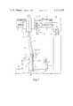
- FIG. 1is an elevation of the machine.
- FIG. 2is a diagram of the system.
- FIG. 3is an enlarged part of FIG. 1 showing details of a probe and of an accelerometer.
- FIG. 4is a velocity diagram.
- the machinecomprises a probe 10 supported for movement in the X, Y and Z directions of the orthogonal coordinate system.
- the probe 10is secured to the bottom end of a vertically extending elongate member or quill 11 supported for movement in the Z direction by a bearing 12 which is integral with a carriage 13 supported for movement in the X direction by a beam 14.
- the latteris supported for movement in the Y direction by a track 15 mounted on a table 16.
- the probe 10has a stylus 17 having a spherical sensing end 27 whereby to engage a workpiece 8 to be measured.
- the member 11which under steady conditions lies on a centre line 11A, is bent by the inertia of the member 11 to lie on a centre line 11B.
- the membermay be regarded as a cantilever supported at the bearing 12 and deflecting relative to that bearing and to the carriage 13.
- the sensing end 27, which under steady conditions has a position 27Atherefore takes up a position 27B spaced from the position 27A by a deflection DX shown to an exaggerated extent.
- the actual dimension of the deflection DXmay be of the order of a few micrometer.
- the sensing end 27therefore engages the workpiece later than it would have done if there had been no deflection of the member 11. It is assumed that the acceleration has taken place at a uniform rate so that the speed of the probe increases quadratically to the distance travelled and the deflection DX has remained unchanged right up to the time of engagement with the workpiece. At the time of such engagement the sensing head 24 has a position 24B in advance of a position 24A which it would have under steady conditions. The distance X2, measured by the reading head is therefore greater than the distance X1 by the amount DX.
- the probe 10itself may be of any kind having means for outputting a signal 37 when the probe, more specifically a sensing element of the probe, has a predetermined relationship with the workpiece.
- the sensing elementis the stylus 17 and its sensing end 27, and the signal 37 is produced by electrical contacts 38 (FIG. 3) whereby the stylus 17 is supported on a housing 36.
- the contactschange the state of an electrical circuit when a force acting on the stylus changes the state of the contacts.
- the signal 37is used to stop the motor 20 and initiate the next measuring operation. Inasmuch as the probe overruns the measuring point by a small amount this is accommodated by tilting of the stylus on the contacts.
- the signal 37is also used to transfer the instantaneous reading of the counter 26X to a main store 28 of a computer 29 used for processing the measurements made by the machine.
- the inventionprovides a means for generating a signal showing that the distance DX is in excess of an allowable minimum.
- the accelerometer 30comprises a known arrangement of piezoelectric crystals 31 connected between a base 32 and a free mass 33, Three outputs 34X, 34Y, 34Z, also collectively referred to as the outputs 34, are derived from the crystals to carry the electric currents generated in respect of inertia forces acting on the mass 33 in the X, Y and Z direction respectively.
- the accelerometer 30is mounted in a housing 35 directly connected between the member 11 and the housing 36 of the probe.
- the outputs 34are connected to respective threshold amplifiers 38 (only one shown in FIG. 2) whose output 39 is proportional to the magnitude of the signals 34 when the latter exceed a certain predetermined threshold corresponding to an acceptable maximum of deflection of the member 11.
- the outputs 39may be used to act on a switch 40 to inhibit the transfer of the counter output to the store 28 and to output a signal 41 used to indicate that the measuring operation should be repeated at a lower speed.
- This use of the accelerometer outputapplies especially if the motor 20 is operated by the operator applying manual force to the member 11.
- the following systemis preferred.
- the signal 34is connected to a digitiser 42 which converts the varying level of the signal 34 into a corresponding binary signal 43.
- the signal 43is taken through a buffer store 44 and decoder 45 whose output 46 is an address of a correction store 47.
- the latter storecontains a list of actual values DX(n) of the deflection DX for corresponding values of the signal 34X.
- the signal 37is connected to the buffer store 44 to transfer the value held at the instant of the signal 37 through the decoder 45 into the store 47 which responds by outputting the value DZ(n) present in the address concerned to a subtractor 48.
- the latteris connected between the counter 26X and the store 28 and is adapted to form the difference X2-DX(n) which difference is of course the true value of the distance X1.
- the different values of DX(n) held in the store 47are found by a calibration process. This involves moving the carriage 13 to bring the probe 10 into engagement with a test piece, say the workpiece 8. At first the carriage 13 is driven at the same slow uniform speed as that used for setting the zero of the counter 26X at the datum block 22. This establishes a base reading X2a at the counter 26 which should be equal to the distance X1. Thereafter, the carriage run is repeated a number of times at progressively increased accelerations. For each run of the carriage the output X2n of the counter 26X at the instant of the signal 37 is recorded in the store 28 against the content of the buffer store 44.
- the systemhas been described with reference to the X dimension. A similar system is provided for the Y dimension. In view of the stiffness of the member 11 in the Z dimension, the system would not normally be required for that dimension but the machine would of course have, for the Z dimension, a scale, reading head and counter similar to those described for the X dimension.
- the counter for the Z dimensionis shown at 26Z in FIG. 2.
- FIG. 4there is shown a curve showing the acceleration of the probe 10 between points A and B.
- the accelerationmay be uniform to raise the speed of the probe to a maximum at the correspondingly high rate.
- the probeOn attaining the maximum at point B, this being the highest speed at which the motor 20 can be driven, the probe initially oscillates due to vibration of the member 11 where projecting from the bearing 12. The oscillations die down and the probe speed attains a uniform value, say, at a point C.
- the accelerometer 30will of course respond to the vibrations and act to correct the reading accordingly.
- the accelerometermay be used to inhibit the reading by means of the switch 40 for as long as the excursions of the oscillations are above an acceptable minimum.
- the accelerometermay be mounted on the carriage 13 and a correction routine similar to that described may be based on the latter position of the accelerometer.
- a strain gaugemay be used at any position subject to stress in response to the acceleration of the probe.
- the computer 29is an electronic digital computer and the subtractor 48 may exist in hard-wired or in software form.
Landscapes
- Physics & Mathematics (AREA)
- General Physics & Mathematics (AREA)
- Length Measuring Devices With Unspecified Measuring Means (AREA)
- A Measuring Device Byusing Mechanical Method (AREA)
- Measurement Of Length, Angles, Or The Like Using Electric Or Magnetic Means (AREA)
Abstract
Description
This invention relates to coordinate measuring machines having structure supporting a probe for movement relative to a workpiece to be measured and relative to a means for continually measuring the position of the probe relative to a datum, the probe having means for generating a signal when having a predetermined relationship with a proximate surface of the workpiece. In operation, the probe is moved toward a said surface and the signal is used to determine the output of the measuring means at the instant when the probe attains said predetermined relationship thereby to determine the position of said surface relative to said datum.
To speed up the measuring operations it is the practice to move the probe rapidly from one to the next of the surfaces to be measured. However, this practice is limited by dynamic deflection of the support structure. In other words, if, at the instant when said signal is generated, the probe is subject to acceleration or deceleration, the measurement is different from what it would be if the probe had a constant velocity. If this difference is greater than a given tolerance the measurement is useless. It is an object of this invention to overcome or reduce this difficulty.
According to this invention there is provided a method of determining a measurement of a workpiece on a machine comprising structure supporting a probe for movement relative to a workpiece to be measured and relative to a means for continually measuring the position of the probe relative to a datum, the probe having means for generating a measuring signal when having a predetermined relationship with a proximate surface of the workpiece; the method comprising:
(a) moving the probe toward said surface,
(b) determining dynamic deflection of said structure at the instant of said signal, and
(c) adjusting the output of the measuring means to take account of said deflection.
Also according to this invention there is provided a machine for determining a measurement of a workpiece comprising;
(a) a probe having means for generating a measuring signal when having a predetermined relationship to a proximate surface of the workpiece,
(b) structure supporting the probe for movement relative to the workpiece,
(c) means for continually measuring the position of the probe during said movement relative to a given datum,
(d) means for determining dynamic deflection of said structure at the instant of said signal, and
(e) means responsive to said deflection for adjusting the output of the measuring means to take account of said deflection.
The dynamic deflection may be determined by sensing any parameter on the machine which is affected by a change of speed of the probe.
Measurements of a said parameter are converted into measures of corresponding displacements of the probe from the position which it would have when at rest or at a uniform speed, and the displacement measure is then added to or subtracted from, as the case may require, the actual measurement recorded by the measuring means.
Said parameter may be acceleration as measured by, for example, an accelerometer on a moving part of the machine, a strain gauge on a moving or stationary part of the machine, or a torque meter on a shaft, or a current meter in a motor, used for driving the machine.
An example of a machine and a system according to this invention will now be described with reference to the accompanying drawings wherein:
FIG. 1 is an elevation of the machine.
FIG. 2 is a diagram of the system.
FIG. 3 is an enlarged part of FIG. 1 showing details of a probe and of an accelerometer.
FIG. 4 is a velocity diagram.
Referring to FIG. 1, the machine comprises aprobe 10 supported for movement in the X, Y and Z directions of the orthogonal coordinate system. To this end theprobe 10 is secured to the bottom end of a vertically extending elongate member orquill 11 supported for movement in the Z direction by abearing 12 which is integral with acarriage 13 supported for movement in the X direction by abeam 14. The latter is supported for movement in the Y direction by atrack 15 mounted on a table 16. Theprobe 10 has astylus 17 having aspherical sensing end 27 whereby to engage aworkpiece 8 to be measured. Let it be assumed that a measurement has to be carried out in the X direction and that it is intended to determine a distance X1 between aface 21 of adatum block 22 and aface 23 of theworkpiece 8. This operation involves moving thecarriage 13 in the X direction along thetrack 14 by means of ascrew 19 rotated by amotor 20 secured to one end of thebeam 14. The actual measuring is carried out by an opto-electronic reading head 24 secured to thecarriage 13 and movable together therewith along ascale 25 secured to thebeam 14. The output of the reading head is read by acounter 26X (FIG. 2).
It will be understood that similar screw and motor devices (not shown) are provided for moving thequill 11 through thebearing 12 and for moving thebeam 14 along thetrack 15 and that theprobe 10 is at first moved by the latter devices into the Y and Z directions so that the X measurement is taken at the desired YZ location. Also, themotor 20 is at first operated to place thesensing end 27 against thedatum surface 21 and that thecounter 26X is set to zero in response to asignal 37 output by the probe at the instant of engagement between thesensing end 27 and thesurface 21. Special care is taken to ensure that the probe is moved at a slow uniform datum speed against thesurface 21 to avoid falsification of the zero setting by inertia effects.
Similar zeroing operations are of course also carried out in respect of the Y and Z dimensions. Each such operation usually involves halting the probe immediately after the measurement is taken and accelerating the probe to the next measuring point. After such zeroing the machine is ready for all measuring operations pertaining to that zero, and it is understood that the one measurement to be described is the first of many, often hundreds, of such operations which have to be carried out on a complex workpiece. To make this work economical, the operations have to be carried out in rapid succession, but the more rapidly the movable members are moved, the greater is the possibility of the measurements being falsified by inertia effects. This will now be described in detail.
As themotor 20 is driven to accelerate the carriage in the X direction from the zero position or from any one position of rest, themember 11, which under steady conditions lies on acentre line 11A, is bent by the inertia of themember 11 to lie on acentre line 11B. In this connection, the member may be regarded as a cantilever supported at thebearing 12 and deflecting relative to that bearing and to thecarriage 13. The sensingend 27, which under steady conditions has aposition 27A therefore takes up a position 27B spaced from theposition 27A by a deflection DX shown to an exaggerated extent. The actual dimension of the deflection DX may be of the order of a few micrometer. The sensingend 27 therefore engages the workpiece later than it would have done if there had been no deflection of themember 11. It is assumed that the acceleration has taken place at a uniform rate so that the speed of the probe increases quadratically to the distance travelled and the deflection DX has remained unchanged right up to the time of engagement with the workpiece. At the time of such engagement the sensinghead 24 has a position 24B in advance of aposition 24A which it would have under steady conditions. The distance X2, measured by the reading head is therefore greater than the distance X1 by the amount DX.
Theprobe 10 itself may be of any kind having means for outputting asignal 37 when the probe, more specifically a sensing element of the probe, has a predetermined relationship with the workpiece. In the present example the sensing element is thestylus 17 and itssensing end 27, and thesignal 37 is produced by electrical contacts 38 (FIG. 3) whereby thestylus 17 is supported on ahousing 36. The contacts change the state of an electrical circuit when a force acting on the stylus changes the state of the contacts. Thesignal 37 is used to stop themotor 20 and initiate the next measuring operation. Inasmuch as the probe overruns the measuring point by a small amount this is accommodated by tilting of the stylus on the contacts. Thesignal 37 is also used to transfer the instantaneous reading of thecounter 26X to amain store 28 of acomputer 29 used for processing the measurements made by the machine.
As described so far the machine is known or does not form part of this invention. It will be clear that the accelerations at which such a machine can be operated are limited by the above deflections.
To overcome the above inertia effects the invention provides a means for generating a signal showing that the distance DX is in excess of an allowable minimum. In the present example this is done by anaccelerometer 30 provided in or adjacent theprobe 10. As shown in FIG. 3, theaccelerometer 30 comprises a known arrangement ofpiezoelectric crystals 31 connected between abase 32 and afree mass 33, Threeoutputs outputs 34, are derived from the crystals to carry the electric currents generated in respect of inertia forces acting on themass 33 in the X, Y and Z direction respectively. Theaccelerometer 30 is mounted in ahousing 35 directly connected between themember 11 and thehousing 36 of the probe.
Theoutputs 34 are connected to respective threshold amplifiers 38 (only one shown in FIG. 2) whoseoutput 39 is proportional to the magnitude of thesignals 34 when the latter exceed a certain predetermined threshold corresponding to an acceptable maximum of deflection of themember 11.
Theoutputs 39 may be used to act on aswitch 40 to inhibit the transfer of the counter output to thestore 28 and to output asignal 41 used to indicate that the measuring operation should be repeated at a lower speed. This use of the accelerometer output applies especially if themotor 20 is operated by the operator applying manual force to themember 11. However, insofar as the machine is operated by a computer programme the following system is preferred.
Thesignal 34 is connected to adigitiser 42 which converts the varying level of thesignal 34 into a correspondingbinary signal 43. Thesignal 43 is taken through abuffer store 44 anddecoder 45 whoseoutput 46 is an address of acorrection store 47. The latter store contains a list of actual values DX(n) of the deflection DX for corresponding values of thesignal 34X. Thesignal 37 is connected to thebuffer store 44 to transfer the value held at the instant of thesignal 37 through thedecoder 45 into thestore 47 which responds by outputting the value DZ(n) present in the address concerned to asubtractor 48. The latter is connected between thecounter 26X and thestore 28 and is adapted to form the difference X2-DX(n) which difference is of course the true value of the distance X1.
The different values of DX(n) held in thestore 47 are found by a calibration process. This involves moving thecarriage 13 to bring theprobe 10 into engagement with a test piece, say theworkpiece 8. At first thecarriage 13 is driven at the same slow uniform speed as that used for setting the zero of thecounter 26X at thedatum block 22. This establishes a base reading X2a at the counter 26 which should be equal to the distance X1. Thereafter, the carriage run is repeated a number of times at progressively increased accelerations. For each run of the carriage the output X2n of thecounter 26X at the instant of thesignal 37 is recorded in thestore 28 against the content of thebuffer store 44. The differences X2n-X2a=DXn for the different values of X2n are then produced and are entered into thestore 47 at the addresses corresponding to the outputs of thebuffer store 44 anddecoder 45. These calibrations of the machine can be carried out readily with the aid of thecomputer 29.
The system has been described with reference to the X dimension. A similar system is provided for the Y dimension. In view of the stiffness of themember 11 in the Z dimension, the system would not normally be required for that dimension but the machine would of course have, for the Z dimension, a scale, reading head and counter similar to those described for the X dimension. The counter for the Z dimension is shown at 26Z in FIG. 2.
Reverting to the calibration of the machine, different values of DX(n) are produced at different regions of the coordinate field above the table 16 because the deflection DX is the greater the further theprobe 10 is from thebearing 12, i.e. the greater the unsupported length of themember 11. Therefore the machine is calibrated for different heights Z1 (FIG. 1) of thesensing end 27 above the surface of the table 16. To this end thecounter 26Z (FIG. 2) is connected through a dividingcircuit 49 to produce acorrect signal 50 at intervals of, say, 15 cm during movement of the sensing end from its lowest to its highest position above the table 16. The calibration is carried out at every one of those intervals and thesignal 50 is used to work amultiplexer 51 to direct thedecoder output 46 to the appropriate part of thestore 47.
Referring to FIG. 4, there is shown a curve showing the acceleration of theprobe 10 between points A and B. At this time the acceleration may be uniform to raise the speed of the probe to a maximum at the correspondingly high rate. On attaining the maximum at point B, this being the highest speed at which themotor 20 can be driven, the probe initially oscillates due to vibration of themember 11 where projecting from thebearing 12. The oscillations die down and the probe speed attains a uniform value, say, at a point C. Theaccelerometer 30 will of course respond to the vibrations and act to correct the reading accordingly. Alternatively the accelerometer may be used to inhibit the reading by means of theswitch 40 for as long as the excursions of the oscillations are above an acceptable minimum.
It will be appreciated that, instead of being mounted at the probe, the accelerometer may be mounted on thecarriage 13 and a correction routine similar to that described may be based on the latter position of the accelerometer. Instead of using an accelerometer, a strain gauge may be used at any position subject to stress in response to the acceleration of the probe.
The above described calibration of the machine involved measuring the displacement of the probe for different accelerations. It will be appreciated that the displacement can be calculated by thecomputer 29 on the basis of the acceleration and of known deflection formulae.
Thecomputer 29 is an electronic digital computer and thesubtractor 48 may exist in hard-wired or in software form.
Claims (3)
1. A method of determining a measurement of a workpiece on a machine comprising a probe, structure supporting said probe for flexile and translational movement relative to a workpiece to be measured and relative to a means for continually measuring the position of the probe relative to a datum, the probe having means for generating a signal when having a predetermined relationship with a proximate surface of the workpiece; said method comprising the steps of:
(a) moving said probe toward said surface;
(b) determining the output of said measuring means at the instant said signal is generated thereby defining the measured position of said probe;
(c) determining the deflection of said structure at said instant thereby defining the difference between the measured and the actual positions of said probe; and
(d) subtracting said difference to said output of the measuring means to establish a measure of the actual position of said probe.
2. A machine for determining a measurement of a workpiece comprising:
(a) a probe having means for generating a signal when having a predetermined relationship to a proximate surface of said workpiece;
(b) structure supporting said probe for flexile and translational movement relative to said workpiece;
(c) means for continually measuring the position of said probe, during said translational movement thereof, relative to a datum;
(d) means for determining the output of said measuring means at the instant said signal is generated thereby defining the measured position of said probe;
(e) means for determining the deflection of said structure during said flexile movement thereof, at the instant said signal is generated thereby defining the difference between said measured and actual positions of said probe; and
(f) means for subtracting said difference to said output of the measuring means to establish a measure of the actual position of said probe.
3. A machine for determining a measurement of a workpiece, comprising
(a) an elongate member;
(b) a guide supporting said member at one end thereof for motion in the direction perpendicular to the length of said member, the other end of said member being free;
(c) a stylus provided at the free end of said member for engagement with said workpiece;
(d) means provided at said one end of said member for continually measuring said motion and thereby continually determining a measurement of the position of said stylus relative to a datum, said member being subject to deflection from a rest position due to acceleration during said motion whereby an error may occur between the measurement as determined by the measuring means and the actual position of said stylus;
(e) means for measuring said acceleration;
(f) means for determining a measurement of said deflection responsive to a measurement of said acceleration; and
(g) means for subtracting said deflection measurement to said position measurement in the sense of compensating for said error.
Applications Claiming Priority (2)
| Application Number | Priority Date | Filing Date | Title |
|---|---|---|---|
| GB7911329 | 1979-03-30 | ||
| GB1711329AGB2045437B (en) | 1979-03-30 | 1979-03-30 | Coordinate measuring machine |
Publications (1)
| Publication Number | Publication Date |
|---|---|
| US4333238Atrue US4333238A (en) | 1982-06-08 |
Family
ID=10504253
Family Applications (1)
| Application Number | Title | Priority Date | Filing Date |
|---|---|---|---|
| US06/136,091Expired - LifetimeUS4333238A (en) | 1979-03-30 | 1980-03-31 | Coordinate measuring machine |
Country Status (4)
| Country | Link |
|---|---|
| US (1) | US4333238A (en) |
| JP (1) | JPS55154408A (en) |
| DE (1) | DE3011003C2 (en) |
| GB (1) | GB2045437B (en) |
Cited By (71)
| Publication number | Priority date | Publication date | Assignee | Title |
|---|---|---|---|---|
| US4413422A (en)* | 1980-11-10 | 1983-11-08 | Kitamura Machinery Co. Ltd. | Apparatus for detecting the position of a machine tool spindle |
| US4603487A (en)* | 1985-11-22 | 1986-08-05 | Mitsubishi Jukogyo Kabushiki Kaisha | Method of compensating a profiling direction of a profiling machine |
| US4612622A (en)* | 1983-07-12 | 1986-09-16 | United Technologies Corporation | Probe for coordinate measuring machine |
| US4612709A (en)* | 1984-07-20 | 1986-09-23 | Siemens Aktiengesellschaft | Apparatus for measuring positional movement of a numerically controlled machine tool |
| US4651426A (en)* | 1984-10-10 | 1987-03-24 | Mauser-Werke Oberndorf Gmbh | Portal type coordinate measuring machine |
| US4702013A (en)* | 1984-12-17 | 1987-10-27 | Renishaw Plc | Probe for sensing contact via acceleration |
| US4780961A (en)* | 1986-11-10 | 1988-11-01 | Shelton Russell S | Probe assembly and circuit for measuring machine |
| US4782598A (en)* | 1985-09-19 | 1988-11-08 | Digital Electronic Automation, Inc. | Active error compensation in a coordinate measuring machine |
| US4799170A (en)* | 1985-03-19 | 1989-01-17 | Mitutoyo Mfg. Co. Ltd. | Method of measuring by coordinate measuring instrument |
| US4800652A (en)* | 1987-09-25 | 1989-01-31 | The Timken Company | Machine for measuring generally circular objects in cylindrical coordinates |
| WO1989008817A1 (en)* | 1988-03-10 | 1989-09-21 | Nawsir Inc. | Contact sensing system |
| US4910446A (en)* | 1986-06-14 | 1990-03-20 | Renishaw Plc | Coordinate positioning apparatus |
| US4924715A (en)* | 1988-03-10 | 1990-05-15 | Nawsir Inc. | Contact sensing system |
| US4991304A (en)* | 1987-06-11 | 1991-02-12 | Renishaw | Workpiece inspection method |
| US4997369A (en)* | 1988-12-30 | 1991-03-05 | Michael Knopfmacher | Apparatus for digitizing a three-dimensional surface |
| US5048194A (en)* | 1987-12-05 | 1991-09-17 | Renishaw Plc | Position sensing probe |
| US5063685A (en)* | 1988-09-02 | 1991-11-12 | Renishaw Plc | Tape scale applicator |
| US5138563A (en)* | 1990-01-19 | 1992-08-11 | Carl-Zeiss-Stiftung | Method and apparatus to correct for gravitational sag in the articulated mounting of a probe in a coordinate-measuring machine |
| US5430948A (en)* | 1993-07-12 | 1995-07-11 | Vander Wal, Iii; H. James | Coordinate measuring machine certification system |
| EP0684447A2 (en) | 1994-05-27 | 1995-11-29 | Carl Zeiss | Procedure for coördinate measuring on workpieces |
| US5517124A (en)* | 1989-07-26 | 1996-05-14 | Extrude Hone Corporation | Stylus probe for measuring workpiece surface characteristics |
| EP0657715A3 (en)* | 1993-12-11 | 1996-11-20 | Zeiss Carl | Correction procedure of vibration dependant measurement errors in coördinate measuring machines. |
| US5594668A (en)* | 1994-10-13 | 1997-01-14 | Carl-Zeiss-Stiftung | Method for correcting coordinate measurement on workpieces based on bending characteristics |
| WO1997013117A1 (en)* | 1995-10-04 | 1997-04-10 | Shen Yin Lin | Method of improving accuracy of touch trigger probe |
| EP0684448A3 (en)* | 1994-05-27 | 1997-05-07 | Zeiss Carl | Procedure for coordinate measuring on workpieces. |
| US5737244A (en)* | 1995-08-11 | 1998-04-07 | Carl-Zeiss-Stiftung | Coordinate measuring apparatus having a control which drives the probe head of the apparatus in accordance with desired data |
| US5777562A (en)* | 1996-08-19 | 1998-07-07 | Hoffman; David J. | Centering device and method for centering |
| US5778549A (en)* | 1995-09-19 | 1998-07-14 | Deutsche Forschungsanstalt Fur Luft-Und Raumfahrt E.V. | Correcting measurement errors |
| US5895442A (en)* | 1995-10-20 | 1999-04-20 | Carl-Zeiss-Stiftung | Method for making coordinate measurements on a workpiece |
| EP0974882A2 (en)* | 1998-07-22 | 2000-01-26 | Renishaw plc | Method of and apparatus for reducing vibrations on probes carried by coordinate measuring machines |
| US6044569A (en)* | 1997-02-10 | 2000-04-04 | Mitutoyo Corporation | Measuring method and measuring instrument |
| WO2002004883A1 (en)* | 2000-07-06 | 2002-01-17 | Renishaw Plc | Method of and apparatus for correction of coordinate measurement errors due to vibrations in coordinate measuring machines (cmms) |
| GB2367898A (en)* | 2000-06-13 | 2002-04-17 | Mitutoyo Corp | Surface texture measuring machine and method of correcting a measured value for the machine |
| EP1158269A3 (en)* | 2000-05-23 | 2002-06-26 | Carl Zeiss | Correction method for coordinate measuring machines |
| EP1241436A1 (en)* | 2001-03-14 | 2002-09-18 | Brown & Sharpe Tesa S.A. | Coordinate measuring machine and method for introducing a command to change the measurement mode in this machine |
| US6470587B1 (en) | 1999-07-09 | 2002-10-29 | Vought Aircraft Industries, Inc. | Method and system for part measurement and verification |
| FR2829571A1 (en)* | 2001-09-11 | 2003-03-14 | Ms Mesure | Three dimensional digital metrology measurement of objects using a micro-machine, uses contact and/or laser non contact at end of rod linked to three dimensional positioning system |
| US6546643B2 (en)* | 2000-02-15 | 2003-04-15 | Carl-Zeiss-Stiftung | Articulated device for the probe head of a coordinate measuring apparatus |
| US20030191603A1 (en)* | 2002-02-14 | 2003-10-09 | Simon Raab | Portable coordinate measurement machine with integrated line laser scanner |
| US20040111908A1 (en)* | 2002-02-14 | 2004-06-17 | Simon Raab | Method for improving measurement accuracy of a protable coordinate measurement machine |
| US20050016008A1 (en)* | 2002-02-14 | 2005-01-27 | Simon Raab | Method for providing sensory feedback to the operator of a portable measurement machine |
| US6952882B2 (en) | 2002-02-14 | 2005-10-11 | Faro Technologies, Inc. | Portable coordinate measurement machine |
| US20060016086A1 (en)* | 2002-02-14 | 2006-01-26 | Simon Raab | Portable coordinate measurement machine |
| US20060053648A1 (en)* | 2002-10-29 | 2006-03-16 | Koninklijke Philips Electronics N.V. | Coordinate measuring device and a method for measuring the position of an object |
| US20060129349A1 (en)* | 2002-02-14 | 2006-06-15 | Simon Raab | Portable coordinate measurement machine with integrated line laser scanner |
| WO2006114603A2 (en) | 2005-04-26 | 2006-11-02 | Renishaw Plc | Probe calibration |
| GB2425840A (en)* | 2005-04-13 | 2006-11-08 | Renishaw Plc | Error correction of workpiece measurements |
| US20070051179A1 (en)* | 2003-11-13 | 2007-03-08 | Renishaw Plc | Method of error compensation |
| US20070228592A1 (en)* | 2006-04-03 | 2007-10-04 | Stratasys, Inc. | Auto tip calibration in an extrusion apparatus |
| US20070294045A1 (en)* | 2002-02-14 | 2007-12-20 | Faro Technologies, Inc. | Portable coordinate measurement machine with integrated line laser scanner |
| WO2009001385A1 (en)* | 2007-06-28 | 2008-12-31 | Hexagon Metrology S.P.A. | Method for determining dynamic errors in a measuring machine |
| US20090099803A1 (en)* | 2005-06-15 | 2009-04-16 | Renishaw Plc | Method Of Determining Measurement Probe Orientation |
| US20090187373A1 (en)* | 2002-02-14 | 2009-07-23 | Faro Technologies, Inc. | Portable coordinate measurement machine with integrated line laser scanner |
| WO2009112819A3 (en)* | 2008-03-11 | 2009-11-05 | Renishaw Plc | Touch trigger measurement probe |
| US20100250178A1 (en)* | 2009-03-25 | 2010-09-30 | Mitutoyo Corporation | Corrected ball diameter calculating method and form measuring instrument |
| CN101166953B (en)* | 2005-04-26 | 2010-12-15 | 瑞尼斯豪公司 | Probe calibration |
| US20100325907A1 (en)* | 2009-06-30 | 2010-12-30 | Hexagon Metrology Ab | Coordinate measurement machine with vibration detection |
| USRE42082E1 (en) | 2002-02-14 | 2011-02-01 | Faro Technologies, Inc. | Method and apparatus for improving measurement accuracy of a portable coordinate measurement machine |
| US20110192044A1 (en)* | 2010-02-05 | 2011-08-11 | Mitutoyo Corporation | Coordinate measuring machine |
| EP2410291A1 (en)* | 2010-07-23 | 2012-01-25 | Mitutoyo Corporation | Profile Measuring Instrument |
| US20130041497A1 (en)* | 2010-04-20 | 2013-02-14 | Carl Zeiss Industrielle Messtechnik Gmbh | Operation of a coordinate measuring machine or a machine tool |
| CN102947671A (en)* | 2010-04-23 | 2013-02-27 | 卡尔蔡司工业测量技术有限公司 | Method for measuring the coordinates of workpieces on a coordinate-measuring device |
| US9151633B2 (en) | 1998-01-27 | 2015-10-06 | Steven M. Hoffberg | Mobile communication device for delivering targeted advertisements |
| US9205690B2 (en) | 2012-03-16 | 2015-12-08 | Stratasys, Inc. | Automated calibration method for additive manufacturing system, and method of use thereof |
| CN105136039A (en)* | 2015-10-12 | 2015-12-09 | 北方民族大学 | Novel optical arm amplification type one-dimensional linear measuring head |
| US20180172971A1 (en)* | 2016-12-19 | 2018-06-21 | Novartis Ag | Systems and methods for active vibration reduction of a surgical microscope |
| US10361802B1 (en) | 1999-02-01 | 2019-07-23 | Blanding Hovenweep, Llc | Adaptive pattern recognition based control system and method |
| US10399326B2 (en)* | 2015-10-30 | 2019-09-03 | Stratasys, Inc. | In-situ part position measurement |
| CN112068048A (en)* | 2019-06-10 | 2020-12-11 | Tdk株式会社 | Position detecting device |
| US10943273B2 (en) | 2003-02-05 | 2021-03-09 | The Hoffberg Family Trust 2004-1 | System and method for determining contingent relevance |
| US11685064B2 (en) | 2020-03-26 | 2023-06-27 | Carl Zeiss Industrielle Messtechnik Gmbh | Tactile and/or optical distance sensor, system having such a distance sensor, and method for calibrating such a distance sensor or such a system |
Families Citing this family (15)
| Publication number | Priority date | Publication date | Assignee | Title |
|---|---|---|---|---|
| DE2947394A1 (en)* | 1979-11-24 | 1981-05-27 | Ernst Leitz Wetzlar Gmbh, 6330 Wetzlar | DEVICE FOR MEASURING VALUES ON TEST UNITS |
| IT1144709B (en)* | 1981-05-15 | 1986-10-29 | Dea Spa | DIMENSIONAL MEASUREMENT SYSTEM SERVED BY A MULTIPLE OF OPERATING ARMS AND CONTROLLED BY A CALCULATOR SYSTEM |
| IT1144707B (en)* | 1981-05-15 | 1986-10-29 | Dea Spa | OPERATING ARM UNIT CONTROLLED BY A COMPUTER SYSTEM |
| DE3210711C2 (en)* | 1982-03-24 | 1986-11-13 | Dr.-Ing. Höfler Meßgerätebau GmbH, 7505 Ettlingen | Multi-coordinate probe with adjustable measuring force for scanning multi-dimensional, stationary objects |
| DE3336854C2 (en)* | 1983-10-11 | 1986-01-16 | Dr. Johannes Heidenhain Gmbh, 8225 Traunreut | Sensing device for determining the position and / or dimensions of a test object |
| GB8409091D0 (en)* | 1984-04-09 | 1984-05-16 | Renishaw Plc | Probe for measuring workpieces |
| US4562392A (en)* | 1984-08-29 | 1985-12-31 | General Electric Company | Stylus type touch probe system |
| DE3833779A1 (en)* | 1988-10-05 | 1990-04-12 | Mauser Werke Oberndorf | MULTI-COORDINATE MEASURING MACHINE |
| DE4212455C3 (en)* | 1992-04-14 | 2001-09-06 | Zeiss Carl | Method for measuring shaped elements on a coordinate measuring machine |
| JP2000065561A (en)* | 1998-08-20 | 2000-03-03 | Mitsutoyo Corp | Three-dimensional measuring machine |
| JP2002039743A (en)* | 2000-07-28 | 2002-02-06 | Mori Seiki Co Ltd | Measuring machine |
| JP2007155406A (en)* | 2005-12-01 | 2007-06-21 | Tokai Rika Co Ltd | Magnetic position detection device |
| JP5221004B2 (en)* | 2006-05-25 | 2013-06-26 | 株式会社ミツトヨ | Measuring device, surface texture measuring method, and surface texture measuring program |
| DE102010052503B4 (en) | 2010-11-26 | 2012-06-21 | Wenzel Scantec Gmbh | Method for controlling a coordinate measuring machine and coordinate measuring machine |
| GB2582375B (en)* | 2019-03-22 | 2022-07-06 | Taylor Hobson Ltd | Metrological apparatus and method of manufacture |
Citations (6)
| Publication number | Priority date | Publication date | Assignee | Title |
|---|---|---|---|---|
| US3750295A (en)* | 1971-07-22 | 1973-08-07 | Werkzeugmasch Veb | Measuring machine |
| US3774312A (en)* | 1971-06-30 | 1973-11-27 | Bendix Corp | Coordinate measuring machine |
| US3987551A (en)* | 1973-01-06 | 1976-10-26 | Tesa S.A. | Apparatus for measuring continuous or discontinuous surfaces |
| US4084323A (en)* | 1975-05-13 | 1978-04-18 | Rolls-Royce Limited | Measuring apparatus |
| US4168576A (en)* | 1977-02-07 | 1979-09-25 | Rolls-Royce Limited | Method and apparatus for use in co-ordinate measuring machines |
| US4228591A (en)* | 1976-02-12 | 1980-10-21 | Maag Gear Wheel & Machine Co. Ltd. | Measurement sensing devices |
Family Cites Families (2)
| Publication number | Priority date | Publication date | Assignee | Title |
|---|---|---|---|---|
| SE391026B (en)* | 1975-10-23 | 1977-01-31 | Johansson Ab C E | PROCEDURE AND DEVICE FOR A COORDINATION METER |
| DE2937431C2 (en)* | 1979-09-15 | 1987-02-05 | Ernst Leitz Wetzlar Gmbh, 6330 Wetzlar | Device for recording measured values on test objects |
- 1979
- 1979-03-30GBGB1711329Apatent/GB2045437B/ennot_activeExpired
- 1980
- 1980-03-21DEDE3011003Apatent/DE3011003C2/ennot_activeExpired - Fee Related
- 1980-03-28JPJP3913480Apatent/JPS55154408A/enactiveGranted
- 1980-03-31USUS06/136,091patent/US4333238A/ennot_activeExpired - Lifetime
Patent Citations (6)
| Publication number | Priority date | Publication date | Assignee | Title |
|---|---|---|---|---|
| US3774312A (en)* | 1971-06-30 | 1973-11-27 | Bendix Corp | Coordinate measuring machine |
| US3750295A (en)* | 1971-07-22 | 1973-08-07 | Werkzeugmasch Veb | Measuring machine |
| US3987551A (en)* | 1973-01-06 | 1976-10-26 | Tesa S.A. | Apparatus for measuring continuous or discontinuous surfaces |
| US4084323A (en)* | 1975-05-13 | 1978-04-18 | Rolls-Royce Limited | Measuring apparatus |
| US4228591A (en)* | 1976-02-12 | 1980-10-21 | Maag Gear Wheel & Machine Co. Ltd. | Measurement sensing devices |
| US4168576A (en)* | 1977-02-07 | 1979-09-25 | Rolls-Royce Limited | Method and apparatus for use in co-ordinate measuring machines |
Cited By (147)
| Publication number | Priority date | Publication date | Assignee | Title |
|---|---|---|---|---|
| US4413422A (en)* | 1980-11-10 | 1983-11-08 | Kitamura Machinery Co. Ltd. | Apparatus for detecting the position of a machine tool spindle |
| US4612622A (en)* | 1983-07-12 | 1986-09-16 | United Technologies Corporation | Probe for coordinate measuring machine |
| US4612709A (en)* | 1984-07-20 | 1986-09-23 | Siemens Aktiengesellschaft | Apparatus for measuring positional movement of a numerically controlled machine tool |
| US4651426A (en)* | 1984-10-10 | 1987-03-24 | Mauser-Werke Oberndorf Gmbh | Portal type coordinate measuring machine |
| US4780963A (en)* | 1984-12-17 | 1988-11-01 | Renishaw Plc | Probe for sensing contact via acceleration |
| US4702013A (en)* | 1984-12-17 | 1987-10-27 | Renishaw Plc | Probe for sensing contact via acceleration |
| US4854050A (en)* | 1984-12-17 | 1989-08-08 | Renishaw Plc | Contact-sensing probe |
| US4799170A (en)* | 1985-03-19 | 1989-01-17 | Mitutoyo Mfg. Co. Ltd. | Method of measuring by coordinate measuring instrument |
| US4782598A (en)* | 1985-09-19 | 1988-11-08 | Digital Electronic Automation, Inc. | Active error compensation in a coordinate measuring machine |
| US4603487A (en)* | 1985-11-22 | 1986-08-05 | Mitsubishi Jukogyo Kabushiki Kaisha | Method of compensating a profiling direction of a profiling machine |
| US4910446A (en)* | 1986-06-14 | 1990-03-20 | Renishaw Plc | Coordinate positioning apparatus |
| US4780961A (en)* | 1986-11-10 | 1988-11-01 | Shelton Russell S | Probe assembly and circuit for measuring machine |
| US4991304A (en)* | 1987-06-11 | 1991-02-12 | Renishaw | Workpiece inspection method |
| US4800652A (en)* | 1987-09-25 | 1989-01-31 | The Timken Company | Machine for measuring generally circular objects in cylindrical coordinates |
| US5048194A (en)* | 1987-12-05 | 1991-09-17 | Renishaw Plc | Position sensing probe |
| WO1989008817A1 (en)* | 1988-03-10 | 1989-09-21 | Nawsir Inc. | Contact sensing system |
| EP0362336A4 (en)* | 1988-03-10 | 1991-07-24 | Nawsir Inc. | Contact sensing system |
| US4924715A (en)* | 1988-03-10 | 1990-05-15 | Nawsir Inc. | Contact sensing system |
| US5063685A (en)* | 1988-09-02 | 1991-11-12 | Renishaw Plc | Tape scale applicator |
| US4997369A (en)* | 1988-12-30 | 1991-03-05 | Michael Knopfmacher | Apparatus for digitizing a three-dimensional surface |
| AU614254B2 (en)* | 1988-12-30 | 1991-08-22 | Knopfmacher, Michael | Apparatus for digitizing a three-dimensional surface |
| US5517124A (en)* | 1989-07-26 | 1996-05-14 | Extrude Hone Corporation | Stylus probe for measuring workpiece surface characteristics |
| US5138563A (en)* | 1990-01-19 | 1992-08-11 | Carl-Zeiss-Stiftung | Method and apparatus to correct for gravitational sag in the articulated mounting of a probe in a coordinate-measuring machine |
| US5430948A (en)* | 1993-07-12 | 1995-07-11 | Vander Wal, Iii; H. James | Coordinate measuring machine certification system |
| US5579246A (en)* | 1993-12-11 | 1996-11-26 | Carl-Zeiss-Stiftung | Method and device for the correction of measurement errors due to vibrations in coordinate measuring devices |
| EP0657715A3 (en)* | 1993-12-11 | 1996-11-20 | Zeiss Carl | Correction procedure of vibration dependant measurement errors in coördinate measuring machines. |
| EP0684448A3 (en)* | 1994-05-27 | 1997-05-07 | Zeiss Carl | Procedure for coordinate measuring on workpieces. |
| US5610846A (en)* | 1994-05-27 | 1997-03-11 | Carl Zeiss Stiftung | Method for coordinate measurement on workpieces adjusted for bending of measuring apparatus structure |
| EP0684447A3 (en)* | 1994-05-27 | 1997-05-07 | Zeiss Carl | Procedure for coördinate measuring on workpieces. |
| EP0684447A2 (en) | 1994-05-27 | 1995-11-29 | Carl Zeiss | Procedure for coördinate measuring on workpieces |
| US5594668A (en)* | 1994-10-13 | 1997-01-14 | Carl-Zeiss-Stiftung | Method for correcting coordinate measurement on workpieces based on bending characteristics |
| US5737244A (en)* | 1995-08-11 | 1998-04-07 | Carl-Zeiss-Stiftung | Coordinate measuring apparatus having a control which drives the probe head of the apparatus in accordance with desired data |
| US5778549A (en)* | 1995-09-19 | 1998-07-14 | Deutsche Forschungsanstalt Fur Luft-Und Raumfahrt E.V. | Correcting measurement errors |
| WO1997013117A1 (en)* | 1995-10-04 | 1997-04-10 | Shen Yin Lin | Method of improving accuracy of touch trigger probe |
| US5657549A (en)* | 1995-10-04 | 1997-08-19 | Shen; Yin-Lin | Method of improving accuracy of touch trigger probe |
| US5895442A (en)* | 1995-10-20 | 1999-04-20 | Carl-Zeiss-Stiftung | Method for making coordinate measurements on a workpiece |
| US5777562A (en)* | 1996-08-19 | 1998-07-07 | Hoffman; David J. | Centering device and method for centering |
| US6044569A (en)* | 1997-02-10 | 2000-04-04 | Mitutoyo Corporation | Measuring method and measuring instrument |
| US10127816B2 (en) | 1998-01-27 | 2018-11-13 | Blanding Hovenweep, Llc | Detection and alert of automobile braking event |
| US9151633B2 (en) | 1998-01-27 | 2015-10-06 | Steven M. Hoffberg | Mobile communication device for delivering targeted advertisements |
| US9551582B2 (en) | 1998-01-27 | 2017-01-24 | Blanding Hovenweep, Llc | Mobile communication device |
| EP0974882A2 (en)* | 1998-07-22 | 2000-01-26 | Renishaw plc | Method of and apparatus for reducing vibrations on probes carried by coordinate measuring machines |
| US10361802B1 (en) | 1999-02-01 | 2019-07-23 | Blanding Hovenweep, Llc | Adaptive pattern recognition based control system and method |
| US6470587B1 (en) | 1999-07-09 | 2002-10-29 | Vought Aircraft Industries, Inc. | Method and system for part measurement and verification |
| US6502249B2 (en) | 1999-07-09 | 2003-01-07 | Vought Aircraft Industries, Inc. | Method and system for part measurement and verification |
| US6546643B2 (en)* | 2000-02-15 | 2003-04-15 | Carl-Zeiss-Stiftung | Articulated device for the probe head of a coordinate measuring apparatus |
| EP1158269A3 (en)* | 2000-05-23 | 2002-06-26 | Carl Zeiss | Correction method for coordinate measuring machines |
| EP1498691A1 (en) | 2000-05-23 | 2005-01-19 | Carl Zeiss Industrielle Messtechnik GmbH | Correction method for coordinate measuring machines |
| US6591208B2 (en)* | 2000-05-23 | 2003-07-08 | Carl-Zeiss-Stiftung | Correction method for a coordinate measuring apparatus |
| GB2367898A (en)* | 2000-06-13 | 2002-04-17 | Mitutoyo Corp | Surface texture measuring machine and method of correcting a measured value for the machine |
| GB2367898B (en)* | 2000-06-13 | 2004-01-14 | Mitutoyo Corp | Surface texture measuring machine and method of correcting a measured value for the machine |
| US6466884B2 (en) | 2000-06-13 | 2002-10-15 | Mitutoyo Corporation | Surface texture measuring machine and method of correcting a measured value for the machine |
| WO2002004883A1 (en)* | 2000-07-06 | 2002-01-17 | Renishaw Plc | Method of and apparatus for correction of coordinate measurement errors due to vibrations in coordinate measuring machines (cmms) |
| EP1311799B1 (en) | 2000-07-06 | 2015-03-11 | Renishaw plc | Method of correction of coordinate measurement errors due to vibrations in coordinate measuring machines |
| US6868356B2 (en) | 2000-07-06 | 2005-03-15 | Renishaw Plc | Method of and apparatus for correction of coordinate measurement errors due to vibrations in coordinate measuring machines (cmms) |
| EP1241436A1 (en)* | 2001-03-14 | 2002-09-18 | Brown & Sharpe Tesa S.A. | Coordinate measuring machine and method for introducing a command to change the measurement mode in this machine |
| US20040103548A1 (en)* | 2001-03-14 | 2004-06-03 | Brown & Sharpe Tesa Sa, A Corporation Of Switzerland | Dimension-measuring column and method for entering a command to switch the measure mode in such a column |
| US6802133B2 (en) | 2001-03-14 | 2004-10-12 | Tesa Sa | Dimension-measuring column and method for entering a command to switch the measure mode in such a column |
| US6952883B2 (en) | 2001-03-14 | 2005-10-11 | Tesa Sa | Dimension-measuring column and method for entering a command to switch the measure mode in such a column |
| FR2829571A1 (en)* | 2001-09-11 | 2003-03-14 | Ms Mesure | Three dimensional digital metrology measurement of objects using a micro-machine, uses contact and/or laser non contact at end of rod linked to three dimensional positioning system |
| US7032321B2 (en) | 2002-02-14 | 2006-04-25 | Faro Technologies, Inc. | Portable coordinate measurement machine |
| US20050016008A1 (en)* | 2002-02-14 | 2005-01-27 | Simon Raab | Method for providing sensory feedback to the operator of a portable measurement machine |
| US20050188557A1 (en)* | 2002-02-14 | 2005-09-01 | Simon Raab | Apparatus for providing sensory feedback to the operator of a portable measurement machine |
| US20050222803A1 (en)* | 2002-02-14 | 2005-10-06 | Simon Raab | Portable coordinate measurement machine with integrated line laser scanner |
| US20050144799A1 (en)* | 2002-02-14 | 2005-07-07 | Simon Raab | Portable coordinate measurement machine |
| US6952882B2 (en) | 2002-02-14 | 2005-10-11 | Faro Technologies, Inc. | Portable coordinate measurement machine |
| US6965843B2 (en) | 2002-02-14 | 2005-11-15 | Faro Technologies, Inc. | Portable coordinate measurement machine with integrated line laser scanner |
| US6973734B2 (en) | 2002-02-14 | 2005-12-13 | Faro Technologies, Inc. | Method for providing sensory feedback to the operator of a portable measurement machine |
| US6988322B2 (en) | 2002-02-14 | 2006-01-24 | Faro Technologies, Inc. | Apparatus for providing sensory feedback to the operator of a portable measurement machine |
| US20060016086A1 (en)* | 2002-02-14 | 2006-01-26 | Simon Raab | Portable coordinate measurement machine |
| US6996912B2 (en) | 2002-02-14 | 2006-02-14 | Faro Technologies, Inc. | Method for improving measurement accuracy of a portable coordinate measurement machine |
| US20060053647A1 (en)* | 2002-02-14 | 2006-03-16 | Simon Raab | Method for improving measurement accuracy of a portable coordinate measurement machine |
| US20030191603A1 (en)* | 2002-02-14 | 2003-10-09 | Simon Raab | Portable coordinate measurement machine with integrated line laser scanner |
| US10168134B2 (en) | 2002-02-14 | 2019-01-01 | Faro Technologies, Inc. | Portable coordinate measurement machine having a handle that includes electronics |
| US7050930B2 (en) | 2002-02-14 | 2006-05-23 | Faro Technologies, Inc. | Portable coordinate measurement machine with integrated line laser scanner |
| US20060129349A1 (en)* | 2002-02-14 | 2006-06-15 | Simon Raab | Portable coordinate measurement machine with integrated line laser scanner |
| US7069664B2 (en) | 2002-02-14 | 2006-07-04 | Faro Technologies, Inc. | Portable coordinate measurement machine |
| US7073271B2 (en) | 2002-02-14 | 2006-07-11 | Faro Technologies Inc. | Portable coordinate measurement machine |
| US20040040166A1 (en)* | 2002-02-14 | 2004-03-04 | Simon Raab | Portable coordinate measurement machine |
| US20040111908A1 (en)* | 2002-02-14 | 2004-06-17 | Simon Raab | Method for improving measurement accuracy of a protable coordinate measurement machine |
| US9513100B2 (en) | 2002-02-14 | 2016-12-06 | Faro Technologies, Inc. | Portable coordinate measurement machine having a handle that includes electronics |
| US7174651B2 (en) | 2002-02-14 | 2007-02-13 | Faro Technologies, Inc. | Portable coordinate measurement machine |
| US9410787B2 (en) | 2002-02-14 | 2016-08-09 | Faro Technologies, Inc. | Portable coordinate measurement machine having a bearing assembly with an optical encoder |
| US7246030B2 (en) | 2002-02-14 | 2007-07-17 | Faro Technologies, Inc. | Portable coordinate measurement machine with integrated line laser scanner |
| US7269910B2 (en) | 2002-02-14 | 2007-09-18 | Faro Technologies, Inc. | Method for improving measurement accuracy of a portable coordinate measurement machine |
| US6935036B2 (en) | 2002-02-14 | 2005-08-30 | Faro Technologies, Inc. | Portable coordinate measurement machine |
| US20050028393A1 (en)* | 2002-02-14 | 2005-02-10 | Simon Raab | Method for improving measurement accuracy of a portable coordinate measurement machine |
| US8931182B2 (en) | 2002-02-14 | 2015-01-13 | Faro Technologies, Inc. | Portable coordinate measurement machine having a handle that includes electronics |
| US20070294045A1 (en)* | 2002-02-14 | 2007-12-20 | Faro Technologies, Inc. | Portable coordinate measurement machine with integrated line laser scanner |
| US8607467B2 (en) | 2002-02-14 | 2013-12-17 | Faro Technologies, Inc. | Portable coordinate measurement machine |
| US8595948B2 (en) | 2002-02-14 | 2013-12-03 | Faro Technologies, Inc. | Portable coordinate measurement machine with a rotatable handle |
| US8572858B2 (en) | 2002-02-14 | 2013-11-05 | Faro Technologies, Inc. | Portable coordinate measurement machine having a removable external sensor |
| US7519493B2 (en) | 2002-02-14 | 2009-04-14 | Faro Technologies, Inc. | Portable coordinate measurement machine with integrated line laser scanner |
| US7881896B2 (en) | 2002-02-14 | 2011-02-01 | Faro Technologies, Inc. | Portable coordinate measurement machine with integrated line laser scanner |
| USRE42082E1 (en) | 2002-02-14 | 2011-02-01 | Faro Technologies, Inc. | Method and apparatus for improving measurement accuracy of a portable coordinate measurement machine |
| US20090187373A1 (en)* | 2002-02-14 | 2009-07-23 | Faro Technologies, Inc. | Portable coordinate measurement machine with integrated line laser scanner |
| USRE42055E1 (en) | 2002-02-14 | 2011-01-25 | Faro Technologies, Inc. | Method for improving measurement accuracy of a portable coordinate measurement machine |
| US20060053648A1 (en)* | 2002-10-29 | 2006-03-16 | Koninklijke Philips Electronics N.V. | Coordinate measuring device and a method for measuring the position of an object |
| US7316076B2 (en)* | 2002-10-29 | 2008-01-08 | Koninklijke Philips Electronics, N.V. | Coordinate measuring device and a method for measuring the position of an object |
| US11790413B2 (en) | 2003-02-05 | 2023-10-17 | Hoffberg Family Trust 2 | System and method for communication |
| US10943273B2 (en) | 2003-02-05 | 2021-03-09 | The Hoffberg Family Trust 2004-1 | System and method for determining contingent relevance |
| WO2005017451A1 (en)* | 2003-08-15 | 2005-02-24 | Faro Technologies, Inc. | Providing sensory feedback to the operator of a portable coordinate measurement machine |
| CN100447529C (en)* | 2003-08-15 | 2008-12-31 | Faro科技有限公司 | Method for providing sensory feedback to an operator of a portable coordinate measuring machine |
| US7533574B2 (en) | 2003-11-13 | 2009-05-19 | Renishaw Plc | Method of error compensation |
| US20070051179A1 (en)* | 2003-11-13 | 2007-03-08 | Renishaw Plc | Method of error compensation |
| US20070028677A1 (en)* | 2005-04-13 | 2007-02-08 | Renishaw Plc | Method of error correction |
| US7286949B2 (en) | 2005-04-13 | 2007-10-23 | Renishaw Plc | Method of error correction |
| GB2425840A (en)* | 2005-04-13 | 2006-11-08 | Renishaw Plc | Error correction of workpiece measurements |
| US7885777B2 (en) | 2005-04-26 | 2011-02-08 | Renishaw Plc | Probe calibration |
| US20090248345A1 (en)* | 2005-04-26 | 2009-10-01 | Renishaw Plc | Probe Calibration |
| CN101166953B (en)* | 2005-04-26 | 2010-12-15 | 瑞尼斯豪公司 | Probe calibration |
| WO2006114603A2 (en) | 2005-04-26 | 2006-11-02 | Renishaw Plc | Probe calibration |
| WO2006114603A3 (en)* | 2005-04-26 | 2007-09-20 | Renishaw Plc | Probe calibration |
| US20090099803A1 (en)* | 2005-06-15 | 2009-04-16 | Renishaw Plc | Method Of Determining Measurement Probe Orientation |
| US7689379B2 (en) | 2005-06-15 | 2010-03-30 | Renishaw Plc | Method of determining measurement probe orientation |
| US7680555B2 (en)* | 2006-04-03 | 2010-03-16 | Stratasys, Inc. | Auto tip calibration in an extrusion apparatus |
| US20070228592A1 (en)* | 2006-04-03 | 2007-10-04 | Stratasys, Inc. | Auto tip calibration in an extrusion apparatus |
| WO2009001385A1 (en)* | 2007-06-28 | 2008-12-31 | Hexagon Metrology S.P.A. | Method for determining dynamic errors in a measuring machine |
| US20110060542A1 (en)* | 2007-06-28 | 2011-03-10 | Hexagon Metrology S.P.A. | Method for determining dynamic errors in a measuring machine |
| CN101970979B (en)* | 2008-03-11 | 2013-08-28 | 瑞尼斯豪公司 | Touch trigger measuring probe |
| US8676533B2 (en) | 2008-03-11 | 2014-03-18 | Renishaw Plc | Touch trigger measurement probe |
| WO2009112819A3 (en)* | 2008-03-11 | 2009-11-05 | Renishaw Plc | Touch trigger measurement probe |
| US20110004437A1 (en)* | 2008-03-11 | 2011-01-06 | Renishaw Plc | Touch trigger measurement probe |
| US9157722B2 (en) | 2008-03-11 | 2015-10-13 | Renishaw Plc | Touch trigger measurement probe |
| US9151602B2 (en)* | 2009-03-25 | 2015-10-06 | Mitutoyo Corporation | Corrected ball diameter calculating method and form measuring instrument |
| US20100250178A1 (en)* | 2009-03-25 | 2010-09-30 | Mitutoyo Corporation | Corrected ball diameter calculating method and form measuring instrument |
| US20100325907A1 (en)* | 2009-06-30 | 2010-12-30 | Hexagon Metrology Ab | Coordinate measurement machine with vibration detection |
| US8104189B2 (en) | 2009-06-30 | 2012-01-31 | Hexagon Metrology Ab | Coordinate measurement machine with vibration detection |
| US8220173B2 (en) | 2009-06-30 | 2012-07-17 | Hexagon Metrology Ab | Coordinate measurement machine with vibration detection |
| US8438746B2 (en)* | 2010-02-05 | 2013-05-14 | Mitutoyo Corporation | Coordinate measuring machine |
| US20110192044A1 (en)* | 2010-02-05 | 2011-08-11 | Mitutoyo Corporation | Coordinate measuring machine |
| US9207059B2 (en)* | 2010-04-20 | 2015-12-08 | Carl Zeiss Industrielle Messtechnik Gmbh | Operation of a coordinate measuring machine |
| US20130041497A1 (en)* | 2010-04-20 | 2013-02-14 | Carl Zeiss Industrielle Messtechnik Gmbh | Operation of a coordinate measuring machine or a machine tool |
| US9046335B2 (en) | 2010-04-23 | 2015-06-02 | Carl Zeiss Industrielle Messtechnik Gmbh | Method for measuring the coordinates of workpieces on a coordinate-measuring apparatus |
| CN102947671B (en)* | 2010-04-23 | 2016-01-20 | 卡尔蔡司工业测量技术有限公司 | Method for measuring coordinates of a workpiece on a coordinate measuring device |
| CN102947671A (en)* | 2010-04-23 | 2013-02-27 | 卡尔蔡司工业测量技术有限公司 | Method for measuring the coordinates of workpieces on a coordinate-measuring device |
| EP2410291A1 (en)* | 2010-07-23 | 2012-01-25 | Mitutoyo Corporation | Profile Measuring Instrument |
| US8567084B2 (en) | 2010-07-23 | 2013-10-29 | Mitutoyo Corporation | Profile measuring instrument |
| US9205690B2 (en) | 2012-03-16 | 2015-12-08 | Stratasys, Inc. | Automated calibration method for additive manufacturing system, and method of use thereof |
| CN105136039A (en)* | 2015-10-12 | 2015-12-09 | 北方民族大学 | Novel optical arm amplification type one-dimensional linear measuring head |
| CN105136039B (en)* | 2015-10-12 | 2019-02-15 | 北方民族大学 | A light arm magnified one-dimensional linear probe |
| US10399326B2 (en)* | 2015-10-30 | 2019-09-03 | Stratasys, Inc. | In-situ part position measurement |
| US11485129B2 (en) | 2015-10-30 | 2022-11-01 | Stratasys, Inc. | Method of using a support structure as a fiducial for measuring position |
| US20210173191A1 (en)* | 2016-12-19 | 2021-06-10 | Alcon Inc. | Systems and methods for active vibration reduction of a surgical microscope |
| US20180172971A1 (en)* | 2016-12-19 | 2018-06-21 | Novartis Ag | Systems and methods for active vibration reduction of a surgical microscope |
| CN112068048A (en)* | 2019-06-10 | 2020-12-11 | Tdk株式会社 | Position detecting device |
| US11685064B2 (en) | 2020-03-26 | 2023-06-27 | Carl Zeiss Industrielle Messtechnik Gmbh | Tactile and/or optical distance sensor, system having such a distance sensor, and method for calibrating such a distance sensor or such a system |
Also Published As
| Publication number | Publication date |
|---|---|
| DE3011003A1 (en) | 1980-10-16 |
| GB2045437B (en) | 1984-02-08 |
| JPS6321841B2 (en) | 1988-05-09 |
| JPS55154408A (en) | 1980-12-02 |
| DE3011003C2 (en) | 1993-10-14 |
| GB2045437A (en) | 1980-10-29 |
Similar Documents
| Publication | Publication Date | Title |
|---|---|---|
| US4333238A (en) | Coordinate measuring machine | |
| US6412329B1 (en) | Method of and apparatus for reducing vibrations on probes carried by coordinate measuring machines | |
| US6044569A (en) | Measuring method and measuring instrument | |
| US9144869B2 (en) | Machine motion trajectory measuring device, numerically controlled machine tool, and machine motion trajectory measuring method | |
| US5594668A (en) | Method for correcting coordinate measurement on workpieces based on bending characteristics | |
| JP5042409B2 (en) | Method for calibrating a scanning system | |
| US4621434A (en) | Multiple-coordinate scanner with regulated scanning force | |
| JP5022544B2 (en) | Coordinate measuring instrument correction method and coordinate measuring instrument | |
| US6131301A (en) | Method of and apparatus for measuring workpieces using a coordinate positioning machine | |
| US5007006A (en) | Method of and apparatus for calibration of machines | |
| US4562648A (en) | Apparatus for measuring diametral and axial dimensions | |
| JPH07324928A (en) | Method for measuring coordinate of surface of workpiece | |
| US7526873B2 (en) | Use of surface measurement probes | |
| JP3531882B2 (en) | Measurement error correction device for CMM | |
| US5212657A (en) | Kinetofrictional force testing apparatus | |
| US4833789A (en) | Coordinate-measuring machine | |
| WO1985004706A1 (en) | Probe for measuring workpieces | |
| JP3820357B2 (en) | Measuring method and measuring apparatus | |
| EP0288506A1 (en) | Position-determining apparatus. | |
| JPH10311715A (en) | Measurement method and device | |
| JPH10239012A (en) | Contour shape measuring method and contour shape measuring machine | |
| JP2019158385A (en) | measuring device | |
| JPS62239001A (en) | Touch probe | |
| JPS63200947A (en) | Displacement measuring device in machinery | |
| JP2818424B2 (en) | Bending angle detector for bending machine |
Legal Events
| Date | Code | Title | Description |
|---|---|---|---|
| STCF | Information on status: patent grant | Free format text:PATENTED CASE |