US4332635A - Cup labeling method and apparatus - Google Patents
Cup labeling method and apparatusDownload PDFInfo
- Publication number
- US4332635A US4332635AUS06/165,739US16573980AUS4332635AUS 4332635 AUS4332635 AUS 4332635AUS 16573980 AUS16573980 AUS 16573980AUS 4332635 AUS4332635 AUS 4332635A
- Authority
- US
- United States
- Prior art keywords
- cup
- drum
- label
- vacuum
- labels
- Prior art date
- Legal status (The legal status is an assumption and is not a legal conclusion. Google has not performed a legal analysis and makes no representation as to the accuracy of the status listed.)
- Expired - Lifetime
Links
Images


Classifications
- B—PERFORMING OPERATIONS; TRANSPORTING
- B65—CONVEYING; PACKING; STORING; HANDLING THIN OR FILAMENTARY MATERIAL
- B65C—LABELLING OR TAGGING MACHINES, APPARATUS, OR PROCESSES
- B65C3/00—Labelling other than flat surfaces
- B65C3/06—Affixing labels to short rigid containers
- B65C3/08—Affixing labels to short rigid containers to container bodies
- B65C3/10—Affixing labels to short rigid containers to container bodies the container being positioned for labelling with its centre-line horizontal
- B65C3/12—Affixing labels to short rigid containers to container bodies the container being positioned for labelling with its centre-line horizontal by rolling the labels onto cylindrical containers, e.g. bottles
- B—PERFORMING OPERATIONS; TRANSPORTING
- B65—CONVEYING; PACKING; STORING; HANDLING THIN OR FILAMENTARY MATERIAL
- B65C—LABELLING OR TAGGING MACHINES, APPARATUS, OR PROCESSES
- B65C9/00—Details of labelling machines or apparatus
- B65C9/08—Label feeding
- B65C9/18—Label feeding from strips, e.g. from rolls
- B65C9/1803—Label feeding from strips, e.g. from rolls the labels being cut from a strip
- B65C9/1815—Label feeding from strips, e.g. from rolls the labels being cut from a strip and transferred by suction means
- B65C9/1819—Label feeding from strips, e.g. from rolls the labels being cut from a strip and transferred by suction means the suction means being a vacuum drum
- Y—GENERAL TAGGING OF NEW TECHNOLOGICAL DEVELOPMENTS; GENERAL TAGGING OF CROSS-SECTIONAL TECHNOLOGIES SPANNING OVER SEVERAL SECTIONS OF THE IPC; TECHNICAL SUBJECTS COVERED BY FORMER USPC CROSS-REFERENCE ART COLLECTIONS [XRACs] AND DIGESTS
- Y10—TECHNICAL SUBJECTS COVERED BY FORMER USPC
- Y10T—TECHNICAL SUBJECTS COVERED BY FORMER US CLASSIFICATION
- Y10T156/00—Adhesive bonding and miscellaneous chemical manufacture
- Y10T156/10—Methods of surface bonding and/or assembly therefor
- Y10T156/1052—Methods of surface bonding and/or assembly therefor with cutting, punching, tearing or severing
- Y10T156/1062—Prior to assembly
- Y—GENERAL TAGGING OF NEW TECHNOLOGICAL DEVELOPMENTS; GENERAL TAGGING OF CROSS-SECTIONAL TECHNOLOGIES SPANNING OVER SEVERAL SECTIONS OF THE IPC; TECHNICAL SUBJECTS COVERED BY FORMER USPC CROSS-REFERENCE ART COLLECTIONS [XRACs] AND DIGESTS
- Y10—TECHNICAL SUBJECTS COVERED BY FORMER USPC
- Y10T—TECHNICAL SUBJECTS COVERED BY FORMER US CLASSIFICATION
- Y10T156/00—Adhesive bonding and miscellaneous chemical manufacture
- Y10T156/10—Methods of surface bonding and/or assembly therefor
- Y10T156/1052—Methods of surface bonding and/or assembly therefor with cutting, punching, tearing or severing
- Y10T156/108—Flash, trim or excess removal
- Y—GENERAL TAGGING OF NEW TECHNOLOGICAL DEVELOPMENTS; GENERAL TAGGING OF CROSS-SECTIONAL TECHNOLOGIES SPANNING OVER SEVERAL SECTIONS OF THE IPC; TECHNICAL SUBJECTS COVERED BY FORMER USPC CROSS-REFERENCE ART COLLECTIONS [XRACs] AND DIGESTS
- Y10—TECHNICAL SUBJECTS COVERED BY FORMER USPC
- Y10T—TECHNICAL SUBJECTS COVERED BY FORMER US CLASSIFICATION
- Y10T156/00—Adhesive bonding and miscellaneous chemical manufacture
- Y10T156/12—Surface bonding means and/or assembly means with cutting, punching, piercing, severing or tearing
- Y10T156/1317—Means feeding plural workpieces to be joined
- Y10T156/1322—Severing before bonding or assembling of parts
- Y10T156/1339—Delivering cut part in sequence to serially conveyed articles
- Y—GENERAL TAGGING OF NEW TECHNOLOGICAL DEVELOPMENTS; GENERAL TAGGING OF CROSS-SECTIONAL TECHNOLOGIES SPANNING OVER SEVERAL SECTIONS OF THE IPC; TECHNICAL SUBJECTS COVERED BY FORMER USPC CROSS-REFERENCE ART COLLECTIONS [XRACs] AND DIGESTS
- Y10—TECHNICAL SUBJECTS COVERED BY FORMER USPC
- Y10T—TECHNICAL SUBJECTS COVERED BY FORMER US CLASSIFICATION
- Y10T156/00—Adhesive bonding and miscellaneous chemical manufacture
- Y10T156/17—Surface bonding means and/or assemblymeans with work feeding or handling means
- Y10T156/1702—For plural parts or plural areas of single part
- Y10T156/1744—Means bringing discrete articles into assembled relationship
- Y10T156/1768—Means simultaneously conveying plural articles from a single source and serially presenting them to an assembly station
- Y10T156/1771—Turret or rotary drum-type conveyor
- Y10T156/1773—For flexible sheets
Definitions
- This inventionrelates to methods and machines for labeling and decorating preformed containers.
- Disposable cupsare typically formed in the shape of a frustum of a cone, rather than a cylinder, to allow the cups to be nestably stacked for delivery.
- Labels to be applied to cups having a conical surface, when flat,will have the shape of a sector of an annulus, rather than being rectangular as a label applied to a cylinder would be.
- the shape of the labelcomplicates the problems of handling the label, delivering it to the cup, precisely positioning it and adhering it to the surface of the cup.
- the cup labeling apparatus of the inventionis capable of providing high speed labeling of soft surfaced cups, such as those formed of foamed polystyrene, and is well adapted to cut and apply labels of thin paper on the peripheral surface of cups having the shape of a frustum of a cone.
- the cups so producedhave markedly greater strength and rigidity than a foamed plastic cup of similar weight which has not been labeled.
- Cups having intricate and precisely positioned label decorationscan be formed at speeds high enough that the cost of a cup produced in this manner is substantially lower than the cost of unlabeled plastic cups having similar structural strength and comparable decoration.
- the thin labeling stockis initially provided in the preferred form of a roll of label paper having a coating of heat activable adhesive on one side.
- the labeling stock unwound from the rollis cut into the shape of a sector of an annulus which is then transferred, adhesive side up, to a moving heating surface.
- the cut labelis heated on the moving surface to activate the adhesive, and is then placed into moving contact with the surface of the cup to be labeled.
- the surface of the cupis rotated at a tangential speed which is greater than the tangential speed of the surface upon which the label is carried, so that the label is drawn off the heating surface and onto the surface of the cup in proper alignment.
- the web of labeling stock from the rollis passed through a label cutting station which includes a die roller having raised pattern cutting edges and an anvil roller rotating in contact with such edges to sever an annulus sector shape from the labeling stock web as the web passes between the two rollers.
- the waste stockis passed downwardly to a disposal bin, while the severed label is held on the surface of the anvil roller by vacuum applied to small ports in the surface of the roller located underneath the severed label.
- the unheated anvil rollertransfers the cut label, adhesive side facing the anvil roller, to a release position proximate to the rotating surface of a labeling drum.
- the labeling drum surfacealso has small ports therein to which vacuum draw is applied at a position at which the labels meet the surface of the drum.
- a manifold associated with the anvil rollercuts off the supply of vacuum to the ports in its surface which adjoin the drum surface, and instead supplies air under pressure to these ports to drive the cut label from the anvil roller surface to the drum surface.
- the cut labelsare retained on the rotating drum surface, adhesive side facing away from the surface, by the vacuum draw on the drum ports.
- heatis applied to the labels held on its surface to activate the adhesive on the labels.
- heatmay be applied for example, by internally heating the drum, or by externally applying radiant or convection heat.
- Continued rotation of the drum surfacebrings the heated labels to a position at which they contact the peripheral surface of a cup maintained with its line of contact with the drum surface disposed perpendicularly to the tangential direction of rotation of the drum.
- the cupis rotated at a surface speed greater than the speed of the drum surface to cause the label to be drawn onto the cup surface.
- the cupsare brought to the drum by an indexer assembly having a rotating indexer plate and several cup holding mandrels regularly spaced about the periphery of the plate. Cups are fed to a mandrel located at an intake position remote from the drum and are drawn onto the surface of the mandrel by vacuum suction applied to the end of the mandrel.
- Each mandrelpreferably has the shape of the inner surface of the cup so that, as the cup is drawn tightly to the mandrel, the inner surface of the cup firmly engages the outer surface of the mandrel to facilitate firm contact between the surfaces of the cup and the rotating vacuum drum.
- the indexer assemblyis constructed so that the mandrels disposed about the indexer plate will be rotated to specific positions and then caused to dwell at such positions while, simultaneously, a cup is fed to one mandrel, a label is transferred to a cup on another mandrel, and a labeled cup is ejected from a third mandrel.
- a mandrel drive wheelengages the shaft on which the mandrel is mounted to rotate it at the proper speed for pickup of the label.
- a manifoldwhich supplies vacuum draw to the vacuum chamber within the drum operates to shut off the vacuum to the ports on the drum surface at or near the point where the cup contacts the drum.
- the mandrel with the labeled cup thereonindexes to a release position wherein an internal manifold in the indexer assembly cuts off the vacuum to the mandrel and supplies air under pressure to blow the labeled cup off the mandrel and into a delivery tube.
- the label and cup handling components of the apparatusare synchronized to properly position the cut labels onto the surface of the cup.
- the synchronizationis required since the label must be precisely positioned on the cup, and the labels themselves must be cut to properly contain any decoration thereon.
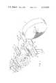
- FIG. 1is a schematic perspective view of the major components of the cup labeling apparatus in accordance with the invention.
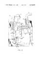
- FIG. 2is a plan view of the apparatus showing the supply of synchronized power to the major components thereof.
- FIG. 3is a side elevation view of the apparatus as seen from the left side of the view of FIG. 2.
- FIG. 4is a top plan view of the anvil roller and die roller portion of the apparatus.
- FIG. 5is a view of an end of the anvil roller taken along the lines 5--5 of FIG. 4.
- FIG. 6is an end view of the surface of the anvil roller pressure and vacuum manifold taken along the lines 6--6 of FIG. 4.
- FIG. 7is a front elevation view of the labeling drum assembly portion of the apparatus.
- FIG. 8is a cross-sectional view of the labeling drum assembly taken generally along the lines 8--8 of FIG. 7.
- FIG. 9is a partial cross-sectional view of the indexer assembly taken generally along the lines 9--9 of FIG. 1.
- FIG. 1a schematic perspective view of a preferred embodiment of cup labeling apparatus in accordance with the invention is shown generally at 20 in FIG. 1.
- Labeling stockis provided from a roll 21 carried on a core 22 and is fed over a guide roller 23, a dancer roller 24 and another guide roller 25 to a pair of intake rollers 26 and 27.
- the dancer roller 24cooperates with the guide rollers to apply proper tension to the web of coated paper stock as it is unrolled, in a manner which is common to machines utilized in the paper industry for feeding rolled paper stock.
- the paper utilized in the labeling of cups in the present inventionis preferably in the range of 1 to 2 mils thick, having a basis weight from about 9 to 20 lbs. per ream (3,000 sq. ft.).
- hot melt adhesive coatingwhich may have various formulations, typically comprising a mixture of wax and polymer.
- the hot melt adhesivemay be formed of a 30% by weight mixture of ethylene vinyl acetate, 10% by weight styrene tackifier, and about 60% by weight microcrystalline wax.
- Such a compositionis merely illustrative, since in the present invention the only requirement of the adhesive on the paper is that it be capable of melting rapidly and solidifying at moderate temperatures.
- the web of label stock 28is passed between a die roller 30 and a backup anvil roller 31.
- a raised knife-edged die (not shown in FIG. 1) on the die roller 30severs the desired label shape 32 away from the surrounding portion of the label stock as the stock web is pressed between the knife edges of the die and the surface of the anvil roller 31.
- the waste trim portion of the label stockis passed over a tensioning bar 33 and between a steel trim roller 34 and a rubber backup trim roller 35 downwardly to a discard receiving bin (not shown).
- the severed labels 32are retained on the surface of the anvil roller 31 by vacuum suction applied to small ports therein (not shown in FIG. 1) and are thereafter delivered, as the anvil roller rotates, to the surface of a synchronously rotating vacuum drum 36.
- the drum 36has a smoothly polished surface 37 with many small ports positioned to align with the labels that are laid upon the surface. As the drum 36 rotates about a central shaft 38, a portion of which is shown in FIG. 1, the labels, held on the drum surface by vacuum applied to the ports in the surface, are heated to activate the hot melt adhesive on the outward facing side of each label.
- the heating of the labelscan be accomplished in various ways; one way, as described below, is to utilize electrical resistence heaters mounted within the drum just beneath the surface of the drum, although it is apparent that radiant and convection heaters can also be used. Vacuum draw is supplied to the ports in the drum by conduits 39 extending from an air and vacuum supply manifold 40 mounted adjacent to the drum.
- Standard label stack feeding apparatusis not well adapted to handling such labels, because the labels tend to stick to one another when one is picked from the stack, and the lack of rigidity in the labels allows them to fold and jam during handling.
- Stack feedingmay be utilized to feed labels to the drum 36 where thicker labels having low adhesion between the labels in the stack are provided.
- the vacuum drum 36could be used directly as the anvil for the die roller, eliminating the anvil roller 31, with the cut labels remaining on the drum surface as they are severed from the web.
- the provision of the anvil roller 31is preferred because the surface in contact with the die edges tends to wear and the small anvil roller can be more economically replaced than the vacuum drum.
- Rotation of the drum surfacebrings each label sequentially into a position where it can contact a formed plastic cup held by one of the mandrels 41 carried on a rotating indexer plate 42.
- Clockwise rotation of the indexer plate 42 about a central shaft 43 to which it is mountedbrings a respective one of the mandrels 41, carrying a formed cup thereon, into a labeling position in which the surface of the cup is in light contact with the moving heating surface 37 of the drum 36, with each mandrel dwelling in this position until transfer of the label to the cup is completed.
- Each of the mandrels 41is mounted to rotate about its axis of symmetry and is driven, when it reaches the labeling position adjacent the drum, so as to rotate at a tangential speed which is higher than the tangential speed at which the drum is moving.
- Drawing of the label off the drum in the above described mannercauses an annulus shaped label to be pulled in its track onto the cup surface so that the line of contact between the label and the cup is always along a radial line between the two curved edges of the label.
- the cut labels 32are disposed on the surface of the drum such that the leading edge of the label will intersect the line perpendicular to the direction of drum rotation at which the cup itself contacts the drum; whereas the trailing edge of the label extends away from the position at which the cup contacts the drum.
- the cupphysically draws the label across the surface of the drum--to which the label is only weakly held by the force of vacuum, which is preferably shut off at the point of contact of the label to the cup.
- the manifold 40can be constructed, as described below, to shut off the vacuum to the ports on the drum surface in the vicinity of the area where the cup surface contacts the drum to facilitate the release of the label from the surface.
- air under pressuremay also be provided to the manifold to blow air out through the ports at the portion of the drum surface facing downwardly to blow off any labels which did not transfer properly to the cups and which remain on the drum surface.
- the roll of label stock 21may be mounted on a carriage (not shown), along with the guide rollers 23 and 25 and the dancer roller 24, to allow the position of the web of label stock to be laterally adjusted so that the die on the die roller 30 cuts the label stock at the proper position. This positioning can be important if the label is decorated, since the entire decoration should be properly centered on the cut label.
- carriage mechanismsare well known in the paper handling art, and are commonly used in printing machines.
- FIG. 2is a plan view of the apparatus of the invention which illustrates the supply of synchronized power to its components.
- the various bearings and supports required to carry drive shafts and the likeare not shown in FIG. 2 for purposes of clarity in illustration.
- the web of paper 28passes into the intake rollers 26 and 27 and is cut into the labels 32 which are delivered to the heating surface 37 of the vacuum drum 36.
- the lateral position of the web 28is sensed by an air operated position sensor 45 which adjusts the lateral position of the carriage holding the label stock roll in a manner well known in the art.
- the formed cups to be labeledmay be delivered to the mandrels 41 by any convenient means, and a stack of such cups 46 is shown being fed to a mandrel in an intake position in FIG. 2.
- a completely labeled cupis ejected from the mandrel on which it rests at a release position by a burst of air under pressure which drives the cup into a tube 47, supplied with air flow from a branch 48, which delivers the cup to the location where the cups are stacked for delivery.
- Power to drive the various components in a synchronized manneris provided from an electric motor 49 through a belt 50 to a timing pulley 51 which turns a main drive shaft 52. Power is taken off the main drive shaft through a right angle gear box 53; a universal drive shaft 54, having universal joints 55 and 56 at its respective ends; and a 10 to 1 speed reducer 57, which directs the power at right angles to an indexing cam unit 58.
- the cam mechanism 58drives the main shaft 43 of the indexer assembly on which the indexer plate 42 is mounted, and is a commercially available mechanism which provides a sequential 1/6 arc rotation followed by a selected dwell time during which one of the mandrels 41 is adjacent the drum surface 36 for pick-up of a label therefrom.
- Each mandrel 41is mounted for rotation on a mandrel shaft 60 which is journaled to the plate 42, and a beveled friction wheel 61 is mounted on the end of each shaft 60 opposite the mandrel.
- the wheel 61comes into frictional contact with a drive wheel 63 which is powered to drive the friction wheel 61 at a speed such that the tangential surface speed of a cup held by the mandrel is substantially faster than the tangential speed of the surface 36 of the vacuum drum. For example, a cup surface speed three and one half that of the drum surface has provided satisfactory results.
- the drive wheel 63is mounted on a mandrel drive shaft 64, which is driven through a right angle gear box 65 to a jack shaft 66, which itself has a timing pulley 67 mounted for rotation therewith.
- a belt 68connects the pulley 67 to a timing pulley 69 which is mounted for rotation with the main drive shaft 52.
- Poweris also taken off of the jack shaft 66 through a stub end timing pulley 70, a belt 71, a second timing pulley 72, and a right angle speed reducer 73 to the vacuum drum shaft 38.
- a slip ring power coupling 75is mounted to the end of the shaft 38 to provide an electrical connection between an outside power source and internal wires within the rotating drum 36.
- Timing pulley 77is mounted to the end of the drive shaft 52 and is connected by a belt 78 to another timing pulley 79 which drives a speed reducer 80.
- the power output of the speed reduceris provided on a shaft 81 to a pulley 82 connected by a belt 83 to a pulley 84, which is itself connected for rotation with a roller drive shaft 85.
- a timing pulley 86is mounted for rotation with the drive shaft 85 and drives, through a belt 87, the trim rollers 34 and 35 (not shown in FIG. 2).
- the power from the shaft 85is also delivered to the die and anvil rollers 30 and 31 (not shown in FIG. 2).
- a shaft 89extends from the anvil roller to a shaft position sensing unit 90 which determines the angular position of the shaft for purposes described in further detail below.
- the mounting shafts 92 and 93 of the intake rollers 26 and 27are connected together by spur gears 94 and 95 mounted to the end of the shafts 92 and 93, respectively.
- the shaft 93is shown cut in FIG. 2, since power is preferably delivered to the shaft through a variable gear reducing mechanism, as described below, which allows adjustment of the input feed rate of the web 28 into the nip formed between the die and anvil rollers.
- the feeding of the labeling stock web to the anvil and die rollersis best shown with reference to the side elevation view of FIG. 3.
- the paperis passed through the air pressure edge sensor 45, under the intake roller 26 and over the roller 27, and then downwardly into the nip formed between the die roller 30 and the anvil roller 31.
- the waste trim left after the labels have been cutis passed over the tensioning roller 33 and down between the trim rollers 34 and 35 to a waste receptacle.
- the anvil roller 31is directly coupled to the shaft 85 and is driven therewith, while the die roller 30 is driven by a spur gear 99 which is engaged with another spur gear (not shown) mounted to the shaft 85.
- the trim rollers 34 and 35are driven off of the belt 87, through a pulley 100 mounted on a shaft 101 which is directly connected to drive the trim roller 34 (not shown in FIG. 3).
- the trim roller 35is driven by a spur gear 102 engaged with another spur gear (not shown) which is mounted on the shaft 101. It is thus seen that the trim rollers 34 and 35 will always be rotated in synchrony with the die and anvil rollers.
- the shaft 93 that turns the intake rollers 26 and 27is driven by a differential transmission 105, available commercially, which is provided with power from the connecting shaft 81.
- the differential transmission 105adjusts the speed of rotation of the rollers 26 and 27 to advance or retard the incoming web of printed paper to place the printing in the proper position for subsequent cutting by the die on the die roller.
- the position of the printed materialis sensed by a photoelectric eye sensor 106 which detects the passage of a marking on the incoming paper web.
- the position of the decoration on the paperis then compared with the angular position of the anvil roller, as determined by the shaft position sensing unit 90, and a correction is applied to the differential transmission 105 by either a first reversible D.C.
- motor 108for fine corrections
- a second reversible D.C. motor 109for course corrections.
- These motorsare connected to adjust the differential within the transmission 105 through connecting chains 110 and 111, respectively.
- Such position adjustment and detection units, and the control components utilized with them,are commercially available and familiar to those skilled in the art.
- the die roller 30has a raised cutting edge 112 defining a cutting pattern.
- the cutting edge 112may be formed by machining of the parent roll stock to leave the cutting edge pattern above the remainder of the die roller surface, hardening the roller, and sharpening the cutting pattern to a knife edge.
- Raised bearing surfaces 118are left on either end of the die roller and are maintained in rolling contact with the surface of the anvil roller.
- the cutting edges 112lie just below the level of the bearing surfaces 118 such that the edges are not in hard contact with the anvil roller surface.
- the edges of the die 112would, if laid flat, define the outer periphery of the annulus sector in which the labels are to be cut.
- the hard surfaced anvil rollerhas a pattern of small surface ports 113 distributed in position to underlie a label cut by the die edges at locations inwardly adjacent the edges of such a label.
- An additional line of surface ports in the anvil rollerextends along the length of the pattern in approximately the middle of a label cut by the die 112.
- These portscommunicate with a series of cavities 114 bored longitudinally through the body of the anvil roller, shown in FIG. 5, which are normally supplied with vacuum draw.
- the outline of the shape described by the outer ports 113is essentially that of an annulus sector wrapped about the cylindrical surface of the anvil roller.
- the label carried on the anvil rolleris brought into proximity with the surface 37 of the vacuum drum 36, it is desirable that the label readily release from the anvil roller surface and be drawn onto the drum surface.
- the vacuum draw supplied to the ports 113is cut off at a position adjacent the vacuum drum, and, to provide a positive displacement of the label away from the anvil roller, air pressure may be supplied to the ports.
- the control of the vacuum and air supplied to the anvilis accomplished through a manifold 115 supplied with vacuum draw through a conduit 116 and with air under pressure through a conduit 117. As shown in the end view of the manifold 115 in FIG.
- the vacuum conduit 116terminates in communication with a vacuum groove 119 formed in the flat inner radial face of the manifold which extends over a semicircular arc.
- the flat faces 120 of the inner surface of the manifoldabut the flat radial surface of the end of the anvil roller 31 and place the groove 119 in communication with the bores 114 through most of the rotation of the anvil roller.
- the surface 120 of the manifoldcuts off the supply of vacuum to those bores 114 which are coming into proximity with the vacuum drum surface; and, ultimately, one of the bores 114 comes into communication with a recess 121 in the surface of the manifold which is connected to the air pressure conduit 117, thus delivering air under pressure to the ports 113 on the surface of the roller which extend into this particular bore 114.
- the vacuum drum assemblyis composed of an outer cylindrical drum 130, whose outer polished surface 37 carries the cut labels, and an inner cylindrical drum 131 of smaller diameter spaced away from the outer drum, with the chamber defined between the two drums being divided by seals 132 to define several air flow cavities 134.
- the front faces of the outer and inner drumare covered, and the cavities 134 sealed off from the atmosphere, by a front face plate 135.
- the drum shaft 38, carrying the drum assemblyis journaled to a pillow block 137 which rests upon a slide plate 138.
- Adjustment screws 139are threaded through elbows at either end of the slide plate 138 and into contact with the base of the pillow block 137 to allow lateral adjustment of the position of the drum to a high degree of accuracy; adjustment of the screws 139 allows the drum to be accurately placed adjacent to the surfaces of the anvil roller and a cup held by a mandrel 41.
- the position of the drumis measured by a plunger type rotary gauge 140 in contact with a plate 141 attached to the pillow block 137.
- the plate 138is itself mounted rigidly to a front support frame 142 which rests on the machine frame.
- the drum shaft 38is supported at the rear of the drum by a second pillow block 144 mounted on a rear support frame 145.
- Wires 146 carrying current from the slip ring unit 75(not shown in FIG. 8) are extended through the hollow core of the drum shaft 38 and through channels 147 to a chase 148 defined within the drum between a radial support plate 150, which carries the inner and outer drum 131 and 130, and a back cover plate 151.
- the radial plate 150is formed integrally with a spindle 153 which is keyed to rotate with the drum shaft 38.
- the wires 146extend through the chase 148 to electrical resistence heaters 155 emplaced in cavities in the outer drum 130 just beneath the surface 37 in position to heat the metal of the surface by conduction.
- the cavities 134are provided with either vacuum draw or air under pressure through the conduits 39.
- the air pressure within the cavities 134is communicated to the surface 37 of the drum through small ports 157 extending from the drum surface to the cavities.
- ports 157are spaced and disposed about the surface to underlie cut labels placed on the surface and to apply vacuum to the labels at points which are just inwardly adjacent to the outer edges of the label.
- the conduits 39are connected to a rotor portion 160 of the drum manifold 40, which is keyed to the drum shaft 38 and therefore rotates with the drum.
- the rotor 160has internal channels 161 formed therein which are directed to the radial face of the rotor; this rotor face slidingly abuts the inner radial face of a stator portion 163 of the manifold.
- the stator 163has an internal channel 164 therein which is selectively in and out of communication with the channels 161 in the rotor.
- the channel 164 in the statoris supplied with a source of vacuum draw and is formed in an arc, as shown in dashed lines in FIG. 7, which allows vacuum pressure to be supplied to the surface of the vacuum drum for most of the portion of its circumference on which labels are held.
- a second channel 165 formed in the statoris positioned to engage with the particular rotor channel 161 which is in communication with the cavity 134 which is located, at that time, past the mandrel labeling position but ahead of the position of the anvil roller.
- the stator channel 165is provided with air under pressure to thereby blow off any labels which have remained on the drum and have not transferred to cups.
- the positions of the channels 164 and 165are arranged so that the portion of the stator face between them blocks off the channels 161 in the rotor leading to the cavity 134 which is under a label which is in position to be transferred to the surface of a cup.
- Each set of ports 157 in the surface of the drum which defines the outline of a labelis formed over one of the cavities 134.
- the stator portion 163 of the drum manifoldis supported by a bracket 167 and is tightly pressed against the face of the rotor portion by the force of a compression spring 168.
- a strip 169 along the back edge of the drumis indented from the remainder of the drum surface 37.
- the indented strip 169is recessed far enough from the remainder of the surface of the drum that it does not contact a cup being labeled or particularly the raised lip typically formed on the open end of the cup.
- FIG. 9A detailed view of the indexer assembly portion of the machine 20 is shown in FIG. 9, in which portions of a mandrel, its mounting, and the indexer plate have been broken away to illustrate the internal construction of these components.
- the plate 42is rotated on a central shaft 43 which is driven by a commercially available indexing cam unit 58.
- the shafts 60 carrying the mandrels 41are journaled for rotation to the plate 41 with bearings 171 and 172.
- Internal channels 173 in the indexer platecommunicate from an opening channel 174 in the front rotary face of the indexer plate to annularly shaped channels 175 which each extend around one of the shafts 60.
- the annular channels 175communicate with channels 176 extending through the length of the shafts 60.
- the channels 176terminate in orifices 178 on the front faces of the mandrels 41.
- vacuum pressure applied to one of the mandrel shaft channels 176will pull the bottom end of a cup tightly toward the orifice 178 and thereby hold the cup tightly on the mandrel during the labeling process; and conversely, when air under pressure is applied to the channel 176, the air passing out of the orifice 178 will blow the cup off of the mandrel with considerable force.
- the annular channels 175 formed around the shafts 60, and the channels 176 within the shaftsare sealed off from the atmosphere by sealing rings 179.
- the supply of vacuum or air pressure to the channels 173 and 174is controlled by a stationary indexer manifold 181 mounted with a flat radial face abutting and sliding against the flat front radial surface of the indexer plate 42.
- a first channel 182 formed within the manifoldis connected to an exterior source of vacuum and is so arranged as to supply vacuum to the channels 174 and 173 leading to all mandrels at and between the intake and labeling positions.
- a second channel 183shown in dashed lines in FIGS.
- the manifold 181is held stationary by mounting to a manifold support adaptor 185 and is held firmly against the face of the indexer plate and in sliding contact therewith by the force of a compressed spring 186 extending between the manifold and a force plate 187 mounted to the adaptor 185.
- the adaptor 185is itself mounted to a manifold support arm 189 which is mounted to the support bar 190 for the indexer assembly.
Landscapes
- Labeling Devices (AREA)
Abstract
Description
Claims (23)
Priority Applications (4)
| Application Number | Priority Date | Filing Date | Title |
|---|---|---|---|
| US06/165,739US4332635A (en) | 1980-07-03 | 1980-07-03 | Cup labeling method and apparatus |
| CA000378796ACA1144897A (en) | 1980-07-03 | 1981-06-01 | Cup labeling method and apparatus |
| JP9645081AJPS5728731A (en) | 1980-07-03 | 1981-06-22 | Labelling method to glass and its device |
| BR8104233ABR8104233A (en) | 1980-07-03 | 1981-07-02 | APPLICATOR EQUIPMENT FOR LABELS AND CUPS LABELING PROCESS READY WITH CONE TRUNK FORMAT |
Applications Claiming Priority (1)
| Application Number | Priority Date | Filing Date | Title |
|---|---|---|---|
| US06/165,739US4332635A (en) | 1980-07-03 | 1980-07-03 | Cup labeling method and apparatus |
Publications (1)
| Publication Number | Publication Date |
|---|---|
| US4332635Atrue US4332635A (en) | 1982-06-01 |
Family
ID=22600245
Family Applications (1)
| Application Number | Title | Priority Date | Filing Date |
|---|---|---|---|
| US06/165,739Expired - LifetimeUS4332635A (en) | 1980-07-03 | 1980-07-03 | Cup labeling method and apparatus |
Country Status (4)
| Country | Link |
|---|---|
| US (1) | US4332635A (en) |
| JP (1) | JPS5728731A (en) |
| BR (1) | BR8104233A (en) |
| CA (1) | CA1144897A (en) |
Cited By (66)
| Publication number | Priority date | Publication date | Assignee | Title |
|---|---|---|---|---|
| US4455182A (en)* | 1983-09-16 | 1984-06-19 | New Way Packaging Machinery, Inc. | Tapered article labelling machine modification assembly and label application method |
| US4526645A (en)* | 1978-12-05 | 1985-07-02 | Associated Packaging Equipment Corp. Ltd. | Labelling equipment |
| US4726865A (en)* | 1985-11-02 | 1988-02-23 | Yankee Concepts, Inc. | Limp label application process |
| US4732641A (en)* | 1985-07-01 | 1988-03-22 | Dennison Manufacturing Co. | Method for rotational decoration of articles |
| EP0289878A1 (en)* | 1987-05-02 | 1988-11-09 | KRONES AG Hermann Kronseder Maschinenfabrik | Method and device for cutting complex shaped labels |
| US4816105A (en)* | 1986-04-18 | 1989-03-28 | Koyo Jidoki Co., Ltd. | Method of making punched labels or the like |
| US4832783A (en)* | 1985-07-01 | 1989-05-23 | Dennison Manufacturing Company | Apparatus for rotational decoration of articles |
| US4853169A (en)* | 1987-06-22 | 1989-08-01 | Owens-Illinois Plastic Products Inc. | Method for applying labels to blow molded articles |
| EP0501105A1 (en)* | 1991-02-28 | 1992-09-02 | Zweckform Etikettiertechnik Gesellschaft Mit Beschränkter Haftung | Device for applying labels on conical surfaces of objects, particularly of plastic cups |
| WO1996015943A3 (en)* | 1994-11-21 | 1996-08-15 | Cms Gilbreth Packaging Systems | Method and apparatus for wrapping cylindrical articles with hot melt adhesive backed label |
| US5567261A (en)* | 1992-08-06 | 1996-10-22 | Leonhard Kurz Gmbh & Co. | Method and apparatus for decorating articles having a conical peripheral surface portion |
| EP0806365A1 (en)* | 1996-05-09 | 1997-11-12 | KRONES AG Hermann Kronseder Maschinenfabrik | Labelling machine for open containers, particularly cups |
| US5709770A (en)* | 1992-08-31 | 1998-01-20 | Avery Dennison Corporation | Apparatus for decorating articles via heat transfer labelling |
| US5749990A (en)* | 1994-11-21 | 1998-05-12 | Cms Gillbreth Packaging Systems, Inc. | Method and apparatus for applying labels to articles using bottom feed conveying unit |
| US5792536A (en)* | 1996-04-30 | 1998-08-11 | Ccl Label, Inc. | Multiple-layer label |
| EP0895937A1 (en) | 1997-08-04 | 1999-02-10 | KRONES AG Hermann Kronseder Maschinenfabrik | Device for applying labels to conical surfaces of articles |
| DE19841907C1 (en)* | 1998-09-11 | 2000-03-30 | Udo Siedlaczek | Method of labelling plant pots involves feeding pots to labelling machine and restacking them |
| US6045616A (en)* | 1997-02-25 | 2000-04-04 | Gerro Plast Gmbh | Adhesive station and labeling machine |
| DE19849563A1 (en)* | 1998-10-27 | 2000-05-04 | Steinbeis Ppl Gmbh | Plastics tub labelling assembly has inverted drop to capture probe obviating synchronization between two moving parts |
| US6095218A (en)* | 1997-07-16 | 2000-08-01 | New Jersey Machine, Inc. | Transfer system for transporting articles cut from a blank of material |
| US6167935B1 (en) | 1998-09-14 | 2001-01-02 | James E. Heider | Labeling machine |
| WO2001017858A1 (en)* | 1999-09-08 | 2001-03-15 | B & H Manufacturing Company, Inc. | Lightweight vacuum drum |
| US6235345B1 (en) | 1997-02-25 | 2001-05-22 | Gerro Plast Gmbh | Label adhesive application assembly |
| US6264784B1 (en)* | 1991-09-27 | 2001-07-24 | Johnson & Johnson Inc. | Absorbent article with attached tabs and method and apparatus for making same |
| US20020050324A1 (en)* | 2000-11-01 | 2002-05-02 | Middelstadt Scott K. | Web material advance system for web material applicator |
| US6412535B1 (en)* | 2000-03-10 | 2002-07-02 | Barvit Industrial, Llc | Label application unit |
| US20020145230A1 (en)* | 2001-04-10 | 2002-10-10 | Hsien-Tsung Yeh | Injection encapsulating process for a 3D animation cup |
| US6471802B1 (en) | 1998-12-07 | 2002-10-29 | Gerro Plast Gmbh | Labeling apparatus and method |
| US20030015105A1 (en)* | 2001-07-19 | 2003-01-23 | Dewig Joseph M. | Container-labeling and -printing synchronization apparatus and process |
| US20030091779A1 (en)* | 2001-11-13 | 2003-05-15 | Brewster Frederick H. | Cutting edge for dispenser cartons |
| US20040074607A1 (en)* | 2002-10-11 | 2004-04-22 | Lintec Corporation | Laminating apparatus |
| US20040112517A1 (en)* | 2002-12-17 | 2004-06-17 | Adalis Corporation | Web material application methods and systems |
| US6811648B1 (en) | 2002-01-11 | 2004-11-02 | Polytype America Corporation | Method and machine for substantially simultaneously printing containers and applying labels thereto |
| US20050189361A1 (en)* | 2004-02-17 | 2005-09-01 | Wincup Holdings, Inc. | Beverage cup for placement in holder |
| US20050227029A1 (en)* | 2004-04-08 | 2005-10-13 | Dart Container Corporation | Paper wrapped foam cup and method of assembly |
| US20060000555A1 (en)* | 2004-06-30 | 2006-01-05 | David Schiebout | Island placement technology |
| US20060005917A1 (en)* | 2003-10-03 | 2006-01-12 | Grupo Convermex, S.A. De C.V. | Method and apparatus for producing labeled, plastic foam containers, and product of same |
| US7005028B2 (en) | 2000-11-01 | 2006-02-28 | Adalis Corporation | Web material advance system for web material applicator |
| US20060131316A1 (en)* | 2004-12-17 | 2006-06-22 | Lewis Bresler | Paper-wrapped polystyrene foam beverage container |
| US20060131317A1 (en)* | 2004-12-17 | 2006-06-22 | Lewis Bresler | Paper-wrapped polymer beverage container |
| US20060267232A1 (en)* | 2005-05-26 | 2006-11-30 | Williams Michael T | Process control system and a mold assembly for expandable plastic containers |
| US20080066853A1 (en)* | 2004-06-30 | 2008-03-20 | David Schiebout | Island placement technology |
| DE102007016426A1 (en)* | 2007-04-05 | 2008-10-09 | Cpc Haferkamp Gmbh & Co. Kg | Article e.g. bottle, labeling method, involves producing chads or punching wastes, and cutting and discharging chads or punching wastes in roller gap through and in form of individual separate cuts from roller gap, respectively |
| WO2007133864A3 (en)* | 2006-04-05 | 2009-03-26 | Jerry Schuler | Labeling apparatus for applying film labels |
| US7536767B2 (en) | 2005-05-27 | 2009-05-26 | Prairie Packaging, Inc. | Method of manufacturing a reinforced plastic foam cup |
| US7552841B2 (en) | 2005-05-27 | 2009-06-30 | Prairie Packaging, Inc. | Reinforced plastic foam cup, method of and apparatus for manufacturing same |
| US20090170679A1 (en)* | 2005-06-30 | 2009-07-02 | Hartjes Timothy P | Method of making a container employing inner liner and vents for thermal insulation |
| US20100044424A1 (en)* | 2001-07-20 | 2010-02-25 | Dixie Consumer Products Llc | Liquid container with uninterrupted comfort band and method of forming same |
| US7694843B2 (en) | 2005-05-27 | 2010-04-13 | Prairie Packaging, Inc. | Reinforced plastic foam cup, method of and apparatus for manufacturing same |
| US7704347B2 (en) | 2005-05-27 | 2010-04-27 | Prairie Packaging, Inc. | Reinforced plastic foam cup, method of and apparatus for manufacturing same |
| US7814647B2 (en) | 2005-05-27 | 2010-10-19 | Prairie Packaging, Inc. | Reinforced plastic foam cup, method of and apparatus for manufacturing same |
| US7818866B2 (en) | 2005-05-27 | 2010-10-26 | Prairie Packaging, Inc. | Method of reinforcing a plastic foam cup |
| US7938313B1 (en) | 2001-07-20 | 2011-05-10 | Dixie Consumer Products Llc | Disposable thermally insulated cup and blank therefor |
| US20110120642A1 (en)* | 2009-05-13 | 2011-05-26 | Gavin John Broad | Label Applicator Having a Vacuum Box |
| US20120301648A1 (en)* | 2009-11-24 | 2012-11-29 | Safeps Pty Ltd. | Biodegradable Expanded Polystyrene Foam And Method For Its Production |
| WO2013041272A1 (en)* | 2011-09-20 | 2013-03-28 | Robert Bosch Gmbh | Labeling device for a thermoforming system and method |
| CN103395526A (en)* | 2013-07-11 | 2013-11-20 | 杭州中亚机械股份有限公司 | Label cutting and voluming mechanism |
| US8622232B2 (en) | 2005-06-30 | 2014-01-07 | Dixie Consumer Products Llc | Method of making a container employing inner liner and vents for thermal insulation |
| US8828170B2 (en) | 2010-03-04 | 2014-09-09 | Pactiv LLC | Apparatus and method for manufacturing reinforced containers |
| US9168714B2 (en) | 2005-06-30 | 2015-10-27 | Dixie Consumer Products Llc | Methods for making paperboard blanks and paperboard products therefrom |
| US9555914B2 (en) | 2009-05-13 | 2017-01-31 | The Procter & Gamble Company | Label applicator having a heat idler |
| US9731489B2 (en) | 2013-05-29 | 2017-08-15 | H.B. Fuller Company | Material application system |
| US9926098B2 (en) | 2012-06-25 | 2018-03-27 | Gpcp Ip Holdings Llc | Paperboard blanks having a shrinkable film adhered thereto and paperboard container made therefrom |
| US11161332B2 (en) | 2018-03-05 | 2021-11-02 | H.B. Fuller Company | Web material application systems and methods |
| PL441516A1 (en)* | 2022-06-21 | 2023-12-27 | Sergei Maltcev | Apparatus for sticking self-adhesive labels to containers, method of sticking same to containers |
| FR3142750A1 (en)* | 2022-10-31 | 2024-06-07 | Machines Pages | Process for applying a label to molded packaging with a frustoconical shape, tools allowing the implementation of said process. |
Families Citing this family (3)
| Publication number | Priority date | Publication date | Assignee | Title |
|---|---|---|---|---|
| CN109107912B (en)* | 2018-09-19 | 2023-12-15 | 浙江福川家居用品有限公司 | Medical stainless steel cup body quality detection and labeling automatic assembly system |
| CN109606884B (en)* | 2018-12-10 | 2021-01-26 | 温州大学瓯江学院 | A labeling machine with cutting function |
| CN115308228B (en)* | 2022-08-05 | 2023-04-25 | 深圳市俱进纸品包装有限公司 | Visual inspection device for printed label production system |
Citations (8)
| Publication number | Priority date | Publication date | Assignee | Title |
|---|---|---|---|---|
| US2791317A (en)* | 1955-11-14 | 1957-05-07 | Upjohn Co | Device for indexing and rotating articles |
| US3562050A (en)* | 1967-10-23 | 1971-02-09 | American Can Co | Method of applying a strip member to a cylindrical container body |
| US3565724A (en)* | 1967-07-31 | 1971-02-23 | Nishimura Seisakusho Co | Automatic labelling machine |
| US3598675A (en)* | 1966-11-21 | 1971-08-10 | American Can Co | Method for securing strip members to container bodies |
| US3676271A (en)* | 1967-10-23 | 1972-07-11 | American Can Co | Apparatus for applying a strip member to a cylindrical container body |
| US3690997A (en)* | 1966-11-21 | 1972-09-12 | American Can Co | Apparatus for securing strip members to container bodies |
| US4181555A (en)* | 1978-02-07 | 1980-01-01 | B & H Manufacturing Company, Inc. | Labeling apparatus and method for continuously severing labels from continuous label stock and applying the severed labels to containers |
| US4210481A (en)* | 1978-11-14 | 1980-07-01 | Njm, Inc. | Labeling machines |
- 1980
- 1980-07-03USUS06/165,739patent/US4332635A/ennot_activeExpired - Lifetime
- 1981
- 1981-06-01CACA000378796Apatent/CA1144897A/ennot_activeExpired
- 1981-06-22JPJP9645081Apatent/JPS5728731A/enactivePending
- 1981-07-02BRBR8104233Apatent/BR8104233A/enunknown
Patent Citations (9)
| Publication number | Priority date | Publication date | Assignee | Title |
|---|---|---|---|---|
| US2791317A (en)* | 1955-11-14 | 1957-05-07 | Upjohn Co | Device for indexing and rotating articles |
| US3598675A (en)* | 1966-11-21 | 1971-08-10 | American Can Co | Method for securing strip members to container bodies |
| US3690997A (en)* | 1966-11-21 | 1972-09-12 | American Can Co | Apparatus for securing strip members to container bodies |
| US3598675B1 (en)* | 1966-11-21 | 1990-01-09 | American National Can Co | |
| US3565724A (en)* | 1967-07-31 | 1971-02-23 | Nishimura Seisakusho Co | Automatic labelling machine |
| US3562050A (en)* | 1967-10-23 | 1971-02-09 | American Can Co | Method of applying a strip member to a cylindrical container body |
| US3676271A (en)* | 1967-10-23 | 1972-07-11 | American Can Co | Apparatus for applying a strip member to a cylindrical container body |
| US4181555A (en)* | 1978-02-07 | 1980-01-01 | B & H Manufacturing Company, Inc. | Labeling apparatus and method for continuously severing labels from continuous label stock and applying the severed labels to containers |
| US4210481A (en)* | 1978-11-14 | 1980-07-01 | Njm, Inc. | Labeling machines |
Non-Patent Citations (3)
| Title |
|---|
| NJM, Inc. Brochure, "Thorobred Pony 350".* |
| NJM, Inc. product description pp. 10,932S; 10,933S; and 10,935S.* |
| Packaging Engineering, Jun. 1980, p. 44, "The Thorobred Tames a Tricky Container".* |
Cited By (104)
| Publication number | Priority date | Publication date | Assignee | Title |
|---|---|---|---|---|
| US4526645A (en)* | 1978-12-05 | 1985-07-02 | Associated Packaging Equipment Corp. Ltd. | Labelling equipment |
| US4455182A (en)* | 1983-09-16 | 1984-06-19 | New Way Packaging Machinery, Inc. | Tapered article labelling machine modification assembly and label application method |
| US4732641A (en)* | 1985-07-01 | 1988-03-22 | Dennison Manufacturing Co. | Method for rotational decoration of articles |
| US4832783A (en)* | 1985-07-01 | 1989-05-23 | Dennison Manufacturing Company | Apparatus for rotational decoration of articles |
| US4726865A (en)* | 1985-11-02 | 1988-02-23 | Yankee Concepts, Inc. | Limp label application process |
| US4816105A (en)* | 1986-04-18 | 1989-03-28 | Koyo Jidoki Co., Ltd. | Method of making punched labels or the like |
| EP0289878A1 (en)* | 1987-05-02 | 1988-11-09 | KRONES AG Hermann Kronseder Maschinenfabrik | Method and device for cutting complex shaped labels |
| US4880369A (en)* | 1987-06-22 | 1989-11-14 | Owens-Illinois Plastic Products Inc. | Apparatus for applying labels to blow molded articles |
| US4853169A (en)* | 1987-06-22 | 1989-08-01 | Owens-Illinois Plastic Products Inc. | Method for applying labels to blow molded articles |
| EP0501105A1 (en)* | 1991-02-28 | 1992-09-02 | Zweckform Etikettiertechnik Gesellschaft Mit Beschränkter Haftung | Device for applying labels on conical surfaces of objects, particularly of plastic cups |
| US6264784B1 (en)* | 1991-09-27 | 2001-07-24 | Johnson & Johnson Inc. | Absorbent article with attached tabs and method and apparatus for making same |
| US5567261A (en)* | 1992-08-06 | 1996-10-22 | Leonhard Kurz Gmbh & Co. | Method and apparatus for decorating articles having a conical peripheral surface portion |
| US5709770A (en)* | 1992-08-31 | 1998-01-20 | Avery Dennison Corporation | Apparatus for decorating articles via heat transfer labelling |
| WO1996015943A3 (en)* | 1994-11-21 | 1996-08-15 | Cms Gilbreth Packaging Systems | Method and apparatus for wrapping cylindrical articles with hot melt adhesive backed label |
| US5749990A (en)* | 1994-11-21 | 1998-05-12 | Cms Gillbreth Packaging Systems, Inc. | Method and apparatus for applying labels to articles using bottom feed conveying unit |
| US5779835A (en)* | 1994-11-21 | 1998-07-14 | Cms Gilbreth Packaging Systems, Inc. | Method and apparatus for applying labels to articles using bottom feed chain conveyor |
| US5792536A (en)* | 1996-04-30 | 1998-08-11 | Ccl Label, Inc. | Multiple-layer label |
| EP0806365A1 (en)* | 1996-05-09 | 1997-11-12 | KRONES AG Hermann Kronseder Maschinenfabrik | Labelling machine for open containers, particularly cups |
| US6235345B1 (en) | 1997-02-25 | 2001-05-22 | Gerro Plast Gmbh | Label adhesive application assembly |
| US6045616A (en)* | 1997-02-25 | 2000-04-04 | Gerro Plast Gmbh | Adhesive station and labeling machine |
| US6095218A (en)* | 1997-07-16 | 2000-08-01 | New Jersey Machine, Inc. | Transfer system for transporting articles cut from a blank of material |
| EP0895937A1 (en) | 1997-08-04 | 1999-02-10 | KRONES AG Hermann Kronseder Maschinenfabrik | Device for applying labels to conical surfaces of articles |
| DE19841907C2 (en)* | 1998-09-11 | 2003-06-26 | Udo Siedlaczek | Method and device for labeling flower pots |
| DE19841907C1 (en)* | 1998-09-11 | 2000-03-30 | Udo Siedlaczek | Method of labelling plant pots involves feeding pots to labelling machine and restacking them |
| US6167935B1 (en) | 1998-09-14 | 2001-01-02 | James E. Heider | Labeling machine |
| DE19849563A1 (en)* | 1998-10-27 | 2000-05-04 | Steinbeis Ppl Gmbh | Plastics tub labelling assembly has inverted drop to capture probe obviating synchronization between two moving parts |
| US6471802B1 (en) | 1998-12-07 | 2002-10-29 | Gerro Plast Gmbh | Labeling apparatus and method |
| WO2001017858A1 (en)* | 1999-09-08 | 2001-03-15 | B & H Manufacturing Company, Inc. | Lightweight vacuum drum |
| US6412535B1 (en)* | 2000-03-10 | 2002-07-02 | Barvit Industrial, Llc | Label application unit |
| US6913662B2 (en)* | 2000-03-10 | 2005-07-05 | Barvit Industrial, Llc | Label application method |
| US20020166634A1 (en)* | 2000-03-10 | 2002-11-14 | Barvit Industrial, Llc | Label application method |
| US20020050324A1 (en)* | 2000-11-01 | 2002-05-02 | Middelstadt Scott K. | Web material advance system for web material applicator |
| US7005028B2 (en) | 2000-11-01 | 2006-02-28 | Adalis Corporation | Web material advance system for web material applicator |
| US20040094263A1 (en)* | 2000-11-01 | 2004-05-20 | Middelstadt Scott K | Web material advance system for web material applicator |
| US7135083B2 (en) | 2000-11-01 | 2006-11-14 | Adalis Corporation | Web material advance system for web material applicator |
| US6858105B2 (en) | 2000-11-01 | 2005-02-22 | Adalis Corporation | Splicing system affording a continuous web material supply for an applicator |
| US6860309B2 (en) | 2000-11-01 | 2005-03-01 | Adalis Corporation | Splicing system affording a continuous web material supply for an applicator |
| US6893528B2 (en) | 2000-11-01 | 2005-05-17 | Adalis Corporation | Web material advance system for web material applicator |
| US20020145230A1 (en)* | 2001-04-10 | 2002-10-10 | Hsien-Tsung Yeh | Injection encapsulating process for a 3D animation cup |
| US20030015105A1 (en)* | 2001-07-19 | 2003-01-23 | Dewig Joseph M. | Container-labeling and -printing synchronization apparatus and process |
| US7011728B2 (en)* | 2001-07-19 | 2006-03-14 | Berry Plastics Corporation | Container-labeling and-printing synchronization apparatus and process |
| US7938313B1 (en) | 2001-07-20 | 2011-05-10 | Dixie Consumer Products Llc | Disposable thermally insulated cup and blank therefor |
| US7913873B2 (en)* | 2001-07-20 | 2011-03-29 | Dixie Consumer Products Llc | Liquid container with uninterrupted comfort band and method of forming same |
| US20100044424A1 (en)* | 2001-07-20 | 2010-02-25 | Dixie Consumer Products Llc | Liquid container with uninterrupted comfort band and method of forming same |
| US20030091779A1 (en)* | 2001-11-13 | 2003-05-15 | Brewster Frederick H. | Cutting edge for dispenser cartons |
| USRE40719E1 (en)* | 2002-01-11 | 2009-06-09 | Polytype America Corporation | Method and machine for substantially simultaneously printing containers and applying labels thereto |
| US6811648B1 (en) | 2002-01-11 | 2004-11-02 | Polytype America Corporation | Method and machine for substantially simultaneously printing containers and applying labels thereto |
| US20040074607A1 (en)* | 2002-10-11 | 2004-04-22 | Lintec Corporation | Laminating apparatus |
| US7172666B2 (en) | 2002-12-17 | 2007-02-06 | Groves Matthew E | Web material application methods and systems |
| US20040112517A1 (en)* | 2002-12-17 | 2004-06-17 | Adalis Corporation | Web material application methods and systems |
| US20110011523A1 (en)* | 2003-10-03 | 2011-01-20 | Grupo Convermex, S.A. De C.V. | Method and apparatus for producing labeled, plastic foam containers, and product of same |
| US9321557B2 (en) | 2003-10-03 | 2016-04-26 | Grupo Convermex, S.A. De C.V. | Method and apparatus for producing labeled, plastic foam containers, and product of same |
| US20060005917A1 (en)* | 2003-10-03 | 2006-01-12 | Grupo Convermex, S.A. De C.V. | Method and apparatus for producing labeled, plastic foam containers, and product of same |
| US8617681B2 (en) | 2003-10-03 | 2013-12-31 | Grupo Convermex, S.A. De C.V. | Method and apparatus for producing labeled, plastic foam containers, and product of same |
| US8105459B2 (en) | 2003-10-03 | 2012-01-31 | Grupo Convermex, S.A. De C.V. | Method and apparatus for producing labeled, plastic foam containers, and product of same |
| US20050189361A1 (en)* | 2004-02-17 | 2005-09-01 | Wincup Holdings, Inc. | Beverage cup for placement in holder |
| US7856793B2 (en) | 2004-04-08 | 2010-12-28 | Dart Container Corporation | Apparatus for assembling a wrapper to a cup |
| US20090229221A1 (en)* | 2004-04-08 | 2009-09-17 | Dart Container Corporation | Apparatus for Assembling a Wrapper to a Cup |
| EP1892189A3 (en)* | 2004-04-08 | 2008-06-11 | Dart Container Corporation | Wrapping apparatus for foam cups |
| US9527620B2 (en) | 2004-04-08 | 2016-12-27 | Dart Container Corporation | Paper wrapped foam cup and method of assembly |
| EP1892189A2 (en) | 2004-04-08 | 2008-02-27 | Dart Container Corporation | Wrapping apparatus for foam cups |
| AU2005233138B2 (en)* | 2004-04-08 | 2010-09-30 | Dart Container Corporation | Paper wrapped foam cup and method of assembly |
| WO2005100167A1 (en)* | 2004-04-08 | 2005-10-27 | Dart Container Corporation | Paper wrapped foam cup and method of assembly |
| US7549273B2 (en) | 2004-04-08 | 2009-06-23 | Dart Container Corporation | Paper wrapped foam cup and method of assembly |
| US20080098698A1 (en)* | 2004-04-08 | 2008-05-01 | Dart Container Corporation | Paper Wrapped Foam Cup and Method of Assembly |
| US20050227029A1 (en)* | 2004-04-08 | 2005-10-13 | Dart Container Corporation | Paper wrapped foam cup and method of assembly |
| US8097110B2 (en) | 2004-06-30 | 2012-01-17 | Delta Industrial Services, Inc. | Island placement technology |
| US7293593B2 (en) | 2004-06-30 | 2007-11-13 | Delta Industrial Services, In. | Island placement technology |
| US20060000555A1 (en)* | 2004-06-30 | 2006-01-05 | David Schiebout | Island placement technology |
| US20080066853A1 (en)* | 2004-06-30 | 2008-03-20 | David Schiebout | Island placement technology |
| US20060131316A1 (en)* | 2004-12-17 | 2006-06-22 | Lewis Bresler | Paper-wrapped polystyrene foam beverage container |
| US20060131317A1 (en)* | 2004-12-17 | 2006-06-22 | Lewis Bresler | Paper-wrapped polymer beverage container |
| US20060267232A1 (en)* | 2005-05-26 | 2006-11-30 | Williams Michael T | Process control system and a mold assembly for expandable plastic containers |
| US7918005B2 (en)* | 2005-05-27 | 2011-04-05 | Prairie Packaging, Inc. | Reinforced foam cup, method of and apparatus for manufacturing same |
| US8087147B2 (en) | 2005-05-27 | 2012-01-03 | Prairie Packaging, Inc. | Method of reinforcing a plastic foam cup |
| US8622208B2 (en) | 2005-05-27 | 2014-01-07 | Pactiv LLC | Reinforced cup |
| US7818866B2 (en) | 2005-05-27 | 2010-10-26 | Prairie Packaging, Inc. | Method of reinforcing a plastic foam cup |
| US7814647B2 (en) | 2005-05-27 | 2010-10-19 | Prairie Packaging, Inc. | Reinforced plastic foam cup, method of and apparatus for manufacturing same |
| US7918016B2 (en)* | 2005-05-27 | 2011-04-05 | Prairie Packaging, Inc. | Reinforced plastic foam cup, method of and apparatus for manufacturing same |
| US7704347B2 (en) | 2005-05-27 | 2010-04-27 | Prairie Packaging, Inc. | Reinforced plastic foam cup, method of and apparatus for manufacturing same |
| US7694843B2 (en) | 2005-05-27 | 2010-04-13 | Prairie Packaging, Inc. | Reinforced plastic foam cup, method of and apparatus for manufacturing same |
| US20100323866A1 (en)* | 2005-05-27 | 2010-12-23 | Prairie Packaging, Inc. | Reinforced plastic foam cup, method of and apparatus for manufacturing same |
| US7536767B2 (en) | 2005-05-27 | 2009-05-26 | Prairie Packaging, Inc. | Method of manufacturing a reinforced plastic foam cup |
| US7552841B2 (en) | 2005-05-27 | 2009-06-30 | Prairie Packaging, Inc. | Reinforced plastic foam cup, method of and apparatus for manufacturing same |
| US20090170679A1 (en)* | 2005-06-30 | 2009-07-02 | Hartjes Timothy P | Method of making a container employing inner liner and vents for thermal insulation |
| US9168714B2 (en) | 2005-06-30 | 2015-10-27 | Dixie Consumer Products Llc | Methods for making paperboard blanks and paperboard products therefrom |
| US8622232B2 (en) | 2005-06-30 | 2014-01-07 | Dixie Consumer Products Llc | Method of making a container employing inner liner and vents for thermal insulation |
| US7841974B2 (en) | 2005-06-30 | 2010-11-30 | Dixie Consumer Products Llc | Method of making a container employing inner liner and vents for thermal insulation |
| WO2007133864A3 (en)* | 2006-04-05 | 2009-03-26 | Jerry Schuler | Labeling apparatus for applying film labels |
| DE102007016426A1 (en)* | 2007-04-05 | 2008-10-09 | Cpc Haferkamp Gmbh & Co. Kg | Article e.g. bottle, labeling method, involves producing chads or punching wastes, and cutting and discharging chads or punching wastes in roller gap through and in form of individual separate cuts from roller gap, respectively |
| US20110120642A1 (en)* | 2009-05-13 | 2011-05-26 | Gavin John Broad | Label Applicator Having a Vacuum Box |
| US9555914B2 (en) | 2009-05-13 | 2017-01-31 | The Procter & Gamble Company | Label applicator having a heat idler |
| US20120301648A1 (en)* | 2009-11-24 | 2012-11-29 | Safeps Pty Ltd. | Biodegradable Expanded Polystyrene Foam And Method For Its Production |
| US9676141B2 (en) | 2010-03-04 | 2017-06-13 | Pactiv LLC | Apparatus and method for manufacturing reinforced containers |
| US8828170B2 (en) | 2010-03-04 | 2014-09-09 | Pactiv LLC | Apparatus and method for manufacturing reinforced containers |
| WO2013041272A1 (en)* | 2011-09-20 | 2013-03-28 | Robert Bosch Gmbh | Labeling device for a thermoforming system and method |
| US9481123B2 (en) | 2011-09-20 | 2016-11-01 | Robert Bosch Gmbh | Labeling device for a thermoforming system and method |
| US9926098B2 (en) | 2012-06-25 | 2018-03-27 | Gpcp Ip Holdings Llc | Paperboard blanks having a shrinkable film adhered thereto and paperboard container made therefrom |
| US9731489B2 (en) | 2013-05-29 | 2017-08-15 | H.B. Fuller Company | Material application system |
| CN103395526B (en)* | 2013-07-11 | 2015-11-25 | 杭州中亚机械股份有限公司 | A kind of Cai Biao label mechanism |
| CN103395526A (en)* | 2013-07-11 | 2013-11-20 | 杭州中亚机械股份有限公司 | Label cutting and voluming mechanism |
| US11161332B2 (en) | 2018-03-05 | 2021-11-02 | H.B. Fuller Company | Web material application systems and methods |
| PL441516A1 (en)* | 2022-06-21 | 2023-12-27 | Sergei Maltcev | Apparatus for sticking self-adhesive labels to containers, method of sticking same to containers |
| FR3142750A1 (en)* | 2022-10-31 | 2024-06-07 | Machines Pages | Process for applying a label to molded packaging with a frustoconical shape, tools allowing the implementation of said process. |
Also Published As
| Publication number | Publication date |
|---|---|
| JPS5728731A (en) | 1982-02-16 |
| CA1144897A (en) | 1983-04-19 |
| BR8104233A (en) | 1982-03-23 |
Similar Documents
| Publication | Publication Date | Title |
|---|---|---|
| US4332635A (en) | Cup labeling method and apparatus | |
| US4526645A (en) | Labelling equipment | |
| US4561928A (en) | Labelling machine | |
| US5458729A (en) | Apparatus and method for applying labels onto small cylindrical articles using improved film feed and cutting system | |
| US4447280A (en) | Labelling machine | |
| AU712021B2 (en) | Method of labeling containers | |
| US4076786A (en) | Method for producing container label blanks from a web | |
| CA1155806A (en) | Labelling equipment | |
| US4801348A (en) | Film supply apparatus | |
| US5344519A (en) | Apparatus for applying labels onto small cylindrical articles having improved vacuum and air pressure porting for label transport drum | |
| GB2081205A (en) | Application of labels to articles | |
| JPH06211223A (en) | Apparatus for applying a label with improved vacuum and pneumatic feed hole features to a label transport drum to small cylindrical articles | |
| JP2002531341A (en) | Label preparation apparatus and method | |
| US5480502A (en) | Method and apparatus for applying labels to articles using cooling air on label receiving positions | |
| JPH0124622B2 (en) | ||
| US4045275A (en) | Machine for applying tapes to moving product | |
| JPH0858755A (en) | Labeling machine | |
| US4021286A (en) | Apparatus for producing shrunken pilfer-proof neck labels for containers | |
| US4025381A (en) | Apparatus for producing shrunken pilfer-proof neck labels for containers | |
| WO1995027613A1 (en) | Method and apparatus for producing a sleeve label and container with such sleeve label | |
| CN113968044A (en) | A kind of manufacturing device and manufacturing method of takeaway handbag | |
| JPH0231365Y2 (en) | ||
| CA1177792A (en) | Labelling machine | |
| US4018644A (en) | Apparatus for producing shrunken pilfer-proof neck labels for containers | |
| JPS62275751A (en) | Transfer device |
Legal Events
| Date | Code | Title | Description |
|---|---|---|---|
| STCF | Information on status: patent grant | Free format text:PATENTED CASE | |
| AS | Assignment | Owner name:JAMES RIVER-DIXIE/NORTHERN, INC., A CORP. OF VA Free format text:ASSIGNMENT OF ASSIGNORS INTEREST.;ASSIGNOR:AMERICAN CAN COMPANY;REEL/FRAME:004047/0849 Effective date:19820924 Owner name:JAMES RIVER-DIXIE/NORTHERN, INC., A CORP. OF, VIRG Free format text:ASSIGNMENT OF ASSIGNORS INTEREST;ASSIGNOR:AMERICAN CAN COMPANY;REEL/FRAME:004047/0849 Effective date:19820924 | |
| AS | Assignment | Owner name:JAMES RIVER-DIXIE/NORTHERN, INC., A CORP. OF VA. Free format text:ASSIGNMENT OF ASSIGNORS INTEREST.;ASSIGNOR:AMERICAN CAN COMPANY;REEL/FRAME:004114/0605 | |
| AS | Assignment | Owner name:JAMES RIVER-NORWALK, INC., RIVERPARK, P.O. BOX 600 Free format text:ASSIGNMENT OF ASSIGNORS INTEREST.;ASSIGNOR:JAMES RIVER-DIXIE/NORTHERN, INC.;REEL/FRAME:004332/0546 Effective date:19840905 | |
| AS | Assignment | Owner name:JAMES RIVER PAPER COMPANY, INC., A CORP. OF VA. Free format text:MERGER;ASSIGNOR:JAMES RIVER-NORWALK, INC.;REEL/FRAME:005152/0359 Effective date:19890420 |