US4328592A - Heart valve prosthesis - Google Patents
Heart valve prosthesisDownload PDFInfo
- Publication number
- US4328592A US4328592AUS06/111,488US11148880AUS4328592AUS 4328592 AUS4328592 AUS 4328592AUS 11148880 AUS11148880 AUS 11148880AUS 4328592 AUS4328592 AUS 4328592A
- Authority
- US
- United States
- Prior art keywords
- leaflets
- depressions
- valve body
- guides
- heart valve
- Prior art date
- Legal status (The legal status is an assumption and is not a legal conclusion. Google has not performed a legal analysis and makes no representation as to the accuracy of the status listed.)
- Expired - Lifetime, expires
Links
- 210000003709heart valveAnatomy0.000titleclaimsabstractdescription36
- 210000004369bloodAnatomy0.000claimsabstractdescription25
- 239000008280bloodSubstances0.000claimsabstractdescription25
- 230000000295complement effectEffects0.000claimsabstractdescription3
- 230000017531blood circulationEffects0.000claimsdescription22
- 238000011144upstream manufacturingMethods0.000claimsdescription9
- 230000005484gravityEffects0.000claimsdescription5
- 230000000903blocking effectEffects0.000claims4
- 230000013011matingEffects0.000claims1
- 230000004044responseEffects0.000abstractdescription3
- 238000003754machiningMethods0.000description6
- 206010053567CoagulopathiesDiseases0.000description5
- 230000035602clottingEffects0.000description5
- 206010067171RegurgitationDiseases0.000description4
- 239000002296pyrolytic carbonSubstances0.000description4
- OKTJSMMVPCPJKN-UHFFFAOYSA-NCarbonChemical compound[C]OKTJSMMVPCPJKN-UHFFFAOYSA-N0.000description3
- 238000010276constructionMethods0.000description3
- 238000005520cutting processMethods0.000description3
- 230000000694effectsEffects0.000description3
- 229910002804graphiteInorganic materials0.000description3
- 239000010439graphiteSubstances0.000description3
- 239000000463materialSubstances0.000description3
- 230000004048modificationEffects0.000description3
- 238000012986modificationMethods0.000description3
- 230000007704transitionEffects0.000description3
- 210000000709aortaAnatomy0.000description2
- 230000008901benefitEffects0.000description2
- 238000006073displacement reactionMethods0.000description2
- 238000005086pumpingMethods0.000description2
- 230000003252repetitive effectEffects0.000description2
- 238000007789sealingMethods0.000description2
- 238000005406washingMethods0.000description2
- 206010018910HaemolysisDiseases0.000description1
- 230000009471actionEffects0.000description1
- 230000015572biosynthetic processEffects0.000description1
- 210000000601blood cellAnatomy0.000description1
- 230000023555blood coagulationEffects0.000description1
- 210000005242cardiac chamberAnatomy0.000description1
- 230000008859changeEffects0.000description1
- 239000002131composite materialSubstances0.000description1
- 230000002950deficientEffects0.000description1
- 238000007667floatingMethods0.000description1
- 238000011010flushing procedureMethods0.000description1
- 210000002837heart atriumAnatomy0.000description1
- 210000005003heart tissueAnatomy0.000description1
- 230000008588hemolysisEffects0.000description1
- 238000004519manufacturing processMethods0.000description1
- 210000004115mitral valveAnatomy0.000description1
- 230000001453nonthrombogenic effectEffects0.000description1
- 230000002093peripheral effectEffects0.000description1
- 230000009467reductionEffects0.000description1
- 238000009958sewingMethods0.000description1
- 239000000758substrateSubstances0.000description1
Images


Classifications
- A—HUMAN NECESSITIES
- A61—MEDICAL OR VETERINARY SCIENCE; HYGIENE
- A61F—FILTERS IMPLANTABLE INTO BLOOD VESSELS; PROSTHESES; DEVICES PROVIDING PATENCY TO, OR PREVENTING COLLAPSING OF, TUBULAR STRUCTURES OF THE BODY, e.g. STENTS; ORTHOPAEDIC, NURSING OR CONTRACEPTIVE DEVICES; FOMENTATION; TREATMENT OR PROTECTION OF EYES OR EARS; BANDAGES, DRESSINGS OR ABSORBENT PADS; FIRST-AID KITS
- A61F2/00—Filters implantable into blood vessels; Prostheses, i.e. artificial substitutes or replacements for parts of the body; Appliances for connecting them with the body; Devices providing patency to, or preventing collapsing of, tubular structures of the body, e.g. stents
- A61F2/02—Prostheses implantable into the body
- A61F2/24—Heart valves ; Vascular valves, e.g. venous valves; Heart implants, e.g. passive devices for improving the function of the native valve or the heart muscle; Transmyocardial revascularisation [TMR] devices; Valves implantable in the body
- A61F2/2403—Heart valves ; Vascular valves, e.g. venous valves; Heart implants, e.g. passive devices for improving the function of the native valve or the heart muscle; Transmyocardial revascularisation [TMR] devices; Valves implantable in the body with pivoting rigid closure members
- A—HUMAN NECESSITIES
- A61—MEDICAL OR VETERINARY SCIENCE; HYGIENE
- A61F—FILTERS IMPLANTABLE INTO BLOOD VESSELS; PROSTHESES; DEVICES PROVIDING PATENCY TO, OR PREVENTING COLLAPSING OF, TUBULAR STRUCTURES OF THE BODY, e.g. STENTS; ORTHOPAEDIC, NURSING OR CONTRACEPTIVE DEVICES; FOMENTATION; TREATMENT OR PROTECTION OF EYES OR EARS; BANDAGES, DRESSINGS OR ABSORBENT PADS; FIRST-AID KITS
- A61F2/00—Filters implantable into blood vessels; Prostheses, i.e. artificial substitutes or replacements for parts of the body; Appliances for connecting them with the body; Devices providing patency to, or preventing collapsing of, tubular structures of the body, e.g. stents
- A61F2/02—Prostheses implantable into the body
- A61F2/24—Heart valves ; Vascular valves, e.g. venous valves; Heart implants, e.g. passive devices for improving the function of the native valve or the heart muscle; Transmyocardial revascularisation [TMR] devices; Valves implantable in the body
- A61F2/2409—Support rings therefor, e.g. for connecting valves to tissue
- A—HUMAN NECESSITIES
- A61—MEDICAL OR VETERINARY SCIENCE; HYGIENE
- A61F—FILTERS IMPLANTABLE INTO BLOOD VESSELS; PROSTHESES; DEVICES PROVIDING PATENCY TO, OR PREVENTING COLLAPSING OF, TUBULAR STRUCTURES OF THE BODY, e.g. STENTS; ORTHOPAEDIC, NURSING OR CONTRACEPTIVE DEVICES; FOMENTATION; TREATMENT OR PROTECTION OF EYES OR EARS; BANDAGES, DRESSINGS OR ABSORBENT PADS; FIRST-AID KITS
- A61F13/00—Bandages or dressings; Absorbent pads
- A61F13/15—Absorbent pads, e.g. sanitary towels, swabs or tampons for external or internal application to the body; Supporting or fastening means therefor; Tampon applicators
- A61F13/15577—Apparatus or processes for manufacturing
- A61F2013/15821—Apparatus or processes for manufacturing characterized by the apparatus for manufacturing
- A61F2013/15845—Apparatus or processes for manufacturing characterized by the apparatus for manufacturing using a specific cam for programming the apparatus
- Y—GENERAL TAGGING OF NEW TECHNOLOGICAL DEVELOPMENTS; GENERAL TAGGING OF CROSS-SECTIONAL TECHNOLOGIES SPANNING OVER SEVERAL SECTIONS OF THE IPC; TECHNICAL SUBJECTS COVERED BY FORMER USPC CROSS-REFERENCE ART COLLECTIONS [XRACs] AND DIGESTS
- Y10—TECHNICAL SUBJECTS COVERED BY FORMER USPC
- Y10T—TECHNICAL SUBJECTS COVERED BY FORMER US CLASSIFICATION
- Y10T137/00—Fluid handling
- Y10T137/7722—Line condition change responsive valves
- Y10T137/7837—Direct response valves [i.e., check valve type]
- Y10T137/7838—Plural
- Y10T137/7839—Dividing and recombining in a single flow path
- Y—GENERAL TAGGING OF NEW TECHNOLOGICAL DEVELOPMENTS; GENERAL TAGGING OF CROSS-SECTIONAL TECHNOLOGIES SPANNING OVER SEVERAL SECTIONS OF THE IPC; TECHNICAL SUBJECTS COVERED BY FORMER USPC CROSS-REFERENCE ART COLLECTIONS [XRACs] AND DIGESTS
- Y10—TECHNICAL SUBJECTS COVERED BY FORMER USPC
- Y10T—TECHNICAL SUBJECTS COVERED BY FORMER US CLASSIFICATION
- Y10T137/00—Fluid handling
- Y10T137/7722—Line condition change responsive valves
- Y10T137/7837—Direct response valves [i.e., check valve type]
- Y10T137/7898—Pivoted valves
- Y10T137/7903—Weight biased
Definitions
- This inventionrelates to heart valve prostheses for replacement of defective natural valves and more particularly to heart valve prostheses using a pair of pivoting valve members, preferably ones which are arcuate in cross section.
- Disc-type heart valveshave also been developed which use two members or leaflets, instead of a single disc, which leaflets rotate about parallel axes as a part of the opening and closing of the valve.
- British Pat. No. 1,160,008shows an early version of such a valve
- the inventionprovides improved versions of two-leaflet heart valve prostheses having excellent blood flow characteristics.
- Guidesextend from opposite sides of each of the leaflets and are received in depressions formed in the interior wall surfaces of a pair of standards which extend downstream from an annular valve body.
- the valve membersare preferably curved in cross section, and each pivots about an eccentric axis.
- the depressionsare preferably elongated or enlarged so that the axis of pivot of each leaflet changes relative to the valve body, and this movement in the depressions prevents blood clotting from beginning in an otherwise stagnant region.
- the location of the pivot axesslightly downstream of the orifice defined by the annular valve body, essentially removes them from the region of greatest constriction and provides the valve with excellent flow characteristics.
- the heart valvesopen and close easily and reliably and exhibit excellent resistance to wear.
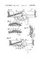
- FIG. 1is a perspective view of a heart valve embodying various features of the invention and having a pair of leaflets which are shown in the open position;
- FIG. 2is a plan view, reduced in size, of the valve of FIG. 1 shown in the open position;
- FIG. 3is an enlarged plan view showing the valve of FIG. 1 in the closed position
- FIGS. 4 and 5are enlarged sectional views taken along the line 4--4 of FIG. 3, showing the valve in the closed and open positions;
- FIG. 6is a fragmentary plan view of the valve as shown in FIG. 5;
- FIG. 7is a view of one of the leaflets of the valve of FIG. 1 looking at the convex surface thereof;
- FIG. 8is a front view of the leaflet of FIG. 7;
- FIG. 9is a side view of the leaflet of FIG. 7;
- FIG. 10is a perspective view illustrating the curvature of the leaflet
- FIG. 11is a sectional view, similar to the view of FIG. 5, of an alternative embodiment with the left-hand leaflet in the closed position and with the right-hand leaflet shown dotted in the open position;
- FIG. 12is a fragmentary, partial sectional view of the valve taken along line 12--12 of FIG. 11;
- FIG. 13is a sectional view of another alternative embodiment, similar to the view of FIG. 11, showing the left-hand leaflet in the closed position and the right-hand leaflet in dotted lines in the open position;
- FIG. 14is an enlarged fragmentary perspective view of the leaflet shown in FIG. 13;
- FIG. 15is a sectional view of still another alternative embodiment, similar to the view of FIG. 11, with the left-hand leaflet being shown in the closed position and with the right-hand leaflet shown dotted in the open position;
- FIG. 16is an enlarged fragmentary sectional view taken generally along line 16--16 of FIG. 15;
- FIG. 17is a view, similar to FIG. 16, showing yet another alternative embodiment
- FIG. 18is a sectional view of a further alternative embodiment, generally similar to the view of FIG. 11, showing the left-hand leaflet in the closed position and the right-hand leaflet dotted in the open position;
- FIG. 19is a fragmentary sectional view taken generally along the line 19--19 of FIG. 18.
- FIGS. 1 through 9Illustrated in FIGS. 1 through 9 is a heart valve 11 which has an annular valve body or housing 13 that carries a pair of pivoting leaflets or valve members 15 which hemodynamically open and close to control the flow of blood through a central passageway 17 in the direction of the arrow 19 (FIG. 1).
- the leaflets 15are supported about eccentric axes in generally diametrically opposed depressions 21 formed in the interior wall of the annular valve body 13 and in the walls of a pair of standards 23 which extend in a downstream direction from the main ring portion thereof.
- the valve 11can operate in any orientation and is not significantly affected by gravity; however, for ease of explanation, the valve 11 is shown and described with the annular valve body 13 being disposed horizontally.
- the valve body 13is formed with a peripheral groove 24 about its exterior surface that accommodates a suturing ring (not shown) which may be of any of the various types already well-known in the art.
- the suturing ringfacilitates the sewing or suturing of the heart valve 11 to the heart tissue.
- the passageway 17 through the valve body 13is generally circular in cross section, and an internal wall 25 of the valve body defining the passageway 17 preferably tapers slightly in the upper region (see FIG. 4) and has a seat formed in the lower region as discussed hereinafter.
- the elongated depressions 21are formed in flat or planar sections 27 of the internal wall 25 which continue down into the standards 23, and in this respect the passageway 17 deviates slightly from being perfectly circular in cross section.
- the valve body 13 and the leaflets 15are made of suitable material that is biocompatible and nonthrombogenic and that will take the wear to which it will be subjected during countless openings and closings of the leaflets.
- the componentsmay be made from isotropic polycrystalline graphite, such as that sold under the tradename POCO, which has been suitably coated with pyrolytic carbon, such as that marketed under the trademark PYROLITE, which gives excellent biocompatibility and wear-resistance.
- the leaflets 15are arcuate in transverse cross section (see FIG. 8) and may have a nominally uniform thickness along the upstream and downstream edges. They have the general shape of a section which has been cut from a tube of elliptical cross section.
- a minor edge 29(which is the upstream edge of the leaflet 15 with respect to normal blood flow through the valve) is planar, and a major edge 31 (which faces downstream in the open position) preferably has the general shape of a portion of a semi-circle, i.e. to match the line along which it meets the inner surface of the generally cylindrical passageway 17. As can be seen from FIGS.
- each leaflet 15is chosen so that the intersection between it and the right circular cylindrical interior wall surface 25 of the valve body 13 is substantially semicircular.
- the minor 29 and major 31 edges of the leaflets 15are preferably appropriately shaped so that, in the closed position of the valve 11, the upper or upstream surface of the major arcuate edge 31 fits against the undersurface of the seat 33 and the minor planar edge surface 29 of one leaflet abuts against the similar planar edge surface of the other leaflet.
- the orientation of the seat 33 perpendicular to the centerlinenot only facilitates machining the seat, but also provides an excellent seal along the major part of the perimeter of the leaflets.
- the radius of curvature of the major edge 31 of the leafletis such that there is line contact between it the seat 33 to reduce bloodcell crushing (hemolysis).
- each of the leaflets 15is eccentric to the leaflet and also to the centerline through the valve passageway 17, and it is defined by the location of a pair of oppositely extending guides 35 which are substantially spherical sectors.
- a spherical sectoris that part of a sphere which is formed by a plane cutting the sphere, and the diameter of the sector is the diameter of the circle of intersection.
- the guides 35are formed at opposite lateral locations on the arcuate leaflets 15 and are accommodated within elongated depressions or grooves 21 which have a radius of curvature, at the ends thereof, equal to or slightly larger than that of the spherical guides.
- the cross sections of the elongated depressions 21have a similar radius of curvature that facilitates the pivotal and longitudinal movement of the guides.
- the leaflets 15are each installed in the valve body 13 so its concave surface faces the centerline of the passageway 17 when in the open position (see FIG. 2).
- the elongated depressions 21are aligned somewhere between the vertical (i.e., parallel to the axis of the passageway 17) and at an angle A (FIG. 5) of not more than about 60° thereto extending outward in the downstream direction of blood flow.
- angle Ais equal to about 15°, and it preferably is not greater than about 45°.
- the distance across the valve passageway between the bottoms of the elongated concave surfaces of the depressions 21is just slightly longer than the distance between the ends of the convex spherical surfaces of the guides 35, which provides sufficient clearance so the guides 35 can pivot and move freely therein.
- the material from which the valve body 13 and leaflets are madehas sufficient resiliency to allow the leaflets 15 to be "snapped" or popped into operative position with the guides 35 received in the elongated depressions 21.
- Each depression 21preferably has a total length which is at least about 125 percent of the diameter of the spherical sector of the guides so that the movement of the guides 35 within the depressions coupled with the flow of blood therepast washes the entire concave surface of the depressions so that a positive deterent to clotting is provided.
- the illustrated depressions 21have a length equal to about twice the diameter of the sector and are adequate in providing complete washing.
- the radii of curvature of the opposite ends of the depressions 21are preferably slightly greater than the radius of curvature of the guides 35.
- the minor planar edges 29abut and serve as a partial stop for the leaflets in the closed position; however, the primary stop is preferably provided where the arcuate downstream edges 31 of the leaflets abut the semi-circular seats 33 formed in the interior valve wall 25.
- the upper curved edge surface of the major edge 31is in contact with the seat 33 along a line for substantially its entire length; the lateral edges of the seats 33 are cut away (see FIG. 6) so as to provide clearance for the leaflets in the regions near the guides 15.
- Stops 39are located in the regions between the depressions 21 to position the leaflets with their surfaces generally parallel to the axis of the central passageway 17 where they exert the least resistance to blood flow; however, the axes may be tilted slightly, i.e., up to about 25° for an aortic valve--with a tilt of 15° being shown in FIG. 5. Even if the leaflets, in the open position, are oriented precisely parallel to the axis of the passageway (i.e.
- a 0° tiltrequires maximum bolus of blood to move upstream to effect closure which undesirably increases regurgitation.
- the greater the tiltthe less the regurgitation, and the leaflets in a mitral valve may have a tilt as high as about 35°.
- each leaflet 15may pivot between about 55° and about 75° in moving between its generally vertical orientation in the open position and the orientation in the closed position shown in FIG. 4.
- the curvature of the leafletsis preferably that of a part of an ellipse formed by a plane cutting a right circular cylinder at an angle B of about 10° to about 20°, see FIG. 10.
- the leaflet curvature as seen in FIG. 8lies along the longer axis of the ellipse as indicated by the segment x--x of FIG. 10. This angle B is chosen is to match angle C in FIG.
- the angle Cis chosen to produce the desired orientation, i.e., preferably about 15°, in the heart valve 11.
- the diameter of the cylinder illustrated in FIG. 10was selected with the diameter of the valve passageway in mind.
- One example of a heart valve 11 designed for aortic locationmay have an outer diameter of about 24 millimeters and a central passageway 17 of about 21 millimeters in general diameter.
- the spherical guides 35may extend about 1/2 to 3/4 millimeter outward from the otherwise planar surfaces 41 on the opposite lateral sides of the leaflet, as best seen in FIGS. 7 and 9.
- the central portion of the curved leaflet 15may have a fairly uniform thickness of about 3/4 millimeter.
- each leaflet 15has swung downward to a position where it is substantially completely downstream of the annular valve body 13.
- the annular bodyconstitutes the region of greatest restriction because, in the mitral position, the leaflets 15 will swing into the ventricle cavity and, in the aortic position, the leaflets enter an enlarged region just downstream of the entrance to the aorta.
- the guides 35have moved to the lower rounded ends of the depressions 21, further amplifying the displacement of the leaflets below the annular valve body.
- the curvature of the tubular section which constitutes the leaflet 15is preferably that of an ellipse formed by a plane which intersects a cylinder at an angle of between about 10° and about 20°, as illustrated in FIG. 10, and which is referred to as a 10° to 20° ellipse.
- each leaflet 15pivots about an axis which is defined by the spherical sector guides 35, and its construction is such that the drag of blood flow along the leaflet surface creates a force which acts through a significant moment arm causing a very prompt closing response. Because the center of gravity of each leaflet is located downstream of the axis when the leaflets are in the open position, pivoting occurs quickly as soon as backflow of blood begins. In the closing movement of the leaflets 15, the guides 35 move upward and slightly inward in the depressions 21, while the pivoting about the guides is occurring, until the major edge 31 of each leaflet 15 contacts the interior side wall 25 of the passageway 17 at the seat 33.
- the depressions 21are preferably no longer than required for adequate washing, and the stops 39 are preferably formed to halt pivotal movement of the leaflets 15 as soon as they reach positions where the pressure drop through the valve in the open position is satisfactorily low, thereby limiting the amount of angular rotation that will take place during subsequent closing movement.
- the upper surface of the major edge 31is preferably rounded to a radius less than the radius of curvature of the underside of the seat 33 to maintain a line contact but still assure a seal occurs at this point.
- the leaflets 15are preferably proportioned so that, when sealing contact has been established both along the abutting edge surfaces 29 and between the edge surfaces 31 and the seats 33, the guides 35 are displaced just slightly from the rounded upper ends of the depressions 21, thus unloading the interengaging pivot arrangements and lessening wear in this region.
- the interior planar wall sections 27 of the valve bodylie in close proximity to flat regions 41 formed on opposite lateral edges of the leaflets 15 in surrounding location to the guides 35.
- This proportioning of the leaflets 15assures that the flat surfaces 41 move closely adjacent to the interior planar wall sections 27 as the leaflets pivot, and the arrangement provides adequate sealing in these diametrically opposite regions and prevents the leaflets from cocking and binding.
- the curved leaflets 15, having the shape of a section of a tube of generally elliptical cross section,are each machined from a single piece of material, preferably polycrystalline graphite. As best seen in FIGS. 1 and 2, the outward facing surface 45 of the leaflet 15 is a convex surface, and the interior surface 47 of each leaflet is a concave surface.
- the guides 35are formed as sectors of a sphere of a desired radius, at the appropriate aligned locations at the opposite lateral sides of each leaflet, and thus define the eccentric axis about which the leaflet pivots.
- the guides 35need not be an entire hemisphere but may be a spherical sector having a depth equal to about half the radius of the sphere.
- the guidescould also be a sector of some other, generally spherical, surface of revolution, such as a paraboloid, a hyperboloid, or an ellipsoid. However, it is easiest to machine a spherical sector, and use of a spherical sector is preferred.
- the machining of the flat regions 41 surrounding the guides on the opposite lateral sides of the leaflets 15is completed.
- the minor planar edge 29 of the leaflet and the major semicircular edge 31are machined, the convex surface 45 of each leaflet 15 being rounded at its major edge 31 to provide a radius of curvature which achieves a line contact with the underside of the stop 33 protruding from the valve body.
- the polycrystalline graphite leaflet substrateis coated with PYROLITE pyrolytic carbon to provide an integral, strong, wear-resistant, biocompatible surface about the entire exterior of the leaflet.
- the elongated depressions 21 wherein the guides 35 travelhave rounded ends which have a radius of curvature equal to or up to about 5 percent greater than the radius of curvature of the spherical guides, and preferably the radius of curvature is between about 1 and about 3 percent greater.
- the width of the depressions 21is similarly between about 1 and about 3 percent greater than the diameter of the spherical sector.
- the total length of the depressions 21 illustrated in FIGS. 4 and 5is equal to about twice the diameter of the spherical sector guide, and in general the depressions may have a length between about 125 percent and about 225 percent of the sector diameter.
- depressions 21assure there is movement of the guides 35 back and forth therealong to prevent any stagnant region of blood from accumulating that could be the beginning of a clot; however, in view of the considerations previously mentioned, depression preferably has a length between about 125 percent and about 200 percent of the sector diameter.
- the elongated depressions 21are aligned at an angle A of 15° to the vertical plane passing through the centerline of the valve passageway which is parallel to the eccentric axes of the leaflets.
- This angle Ais preferably between 0° and about 45°, and accordingly the elongated depressions 21 may be aligned either vertical (i.e., directly downstream of normal blood flow) or at an angle downstream (i.e. laterally outward from the centerline of the valve body).
- the effect of the angle A being about 15°can be seen by comparing FIGS. 4 and 5.
- the leafletsmove further outward from the center of the passageway 17 as they pivot into a generally vertical orientation, thus providing a larger central passageway through the valve, as depicted in FIG. 2, than if the depressions were either vertical, or not elongated. Inasmuch as the major portion of the blood flows through the central portion of the passageway, the outward movement of the leaflets 15 reduces the resistance to blood flow.
- valve body 13has a very low profile, and this is considered to be a significant advantage in heart valve construction. It not only facilitates machining of the valve components, but it facilitates placement of the valve in the heart of the recipient. Because the annular valve body represents the region of greatest constriction, reduction of its height is felt to also keep the pressure drop at a minimum.
- FIGS. 11 and 12Illustrated in FIGS. 11 and 12 is a heart valve 51 which includes an annular valve body 53 and a pair of valve members or leaflets 55.
- the leaflets 55are substantially the same as the leaflets 15 described hereinbefore except for the guides 57, which instead of being spherical sectors are spherical segments.
- a spherical segmentis that part of a sphere which is formed by two parallel planes cutting the sphere, and thus each guide 57 has a flat circular end surface 59.
- the annular valve body 53has a pair of generally semi-circular seats 61 in opposed locations which are substantially the same as the seats 33, and the main difference lies in the diametrically opposed planar regions 63 where the guides are received.
- the annular valve body 53again defines a generally circular passageway which tapers slightly from the upper end inward to the region of the seat 61.
- Elongated depressions 65which receive the guides 57 are formed in the pair of opposed planar regions 63 which extend from a level just above the seat downward through the region of a depending standard 67.
- a slanted transition surface 69extends from the upper edge, at the diametrically opposed locations, downward to each planar section and thus provides a smooth transition for the flow of blood past the planar regions 63.
- the elongated depressions 65are aligned substantially vertically, i.e., parallel to the centerline through the passageway.
- a pair of stops 71are provided which protrude from the bottom portion of the flat surfaces 63 and which are designed to limit the movement of the leaflets 55 in the open position to that illustrated in FIG. 11 in dotted outline.
- the leaflets 55are oriented so that the axis of the curved major body portion is at an angle of about 5° to the vertical, which provides relatively little resistance to blood flow.
- the leaflet 55has moved downstream and nearly completely out of the region of the annular valve body in the open position, thus further reducing resistance to the flow of blood exhibited by the overall valve 51.
- a small passageway or groove 73is provided in the flat surface 63 above the depressions 65, and the groove also extends through the transition surface 69.
- the purpose of the groove 73is to provide a controlled leak backward through the valve 51 during the time that the leaflets 55 are closed which is feasible because the volume of the depressions 65 is substantially larger than the volume occupied by the guides 57.
- the guides 57will be in the upper portions of the elongated depressions when the leaflets 55 are in the closed position, as illustrated by the left-hand leaflet in FIG. 11, and the lower portion of the depression will be vacant and open to the pressure of blood on the underside of the leaflets. From FIG.
- FIGS. 13 and 14Depicted in FIGS. 13 and 14 is a modified version of a heart valve 75 embodying various features of the invention which includes a valve body 77 generally resembling that shown in FIG. 11 with the exception of the depressions.
- the valve body 77includes a pair of standards 79 which extend from the main ring portion of the annular valve body in a downstream direction.
- a pair of diametrically opposed flat sections 81are provided in the valve body 77 which extend downward and constitute the inner surfaces of the standards 79. Formed in these flat sections 81 are a total of four depressions 83 each having a concave surface which is substantially that of a sector of a sphere.
- each of the guides 85has a surface that is a section of a spherical segment, i.e., in addition to being foreshortened at the tip to provide a circular end surface 87, both sides are also cut away to provide a relatively elongated protrusion which is defined by a pair of lateral parallel sides 89.
- a pair of stops 91are provided, which are essentially the same as the stops 71 illustrated in FIG. 12.
- the location and proportioningis such that the axes of the curved major body portions of the valve leaflets 84 are oriented about 10° to 20° from the vertical, as generally depicted in dotted outline in FIG. 13.
- the eccentric axis plus the drag on the surfaces of the curved leaflets 84which have centers of gravity downstream of the pivot axes, provide a quick response to the change of blood flow and effects prompt closing of the leaflets with little regurgitation of blood.
- the semi-circular edge of the leaflets 84seals along a line upon the underside of a seat 93 in the annular valve body 77, and the planar surfaces 95 of the minor leaflet edge likewise abut each other, as in the embodiment described in detail with respect to FIGS. 1 through 10.
- the elongated guides 85are positioned transverse to the centerline through the passageway.
- a spurt of bloodflows past the flat surfaces 87 and out the grooves 99 during each interval when the leaflets are closed and the back pressure builds up. This repetitive flow of blood cleanses the depressions 83 and prevents the beginning of clotting.
- FIGS. 15 and 16Depicted in FIGS. 15 and 16 is still another modification of a heart valve prosthesis 101 which includes an annular valve ring 103, generally resembling the ring 53, wherein flat opposed sections 105 are provided which likewise extend downward and form the interior surfaces of the standards 107.
- Formed in each of these flat surfacesis a pair of depressions 109 which are generally pie-shaped, i.e., having the outline of a sector of a circle, with the apex located nearest the centerline of the passageway.
- An upper edge 111 of each of the depressionsis oriented substantially perpendicular to the centerline, and the other straight edge 113 of the depression 109 serves as the stop in the open position.
- the lower edges 113can be slightly longer than the upper edges 111 to provide for some movement within the depression in addition to the pivoting movement, and the circular edge 115 of the depressions 109 provides a guide surface for the movement as the leaflets 117 pivot from the closed to the open position.
- Guides 119protrude from the planar lateral surfaces 121 of the leaflets 117 and are elongated and have a length just slightly less than the length of the upper edges 111 of the depression, and the edges of the guides 119 are of course rounded.
- the end surfaces of the guides 119may be flat surfaces 123 which correspond to flat surfaces which form the walls of the pie-shaped depressions 109.
- the proportioning of the leaflet guides 119is preferably such that the thrust bearing surface, during pivoting movement, is one of the flat end surfaces 121 of the leaflets against the flat sections 105. Accordingly, there is preferably a slight clearance between the end faces 123 and the flat interior wall 109 of the depressions 109.
- the guides 119could be lengthened so as to bear against the flat surfaces 109 of the depressions. In pivoting from the open to the closed positions, the rounded ends of the guides 119 pivot at each apex of the depression until the planar edge surfaces 124 of the leaflets abut, when slight displacement occurs to remove force upon the guides 119.
- leaflets 117'are provided with elongated guides 125 which, instead of having a flat end surface, are generally segments of a circular disc, i.e., the end surface 127 is straight in its minor dimension and circular in its major dimension.
- the depressions 109'are of course formed with a complementary concave interior surface, which might have about a 1 percent greater radius of curvature to assure movement without binding.
- the rounded surfaces 109' and 127serve to direct the pivotal movement, whereas the flat surfaces 105, 121 serve as the bearing surfaces.
- the upper and lower edges of the depressions 109'are preferably the same length, to facilitate the ease in machining, and thus only pivotal movement occurs.
- FIGS. 18 and 19Depicted in FIGS. 18 and 19 is still another modified version of a heart valve 131 which resembles the FIG. 17 version just discussed; however, instead of having depressions which have a pie-shaped outline, the valve body 133 is formed with a pair of depressions 135 which have the outline of a pair of intersecting circular segments--an outline generally resembling that of a butterfly.
- the leaflets 137are provided with guides 139 having an edge which is preferably circular, and thus the guides 139 can be essentially the same as the guides 125 depicted in FIG. 17 or the edge surfaces can be spherical sections.
- the butterfly outline of the depressions 135provides a pair of flat surfaces 141 which engage opposite flat surfaces of the guides 139 to position the leaflets in the desired orientation in the open position. Clearance can be provided between the ends of the guides 139 and the curved edges of the depressions 135 so as to permit a controlled leakage flow of blood therepast when the leaflets are closed and thus provide a positive deterrent to the formation of clotting therein.
- the guides 139could also be provided with a flat edge similar to that illustrated in FIG. 16, in which instance the butterfly depressions would have a flat interior wall.
- All the illustrated designsuse an annular seat which is preferably oriented with respect to the pivoting leaflets so that, at closure when pressure and force against the leaflets are at the maximum, the leaflet curved edges are in line contact upon the seat and the planar edges abut each other so that there is little force on the pivot guides. Because most wear occurs just at closure, wear is distributed along the seat and is not focused on the pivot guides.
Landscapes
- Health & Medical Sciences (AREA)
- Cardiology (AREA)
- Engineering & Computer Science (AREA)
- Biomedical Technology (AREA)
- Heart & Thoracic Surgery (AREA)
- Transplantation (AREA)
- Oral & Maxillofacial Surgery (AREA)
- Vascular Medicine (AREA)
- Life Sciences & Earth Sciences (AREA)
- Animal Behavior & Ethology (AREA)
- General Health & Medical Sciences (AREA)
- Public Health (AREA)
- Veterinary Medicine (AREA)
- Prostheses (AREA)
Abstract
Description
Claims (18)
Priority Applications (18)
| Application Number | Priority Date | Filing Date | Title |
|---|---|---|---|
| US06/111,488US4328592A (en) | 1979-08-07 | 1980-01-14 | Heart valve prosthesis |
| IN832/CAL/80AIN152820B (en) | 1979-08-07 | 1980-07-22 | |
| DE8484100197TDE3071896D1 (en) | 1979-08-07 | 1980-07-23 | Heart valve with a pivoted occluder |
| EP19840100197EP0113681B1 (en) | 1979-08-07 | 1980-07-23 | Heart valve with a pivoted occluder |
| DE8080302506TDE3069505D1 (en) | 1979-08-07 | 1980-07-23 | Heart valve prosthesis |
| EP19800302506EP0023797B1 (en) | 1979-08-07 | 1980-07-23 | Heart valve prosthesis |
| AT84100197TATE25192T1 (en) | 1979-08-07 | 1980-07-23 | HEART VALVE PROSTHESIS WITH A ROTATING STOP VALVE. |
| AT80302506TATE9956T1 (en) | 1979-08-07 | 1980-07-23 | HEART VALVE PROSTHESIS. |
| DK318980ADK318980A (en) | 1979-08-07 | 1980-07-24 | HEART VALVE PROSTHESIS- |
| AU60782/80AAU538289B2 (en) | 1979-08-07 | 1980-07-25 | Heart valve prosthesis |
| CA000357428ACA1147905A (en) | 1979-08-07 | 1980-07-31 | Heart valve prosthesis |
| IT4940780AIT1127529B (en) | 1979-08-07 | 1980-08-01 | IMPROVEMENT IN CARDIAC VALVE PROSTHESES |
| BR8004905ABR8004905A (en) | 1979-08-07 | 1980-08-05 | HEART VALVE PROSTHESIS |
| NO802341ANO150144C (en) | 1979-08-07 | 1980-08-05 | Prosthetic heart valve |
| MX183459AMX148842A (en) | 1979-08-07 | 1980-08-05 | IMPROVEMENTS TO PROSTHESIS OF THE HEART VALVE |
| ES494025AES8103966A1 (en) | 1979-08-07 | 1980-08-06 | Heart valve prosthesis. |
| US06/198,446US4357715A (en) | 1980-01-14 | 1980-10-20 | Heart valve prosthesis |
| HK644/85AHK64485A (en) | 1979-08-07 | 1985-08-29 | Heart valve prosthesis |
Applications Claiming Priority (2)
| Application Number | Priority Date | Filing Date | Title |
|---|---|---|---|
| US06/064,401US4308624A (en) | 1979-08-07 | 1979-08-07 | Heart valve prosthesis |
| US06/111,488US4328592A (en) | 1979-08-07 | 1980-01-14 | Heart valve prosthesis |
Related Parent Applications (1)
| Application Number | Title | Priority Date | Filing Date |
|---|---|---|---|
| US06/064,401Continuation-In-PartUS4308624A (en) | 1979-08-07 | 1979-08-07 | Heart valve prosthesis |
Related Child Applications (1)
| Application Number | Title | Priority Date | Filing Date |
|---|---|---|---|
| US06/198,446Continuation-In-PartUS4357715A (en) | 1980-01-14 | 1980-10-20 | Heart valve prosthesis |
Publications (1)
| Publication Number | Publication Date |
|---|---|
| US4328592Atrue US4328592A (en) | 1982-05-11 |
Family
ID=26744476
Family Applications (1)
| Application Number | Title | Priority Date | Filing Date |
|---|---|---|---|
| US06/111,488Expired - LifetimeUS4328592A (en) | 1979-08-07 | 1980-01-14 | Heart valve prosthesis |
Country Status (13)
| Country | Link |
|---|---|
| US (1) | US4328592A (en) |
| EP (2) | EP0113681B1 (en) |
| AU (1) | AU538289B2 (en) |
| BR (1) | BR8004905A (en) |
| CA (1) | CA1147905A (en) |
| DE (1) | DE3069505D1 (en) |
| DK (1) | DK318980A (en) |
| ES (1) | ES8103966A1 (en) |
| HK (1) | HK64485A (en) |
| IN (1) | IN152820B (en) |
| IT (1) | IT1127529B (en) |
| MX (1) | MX148842A (en) |
| NO (1) | NO150144C (en) |
Cited By (49)
| Publication number | Priority date | Publication date | Assignee | Title |
|---|---|---|---|---|
| US4406022A (en)* | 1981-11-16 | 1983-09-27 | Kathryn Roy | Prosthetic valve means for cardiovascular surgery |
| US4446577A (en)* | 1980-04-28 | 1984-05-08 | Mitral Medical International, Inc. | Artificial heart valve |
| US4488318A (en)* | 1982-04-07 | 1984-12-18 | Kaster Robert L | Prosthetic heart valve |
| US4601719A (en)* | 1984-02-03 | 1986-07-22 | Mitral Medical International, Inc. | Single leaflet valve |
| US4799930A (en)* | 1987-01-22 | 1989-01-24 | B. Braun Melsungen Ag | Cardiac valve prosthesis |
| US4863459A (en)* | 1988-01-06 | 1989-09-05 | Olin Christian L | Bi-leaflet heart valve |
| DE3828781A1 (en)* | 1988-08-25 | 1990-03-08 | Braun Melsungen Ag | HEART VALVE PROSTHESIS |
| US5078738A (en)* | 1987-11-13 | 1992-01-07 | E.R.A.C.C. Etudes, Recherches Et Applications En Chirurgie Cardiaque | Artificial cardiac valve |
| US5080669A (en)* | 1990-02-12 | 1992-01-14 | Manuel Tascon | Prosthetic heart valve |
| US5084151A (en)* | 1985-11-26 | 1992-01-28 | Sorin Biomedica S.P.A. | Method and apparatus for forming prosthetic device having a biocompatible carbon film thereon |
| US5123920A (en)* | 1990-06-13 | 1992-06-23 | Onx, Inc. | Prosthetic heart valve |
| US5137532A (en)* | 1991-07-15 | 1992-08-11 | Onx, Inc. | Prosthetic heart valve |
| US5147390A (en)* | 1989-10-25 | 1992-09-15 | Carbomedics, Inc. | Heart valve prosthesis with improved bi-leaflet pivot design |
| WO1992021305A1 (en)* | 1991-06-06 | 1992-12-10 | Medtronic, Inc. | Composite curvature bileaflet prosthetic heart valve |
| US5178631A (en)* | 1991-10-16 | 1993-01-12 | Carbomedics, Inc. | Bi-leaflet heart valve prosthesis with shared pivot recess |
| WO1993001767A1 (en)* | 1991-07-15 | 1993-02-04 | Onx, Inc. | Improved heart valve prostheses |
| US5192309A (en)* | 1991-03-25 | 1993-03-09 | Onx, Inc. | Prosthetic heart valve |
| US5192313A (en)* | 1989-10-25 | 1993-03-09 | Carbomedics, Inc. | Heart valve prosthesis with improved bi-leaflet pivot design |
| US5246453A (en)* | 1991-03-25 | 1993-09-21 | Onx, Inc. | Prosthetic heart valve |
| US5308361A (en)* | 1991-03-25 | 1994-05-03 | Onx, Inc. | Prosthetic heart valve |
| US5326372A (en)* | 1992-03-26 | 1994-07-05 | Kalke Mhatre Associates | Prosthetic heart valve assembly |
| US5370684A (en)* | 1986-12-12 | 1994-12-06 | Sorin Biomedica S.P.A. | Prosthesis of polymeric material coated with biocompatible carbon |
| US5376111A (en)* | 1992-07-24 | 1994-12-27 | Onx, Inc. | Heart valve prostheses |
| US5387247A (en)* | 1983-10-25 | 1995-02-07 | Sorin Biomedia S.P.A. | Prosthetic device having a biocompatible carbon film thereon and a method of and apparatus for forming such device |
| US5554186A (en)* | 1994-12-22 | 1996-09-10 | Baxter International Inc. | Bileaflet mechanical heart valve having cropped slot pivot configuration and method for preventing blood stagnation therein |
| US5628792A (en)* | 1992-03-13 | 1997-05-13 | Jcl Technic Ab | Cardiac valve with recessed valve flap hinges |
| DE19633346C1 (en)* | 1996-08-08 | 1998-04-23 | Sievers Hans Hinrich Prof Dr M | Heart valve prosthesis |
| US5772694A (en)* | 1995-05-16 | 1998-06-30 | Medical Carbon Research Institute L.L.C. | Prosthetic heart valve with improved blood flow |
| US5824062A (en)* | 1995-03-29 | 1998-10-20 | Cv Dynamics, Inc. | Bileaflet heart valve having dynamic pivot mechanism |
| US5861030A (en)* | 1995-08-07 | 1999-01-19 | Baxter International Inc. | Bileaflet mechanical heart valve having arrowhead slot hinge configuration |
| US5876436A (en)* | 1994-10-21 | 1999-03-02 | St. Jude Medical, Inc. | Rotatable cuff assembly for a heart valve prosthesis |
| EP0963739A1 (en) | 1998-06-12 | 1999-12-15 | Tricumed Medizintechnik GmbH | Heart valve prosthesis |
| RU2146906C1 (en)* | 1998-12-28 | 2000-03-27 | Иофис Наум Абрамович | Cardiac valve prosthesis |
| US6176876B1 (en) | 1997-12-05 | 2001-01-23 | St. Jude Medical, Inc. | Leaflet positioning for a mechanical heart valve |
| US6296663B1 (en) | 1995-03-29 | 2001-10-02 | Medical Cv, Inc. | Bileaflet heart valve having open channel and swivel pivots |
| US6358278B1 (en) | 1999-09-24 | 2002-03-19 | St. Jude Medical, Inc. | Heart valve prosthesis with rotatable cuff |
| JP3364142B2 (en) | 1997-08-04 | 2003-01-08 | ナショナル・サイエンス・カウンシル | Artificial heart valve |
| EP1338255A1 (en) | 1995-05-16 | 2003-08-27 | Valve Special Purpose Co.,LLC. | Prosthetic heart valve |
| US20040225352A1 (en)* | 2003-03-12 | 2004-11-11 | Osborne Thomas A. | Prosthetic valve that permits retrograde flow |
| US20050065600A1 (en)* | 2003-09-19 | 2005-03-24 | Mhatre Harischandra K. | Prosthetic heart valve of pyrolytic carbon |
| US20050065599A1 (en)* | 2003-09-19 | 2005-03-24 | Mhatre Harischandra K. | Heart valve prosthesis |
| US20050210311A1 (en)* | 2004-03-08 | 2005-09-22 | Rodeheffer Thomas L | Method and system for probabilistic defect isolation |
| US20050234541A1 (en)* | 2004-03-29 | 2005-10-20 | Hunt James B | Modifying fluid flow in a body vessel lumen to promote intraluminal flow-sensitive processes |
| US20060058889A1 (en)* | 2004-09-10 | 2006-03-16 | Case Brian C | Prosthetic valve with pores |
| US20060106454A1 (en)* | 2004-10-29 | 2006-05-18 | Osborne Thomas A | Intraluminal medical device with cannula for controlled retrograde flow |
| FR2915678A1 (en)* | 2007-05-02 | 2008-11-07 | Lapeyre Ind Llc | MECHANICAL PROTHETIC CARDIAC VALVE |
| US20120101573A1 (en)* | 2010-10-26 | 2012-04-26 | National Taiwan Ocean University | Mechanical Heart Valve Apparatus |
| US10940167B2 (en) | 2012-02-10 | 2021-03-09 | Cvdevices, Llc | Methods and uses of biological tissues for various stent and other medical applications |
| US11406495B2 (en) | 2013-02-11 | 2022-08-09 | Cook Medical Technologies Llc | Expandable support frame and medical device |
Families Citing this family (16)
| Publication number | Priority date | Publication date | Assignee | Title |
|---|---|---|---|---|
| US4357715A (en)* | 1980-01-14 | 1982-11-09 | Hemex Incorporated | Heart valve prosthesis |
| GB2074699B (en)* | 1980-04-28 | 1984-05-10 | Mitral Med Int | Artificial heart valve |
| US4373216A (en)* | 1980-10-27 | 1983-02-15 | Hemex, Inc. | Heart valves having edge-guided occluders |
| EP0061430B1 (en)* | 1981-03-17 | 1986-09-10 | Valter Marconi | Cardiac valvular prosthesis of mechanical type provided with two freely moving leaflets |
| US4451937A (en)* | 1982-02-08 | 1984-06-05 | Hemex, Inc. | Heart valve having ear guided occluders |
| US4443894A (en)* | 1982-04-12 | 1984-04-24 | Hemex, Inc. | Heart valve with dog-leg pivot |
| CA1245401A (en)* | 1984-09-24 | 1988-11-29 | Jack C. Bokros | Heart valve |
| US4689046A (en)* | 1985-03-11 | 1987-08-25 | Carbomedics, Inc. | Heart valve prosthesis |
| ES1001021U (en)* | 1986-09-02 | 1988-04-16 | Moriones Elosegui Ignacio | Mechanical valvular prothesis for use in cardiac surgery |
| DE3701702C1 (en)* | 1987-01-22 | 1988-07-14 | Braun Melsungen Ag | Heart valve prosthesis |
| GB2239690A (en)* | 1989-12-20 | 1991-07-10 | Cardio Carbon Ltd | Heart valve prosthesis. |
| FR2663533B1 (en)* | 1990-06-22 | 1997-10-24 | Implants Instr Ch Fab | ARTIFICIAL HEART VALVE. |
| FR2694689B1 (en)* | 1992-08-11 | 1994-09-23 | Implants Instr Ch Fab | Artificial heart valve. |
| FR2744909B1 (en)* | 1996-02-20 | 1998-05-07 | Combustible Nucleaire Sicn Soc | HEART VALVE ACTIVATION SYSTEM |
| US6039759A (en)* | 1996-02-20 | 2000-03-21 | Baxter International Inc. | Mechanical prosthetic valve with coupled leaflets |
| EP1514526A3 (en)* | 1996-08-09 | 2005-11-02 | Edwards Lifesciences Corporation | Mechanical prosthetic valve and methods of its construction |
Citations (10)
| Publication number | Priority date | Publication date | Assignee | Title |
|---|---|---|---|---|
| GB1160008A (en)* | 1967-12-21 | 1969-07-30 | Rhone Poulenc Sa | Cardiac Valvular Prosthesis |
| US3589392A (en)* | 1969-05-05 | 1971-06-29 | Louis C Meyer | Split leaflet check valve for cardiac surgery and the like |
| US3903548A (en)* | 1973-05-14 | 1975-09-09 | Ahmad Aref Nakib | Heart valve with two valving members |
| US4078268A (en)* | 1975-04-24 | 1978-03-14 | St. Jude Medical, Inc. | Heart valve prosthesis |
| DE2846299A1 (en)* | 1977-11-02 | 1979-05-03 | St Jude Medical | HEART VALVE PROSTHESIS AND METHOD OF MANUFACTURING AND ASSEMBLING THE SAME |
| US4159543A (en)* | 1975-11-19 | 1979-07-03 | Alain Carpentier | Heart valve prosthesis |
| US4178638A (en)* | 1977-08-01 | 1979-12-18 | Louis C. Meyer | Split leaflet check valves |
| US4178639A (en)* | 1978-04-06 | 1979-12-18 | Carbomedics, Inc. | Two-leaflet heart valve |
| US4254508A (en)* | 1979-07-30 | 1981-03-10 | Carbomedics, Inc. | Bileaflet heart valve with improved pivot |
| US4276658A (en)* | 1977-11-02 | 1981-07-07 | St. Jude Medical, Inc. | Heart valve prosthesis |
Family Cites Families (5)
| Publication number | Priority date | Publication date | Assignee | Title |
|---|---|---|---|---|
| GB1160003A (en) | 1966-12-02 | 1969-07-30 | Ciba Ltd | New Adducts of Polyepoxides and Polyamines, Process for their Production and Use |
| US3534411A (en) | 1967-10-05 | 1970-10-20 | Donald P Shiley | Cloth covered heart valve |
| US3546711A (en) | 1968-04-09 | 1970-12-15 | Gulf Energy & Environ Systems | Heart valve |
| US3859668A (en) | 1972-08-11 | 1975-01-14 | Medical Inc | Rotatable suturing member |
| US3953898A (en)* | 1975-06-06 | 1976-05-04 | Eric Bloch | Prosthetic one-way heart valve |
- 1980
- 1980-01-14USUS06/111,488patent/US4328592A/ennot_activeExpired - Lifetime
- 1980-07-22ININ832/CAL/80Apatent/IN152820B/enunknown
- 1980-07-23EPEP19840100197patent/EP0113681B1/ennot_activeExpired
- 1980-07-23EPEP19800302506patent/EP0023797B1/ennot_activeExpired
- 1980-07-23DEDE8080302506Tpatent/DE3069505D1/ennot_activeExpired
- 1980-07-24DKDK318980Apatent/DK318980A/ennot_activeApplication Discontinuation
- 1980-07-25AUAU60782/80Apatent/AU538289B2/ennot_activeCeased
- 1980-07-31CACA000357428Apatent/CA1147905A/ennot_activeExpired
- 1980-08-01ITIT4940780Apatent/IT1127529B/enactive
- 1980-08-05MXMX183459Apatent/MX148842A/enunknown
- 1980-08-05BRBR8004905Apatent/BR8004905A/enunknown
- 1980-08-05NONO802341Apatent/NO150144C/enunknown
- 1980-08-06ESES494025Apatent/ES8103966A1/ennot_activeExpired
- 1985
- 1985-08-29HKHK644/85Apatent/HK64485A/ennot_activeIP Right Cessation
Patent Citations (10)
| Publication number | Priority date | Publication date | Assignee | Title |
|---|---|---|---|---|
| GB1160008A (en)* | 1967-12-21 | 1969-07-30 | Rhone Poulenc Sa | Cardiac Valvular Prosthesis |
| US3589392A (en)* | 1969-05-05 | 1971-06-29 | Louis C Meyer | Split leaflet check valve for cardiac surgery and the like |
| US3903548A (en)* | 1973-05-14 | 1975-09-09 | Ahmad Aref Nakib | Heart valve with two valving members |
| US4078268A (en)* | 1975-04-24 | 1978-03-14 | St. Jude Medical, Inc. | Heart valve prosthesis |
| US4159543A (en)* | 1975-11-19 | 1979-07-03 | Alain Carpentier | Heart valve prosthesis |
| US4178638A (en)* | 1977-08-01 | 1979-12-18 | Louis C. Meyer | Split leaflet check valves |
| DE2846299A1 (en)* | 1977-11-02 | 1979-05-03 | St Jude Medical | HEART VALVE PROSTHESIS AND METHOD OF MANUFACTURING AND ASSEMBLING THE SAME |
| US4276658A (en)* | 1977-11-02 | 1981-07-07 | St. Jude Medical, Inc. | Heart valve prosthesis |
| US4178639A (en)* | 1978-04-06 | 1979-12-18 | Carbomedics, Inc. | Two-leaflet heart valve |
| US4254508A (en)* | 1979-07-30 | 1981-03-10 | Carbomedics, Inc. | Bileaflet heart valve with improved pivot |
Cited By (64)
| Publication number | Priority date | Publication date | Assignee | Title |
|---|---|---|---|---|
| US4446577A (en)* | 1980-04-28 | 1984-05-08 | Mitral Medical International, Inc. | Artificial heart valve |
| US4406022A (en)* | 1981-11-16 | 1983-09-27 | Kathryn Roy | Prosthetic valve means for cardiovascular surgery |
| US4488318A (en)* | 1982-04-07 | 1984-12-18 | Kaster Robert L | Prosthetic heart valve |
| US5387247A (en)* | 1983-10-25 | 1995-02-07 | Sorin Biomedia S.P.A. | Prosthetic device having a biocompatible carbon film thereon and a method of and apparatus for forming such device |
| US4601719A (en)* | 1984-02-03 | 1986-07-22 | Mitral Medical International, Inc. | Single leaflet valve |
| US5084151A (en)* | 1985-11-26 | 1992-01-28 | Sorin Biomedica S.P.A. | Method and apparatus for forming prosthetic device having a biocompatible carbon film thereon |
| US5370684A (en)* | 1986-12-12 | 1994-12-06 | Sorin Biomedica S.P.A. | Prosthesis of polymeric material coated with biocompatible carbon |
| US4799930A (en)* | 1987-01-22 | 1989-01-24 | B. Braun Melsungen Ag | Cardiac valve prosthesis |
| US5078738A (en)* | 1987-11-13 | 1992-01-07 | E.R.A.C.C. Etudes, Recherches Et Applications En Chirurgie Cardiaque | Artificial cardiac valve |
| US4863459A (en)* | 1988-01-06 | 1989-09-05 | Olin Christian L | Bi-leaflet heart valve |
| DE3828781A1 (en)* | 1988-08-25 | 1990-03-08 | Braun Melsungen Ag | HEART VALVE PROSTHESIS |
| US5147390A (en)* | 1989-10-25 | 1992-09-15 | Carbomedics, Inc. | Heart valve prosthesis with improved bi-leaflet pivot design |
| US5192313A (en)* | 1989-10-25 | 1993-03-09 | Carbomedics, Inc. | Heart valve prosthesis with improved bi-leaflet pivot design |
| US5080669A (en)* | 1990-02-12 | 1992-01-14 | Manuel Tascon | Prosthetic heart valve |
| US5123920A (en)* | 1990-06-13 | 1992-06-23 | Onx, Inc. | Prosthetic heart valve |
| US5192309A (en)* | 1991-03-25 | 1993-03-09 | Onx, Inc. | Prosthetic heart valve |
| US5246453A (en)* | 1991-03-25 | 1993-09-21 | Onx, Inc. | Prosthetic heart valve |
| US5308361A (en)* | 1991-03-25 | 1994-05-03 | Onx, Inc. | Prosthetic heart valve |
| WO1992021305A1 (en)* | 1991-06-06 | 1992-12-10 | Medtronic, Inc. | Composite curvature bileaflet prosthetic heart valve |
| WO1993001767A1 (en)* | 1991-07-15 | 1993-02-04 | Onx, Inc. | Improved heart valve prostheses |
| US5236449A (en)* | 1991-07-15 | 1993-08-17 | Onx, Inc. | Heart valve prostheses |
| US5137532A (en)* | 1991-07-15 | 1992-08-11 | Onx, Inc. | Prosthetic heart valve |
| US5178631A (en)* | 1991-10-16 | 1993-01-12 | Carbomedics, Inc. | Bi-leaflet heart valve prosthesis with shared pivot recess |
| US5628792A (en)* | 1992-03-13 | 1997-05-13 | Jcl Technic Ab | Cardiac valve with recessed valve flap hinges |
| US5326372A (en)* | 1992-03-26 | 1994-07-05 | Kalke Mhatre Associates | Prosthetic heart valve assembly |
| US5376111A (en)* | 1992-07-24 | 1994-12-27 | Onx, Inc. | Heart valve prostheses |
| US5876436A (en)* | 1994-10-21 | 1999-03-02 | St. Jude Medical, Inc. | Rotatable cuff assembly for a heart valve prosthesis |
| US5554186A (en)* | 1994-12-22 | 1996-09-10 | Baxter International Inc. | Bileaflet mechanical heart valve having cropped slot pivot configuration and method for preventing blood stagnation therein |
| US6296663B1 (en) | 1995-03-29 | 2001-10-02 | Medical Cv, Inc. | Bileaflet heart valve having open channel and swivel pivots |
| US5824062A (en)* | 1995-03-29 | 1998-10-20 | Cv Dynamics, Inc. | Bileaflet heart valve having dynamic pivot mechanism |
| US5908452A (en)* | 1995-05-16 | 1999-06-01 | Medical Carbon Research Institute, Llc | Prosthetic heart valve with improved blood flow |
| US5772694A (en)* | 1995-05-16 | 1998-06-30 | Medical Carbon Research Institute L.L.C. | Prosthetic heart valve with improved blood flow |
| EP1338255A1 (en) | 1995-05-16 | 2003-08-27 | Valve Special Purpose Co.,LLC. | Prosthetic heart valve |
| US5861030A (en)* | 1995-08-07 | 1999-01-19 | Baxter International Inc. | Bileaflet mechanical heart valve having arrowhead slot hinge configuration |
| DE19633346C1 (en)* | 1996-08-08 | 1998-04-23 | Sievers Hans Hinrich Prof Dr M | Heart valve prosthesis |
| JP3364142B2 (en) | 1997-08-04 | 2003-01-08 | ナショナル・サイエンス・カウンシル | Artificial heart valve |
| US6176876B1 (en) | 1997-12-05 | 2001-01-23 | St. Jude Medical, Inc. | Leaflet positioning for a mechanical heart valve |
| EP0963739A1 (en) | 1998-06-12 | 1999-12-15 | Tricumed Medizintechnik GmbH | Heart valve prosthesis |
| DE19826104C1 (en)* | 1998-06-12 | 2000-01-20 | Tricumed Medizintechnik Gmbh | Heart valve prosthesis |
| RU2146906C1 (en)* | 1998-12-28 | 2000-03-27 | Иофис Наум Абрамович | Cardiac valve prosthesis |
| US6358278B1 (en) | 1999-09-24 | 2002-03-19 | St. Jude Medical, Inc. | Heart valve prosthesis with rotatable cuff |
| US20040225352A1 (en)* | 2003-03-12 | 2004-11-11 | Osborne Thomas A. | Prosthetic valve that permits retrograde flow |
| US7402171B2 (en) | 2003-03-12 | 2008-07-22 | Cook Incorporated | Prosthetic valve that permits retrograde flow |
| US20080249612A1 (en)* | 2003-03-12 | 2008-10-09 | Cook Incorporated | Prosthetic valve that permits retrograde flow |
| US8021417B2 (en) | 2003-03-12 | 2011-09-20 | Cook Medical Technologies Llc | Prosthetic valve that permits retrograde flow |
| US20050065600A1 (en)* | 2003-09-19 | 2005-03-24 | Mhatre Harischandra K. | Prosthetic heart valve of pyrolytic carbon |
| US20050065599A1 (en)* | 2003-09-19 | 2005-03-24 | Mhatre Harischandra K. | Heart valve prosthesis |
| US20050210311A1 (en)* | 2004-03-08 | 2005-09-22 | Rodeheffer Thomas L | Method and system for probabilistic defect isolation |
| US20050234541A1 (en)* | 2004-03-29 | 2005-10-20 | Hunt James B | Modifying fluid flow in a body vessel lumen to promote intraluminal flow-sensitive processes |
| US7449027B2 (en) | 2004-03-29 | 2008-11-11 | Cook Incorporated | Modifying fluid flow in a body vessel lumen to promote intraluminal flow-sensitive processes |
| US20060058889A1 (en)* | 2004-09-10 | 2006-03-16 | Case Brian C | Prosthetic valve with pores |
| US7361189B2 (en) | 2004-09-10 | 2008-04-22 | Cook Incorporated | Prosthetic valve with pores |
| US20060106454A1 (en)* | 2004-10-29 | 2006-05-18 | Osborne Thomas A | Intraluminal medical device with cannula for controlled retrograde flow |
| US7563276B2 (en) | 2004-10-29 | 2009-07-21 | Cook Incorporated | Intraluminal medical device with cannula for controlled retrograde flow |
| WO2008152224A3 (en)* | 2007-05-02 | 2009-03-12 | Lapeyre Ind Llc | Mechanical prosthetic heart valve |
| US20100131056A1 (en)* | 2007-05-02 | 2010-05-27 | Lapeyre Industries Llc | Mechanical prosthetic heart valve |
| FR2915678A1 (en)* | 2007-05-02 | 2008-11-07 | Lapeyre Ind Llc | MECHANICAL PROTHETIC CARDIAC VALVE |
| RU2475212C2 (en)* | 2007-05-02 | 2013-02-20 | ЛАПЕЙР ИНДАСТРИЗ ЭлЭлСи | Mechanical cardiac valve |
| US10182907B2 (en) | 2007-05-02 | 2019-01-22 | Novostia Sa | Mechanical prosthetic heart valve |
| US20120101573A1 (en)* | 2010-10-26 | 2012-04-26 | National Taiwan Ocean University | Mechanical Heart Valve Apparatus |
| US8470026B2 (en)* | 2010-10-26 | 2013-06-25 | National Taiwan Ocean University | Mechanical heart valve apparatus |
| TWI404522B (en)* | 2010-10-26 | 2013-08-11 | Univ Nat Taiwan Ocean | Mechanical valve device |
| US10940167B2 (en) | 2012-02-10 | 2021-03-09 | Cvdevices, Llc | Methods and uses of biological tissues for various stent and other medical applications |
| US11406495B2 (en) | 2013-02-11 | 2022-08-09 | Cook Medical Technologies Llc | Expandable support frame and medical device |
Also Published As
| Publication number | Publication date |
|---|---|
| EP0113681A1 (en) | 1984-07-18 |
| DE3069505D1 (en) | 1984-11-29 |
| MX148842A (en) | 1983-06-24 |
| EP0023797B1 (en) | 1984-10-24 |
| ES494025A0 (en) | 1981-04-16 |
| EP0023797A1 (en) | 1981-02-11 |
| NO150144B (en) | 1984-05-21 |
| HK64485A (en) | 1985-09-06 |
| EP0113681B1 (en) | 1987-01-28 |
| CA1147905A (en) | 1983-06-14 |
| IT1127529B (en) | 1986-05-21 |
| AU538289B2 (en) | 1984-08-09 |
| BR8004905A (en) | 1981-02-17 |
| ES8103966A1 (en) | 1981-04-16 |
| IT8049407A0 (en) | 1980-08-01 |
| AU6078280A (en) | 1981-02-12 |
| DK318980A (en) | 1981-02-08 |
| NO150144C (en) | 1984-08-29 |
| NO802341L (en) | 1981-02-09 |
| IN152820B (en) | 1984-04-14 |
Similar Documents
| Publication | Publication Date | Title |
|---|---|---|
| US4328592A (en) | Heart valve prosthesis | |
| US4308624A (en) | Heart valve prosthesis | |
| US4357715A (en) | Heart valve prosthesis | |
| US4451937A (en) | Heart valve having ear guided occluders | |
| US5628791A (en) | Prosthetic trileaflet heart valve | |
| US5314467A (en) | Composite curvature bileaflet prosthetic heart valve with serpentine curve hinge recesses | |
| CA1196152A (en) | Edge guided heart valves | |
| US4178639A (en) | Two-leaflet heart valve | |
| US4692165A (en) | Heart valve | |
| US5522886A (en) | Heart valve prostheses | |
| US4443894A (en) | Heart valve with dog-leg pivot | |
| US4254508A (en) | Bileaflet heart valve with improved pivot | |
| US4822353A (en) | Heart valve | |
| US4272854A (en) | Bi-leaflet heart valve | |
| CA1163753A (en) | Heart valve with pivoted occluder | |
| US5908451A (en) | Prosthetic heart valve | |
| US3903548A (en) | Heart valve with two valving members | |
| US5545216A (en) | Prosthetic heart valve | |
| US5123920A (en) | Prosthetic heart valve | |
| US4446577A (en) | Artificial heart valve | |
| US5192313A (en) | Heart valve prosthesis with improved bi-leaflet pivot design | |
| JPH02114967A (en) | heart prosthetic valve | |
| US4601719A (en) | Single leaflet valve | |
| EP0176337B1 (en) | Heart valve prosthesis | |
| CA1154903A (en) | Bileaflet valve with improved pivot |
Legal Events
| Date | Code | Title | Description |
|---|---|---|---|
| AS | Assignment | Owner name:HEMEX, INC., 1300 EAST ANDERSON LANE, AUSTIN, TX Free format text:ASSIGNMENT OF ASSIGNORS INTEREST.;ASSIGNOR:HEMEX RESEARCH PARTNERSHIP;REEL/FRAME:003914/0280 Effective date:19810902 Owner name:HEMEX, INC., A LA CORP., TEXAS Free format text:ASSIGNMENT OF ASSIGNORS INTEREST;ASSIGNOR:HEMEX RESEARCH PARTNERSHIP;REEL/FRAME:003914/0280 Effective date:19810902 | |
| STCF | Information on status: patent grant | Free format text:PATENTED CASE | |
| AS | Assignment | Owner name:FITCH, EVEN, TABIN & FLANNERY, 135 SOUTH LASALLE S Free format text:SECURITY INTEREST;ASSIGNOR:HEMEX INC., A CORP OF LA.;REEL/FRAME:004471/0261 Effective date:19850909 | |
| PTEF | Application for a patent term extension | Free format text:PRODUCT NAME: DUROMEDICS CARDIAC VALVE PROSTHESIS; REQUESTED FOR 476 DAYS Filing date:19861024 Expiry date:19990511 | |
| PTEG | Grant of a patent term extension | Free format text:PRODUCT NAME: DUROMEDICS CARDIAC VALVE PROSTHESIS Filing date:19861024 Expiry date:19990511 Extension date:20000829 |