US4328014A - Sweeper hopper with filter assembly - Google Patents
Sweeper hopper with filter assemblyDownload PDFInfo
- Publication number
- US4328014A US4328014AUS06/256,526US25652681AUS4328014AUS 4328014 AUS4328014 AUS 4328014AUS 25652681 AUS25652681 AUS 25652681AUS 4328014 AUS4328014 AUS 4328014A
- Authority
- US
- United States
- Prior art keywords
- holding frame
- hopper
- filter
- chamber
- filter assembly
- Prior art date
- Legal status (The legal status is an assumption and is not a legal conclusion. Google has not performed a legal analysis and makes no representation as to the accuracy of the status listed.)
- Expired - Lifetime
Links
- 241001417527PempheridaeSpecies0.000titleclaimsabstractdescription14
- 244000007853Sarothamnus scopariusSpecies0.000description6
- 210000005069earsAnatomy0.000description2
- 230000004048modificationEffects0.000description2
- 238000012986modificationMethods0.000description2
- 238000007789sealingMethods0.000description2
- 238000003466weldingMethods0.000description2
- WURBVZBTWMNKQT-UHFFFAOYSA-N1-(4-chlorophenoxy)-3,3-dimethyl-1-(1,2,4-triazol-1-yl)butan-2-oneChemical compoundC1=NC=NN1C(C(=O)C(C)(C)C)OC1=CC=C(Cl)C=C1WURBVZBTWMNKQT-UHFFFAOYSA-N0.000description1
- 238000010276constructionMethods0.000description1
- 230000005484gravityEffects0.000description1
- 239000000463materialSubstances0.000description1
- 239000002184metalSubstances0.000description1
- 238000005192partitionMethods0.000description1
- 238000005728strengtheningMethods0.000description1
Images


Classifications
- A—HUMAN NECESSITIES
- A47—FURNITURE; DOMESTIC ARTICLES OR APPLIANCES; COFFEE MILLS; SPICE MILLS; SUCTION CLEANERS IN GENERAL
- A47L—DOMESTIC WASHING OR CLEANING; SUCTION CLEANERS IN GENERAL
- A47L9/00—Details or accessories of suction cleaners, e.g. mechanical means for controlling the suction or for effecting pulsating action; Storing devices specially adapted to suction cleaners or parts thereof; Carrying-vehicles specially adapted for suction cleaners
- A47L9/20—Means for cleaning filters
- B—PERFORMING OPERATIONS; TRANSPORTING
- B01—PHYSICAL OR CHEMICAL PROCESSES OR APPARATUS IN GENERAL
- B01D—SEPARATION
- B01D46/00—Filters or filtering processes specially modified for separating dispersed particles from gases or vapours
- B01D46/66—Regeneration of the filtering material or filter elements inside the filter
- B01D46/74—Regeneration of the filtering material or filter elements inside the filter by forces created by movement of the filter element
- B01D46/76—Regeneration of the filtering material or filter elements inside the filter by forces created by movement of the filter element involving vibrations
- A—HUMAN NECESSITIES
- A47—FURNITURE; DOMESTIC ARTICLES OR APPLIANCES; COFFEE MILLS; SPICE MILLS; SUCTION CLEANERS IN GENERAL
- A47L—DOMESTIC WASHING OR CLEANING; SUCTION CLEANERS IN GENERAL
- A47L11/00—Machines for cleaning floors, carpets, furniture, walls, or wall coverings
- A47L11/24—Floor-sweeping machines, motor-driven
- A—HUMAN NECESSITIES
- A47—FURNITURE; DOMESTIC ARTICLES OR APPLIANCES; COFFEE MILLS; SPICE MILLS; SUCTION CLEANERS IN GENERAL
- A47L—DOMESTIC WASHING OR CLEANING; SUCTION CLEANERS IN GENERAL
- A47L11/00—Machines for cleaning floors, carpets, furniture, walls, or wall coverings
- A47L11/40—Parts or details of machines not provided for in groups A47L11/02 - A47L11/38, or not restricted to one of these groups, e.g. handles, arrangements of switches, skirts, buffers, levers
- A47L11/4013—Contaminants collecting devices, i.e. hoppers, tanks or the like
- A47L11/4025—Means for emptying
- A—HUMAN NECESSITIES
- A47—FURNITURE; DOMESTIC ARTICLES OR APPLIANCES; COFFEE MILLS; SPICE MILLS; SUCTION CLEANERS IN GENERAL
- A47L—DOMESTIC WASHING OR CLEANING; SUCTION CLEANERS IN GENERAL
- A47L11/00—Machines for cleaning floors, carpets, furniture, walls, or wall coverings
- A47L11/40—Parts or details of machines not provided for in groups A47L11/02 - A47L11/38, or not restricted to one of these groups, e.g. handles, arrangements of switches, skirts, buffers, levers
- A47L11/4027—Filtering or separating contaminants or debris
- A47L11/4033—Means for cleaning filters
- A—HUMAN NECESSITIES
- A47—FURNITURE; DOMESTIC ARTICLES OR APPLIANCES; COFFEE MILLS; SPICE MILLS; SUCTION CLEANERS IN GENERAL
- A47L—DOMESTIC WASHING OR CLEANING; SUCTION CLEANERS IN GENERAL
- A47L11/00—Machines for cleaning floors, carpets, furniture, walls, or wall coverings
- A47L11/40—Parts or details of machines not provided for in groups A47L11/02 - A47L11/38, or not restricted to one of these groups, e.g. handles, arrangements of switches, skirts, buffers, levers
- A47L11/4097—Means for exhaust-air diffusion; Exhaust-air treatment, e.g. air purification; Means for sound or vibration damping
- B—PERFORMING OPERATIONS; TRANSPORTING
- B01—PHYSICAL OR CHEMICAL PROCESSES OR APPARATUS IN GENERAL
- B01D—SEPARATION
- B01D46/00—Filters or filtering processes specially modified for separating dispersed particles from gases or vapours
- B01D46/10—Particle separators, e.g. dust precipitators, using filter plates, sheets or pads having plane surfaces
- E—FIXED CONSTRUCTIONS
- E01—CONSTRUCTION OF ROADS, RAILWAYS, OR BRIDGES
- E01H—STREET CLEANING; CLEANING OF PERMANENT WAYS; CLEANING BEACHES; DISPERSING OR PREVENTING FOG IN GENERAL CLEANING STREET OR RAILWAY FURNITURE OR TUNNEL WALLS
- E01H1/00—Removing undesirable matter from roads or like surfaces, with or without moistening of the surface
- E01H1/08—Pneumatically dislodging or taking-up undesirable matter or small objects; Drying by heat only or by streams of gas; Cleaning by projecting abrasive particles
- E01H1/0827—Dislodging by suction; Mechanical dislodging-cleaning apparatus with independent or dependent exhaust, e.g. dislodging-sweeping machines with independent suction nozzles ; Mechanical loosening devices working under vacuum
- E01H1/0854—Apparatus in which the mechanically dislodged dirt is partially sucked-off, e.g. dislodging- sweeping apparatus with dirt collector in brush housing or dirt container
Definitions
- the filter assembly according to the inventionis usually employed in a hopper of a riding-type sweeper.
- the hopperis of the type having a dirt and debris-receiving chamber with an inlet opening which receives the dirt and debris from a main rotary broom of the sweeper.
- the hopperalso has an exhaust chamber which communicates with an exhaust blower to establish a flow of air through the inlet opening, the dirt and debris-receiving chamber, and the exhaust chamber.
- a filter assemblyseparates the two chambers with air-borne dirt carried with the air being trapped by the filter assembly as the air flows through.
- the filter assembly in accordance with the inventionincludes a holding frame which holds a filter in place against a supporting frame or flanges in the hopper.
- the holding framehas a shaker motor with an eccentric weight thereon which is periodically rotated to shake the holding frame and the filter, causing dirt collected therein to be separated therefrom and fall into the dirt and debris-receiving chamber.
- the holding frameis mounted in a manner so as to be readily separable from the filter to enable rapid replacement of the filter, when necessary.
- Another object of the inventionis to provide a filter assembly for a sweeper hopper, which assembly includes a holding frame for a filter which is readily separable from the filter.
- Yet another object of the inventionis to provide a filter assembly for a sweeper hopper, which assembly includes a readily-removable holding frame for holding a filter against a supporting frame and a shaker motor mounted on said holding frame.
- FIG. 1is a somewhat schematic side view in elevation of a riding sweeper with a hopper embodying the invention
- FIG. 2is a side view of the hopper of FIG. 1 with a side wall deleted;
- FIG. 4is an enlarged view in transverse cross section taken along the line 4--4 of FIG. 3;
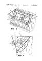
- FIG. 5is a view in perspective, with parts broken away of a modified filter assembly in accordance with the invention.
- a riding power sweeper embodying the inventionis indicated at 10.
- the machineincludes a frame or body 12 with intermediate wheels 14 and a central, rear wheel 16 which is steered by a steering wheel 18 located in front of an operator's seat 20.
- a curb or side broom(not shown) can be located in front of the wheel 14, as is known in the art, and a main, rotary drum broom 22 is located between and immediately to the rear of the wheels 14.
- a dirt and debris-receiving hopper 24is located at a forward portion of the machine to receive dirt and debris from the drum broom 22.
- the hopperhas a bottom 26 (FIG. 2), a rear wall 28, side walls 30, and a front wall 32.
- the rear wall 28is contoured to fit with a partition extending across the machine in front of the operator's location.
- the wall 28has a lower opening 34 to receive dirt and debris from the drum broom 22 with the periphery of this opening sealing with rubber flaps on a wall forming a plenum chamber around the main broom.
- the rear wall 28also has an upper opening 36 which communicates with a vacuum blower 38 which establishes a flow of air and air-borne dirt through the inlet 34, through a dirt and debris chamber 40, through a filter assembly indicated at 42, and through an exhaust chamber 44.
- the filter assembly 42divides the interior of the hopper 24 into the dirt and debris chamber 40 and the exhaust chamber 44.
- the hopper 24has a top 46 with a front section 48 over the dirt and debris chamber 40 and a rear section 50 over the exhaust chamber 44.
- the sectionsare connected by a hinge 52 and the rear section 50 is held down by at least one resilient latch 54 (FIG. 1) cooperating with a catch 56 (FIG. 3) on each of the hopper side walls 30.
- Filter meansis supported against the flanges 62, 66, 68, and 70.
- the filter meansconstitutes two separate filters 72 each including rectangular frames 74 and filter media 76.
- the filter mediaincludes pleated standard filter material backed up on the downstream or clean side by perforate metal screens.
- the filter frames 74are sealed on the supporting frame by gasket strips 78.
- the filters 72are held against the supporting flanges in the embodiment of FIGS. 3 and 4 by a holding frame 80 having side frame members 82, a lower longitudinal frame member 84, and an upper longitudinal frame member 86, all of square tubular construction, in this instance.
- the lower longitudinal frame member 84has two spaced ears 88 affixed thereto and pivotally connected to brackets 90 by pins 92, the brackets being affixed, as by welding, to the rear hopper wall 28.
- a combination holding and mounting plate 94extends between intermediate portions of the longitudinal frame members 84 and 86 and aids in holding portions of the filter 72 in place, particularly against the intermediate strap 70.
- a mounting bracket 96 of generally semi-circular configurationis affixed to a central portion of the mounting plate 94 by fasteners 98. The bracket 96 securely holds an electric motor 100 against the mounting plate 94.
- An eccentric weight 102is affixed to a drive shaft 104 of the motor 100 and shakes the motor 100, as well as the mounting plate 94 and the overall holding frame 80 when the drive shaft 104 is rotated. This causes dirt collected by the filter media 76 to fall out onto a collecting plate 106 in the hopper chamber 40.
- the hopper 24When the hopper 24 is emptied from a low dumping position, it is turned in a counterclockwise direction as viewed in FIG. 2 with dirt and debris in the chamber 40 emptying out the inlet opening 34 and with dirt collected on the plate 106 emptying out an elongate opening 108 in the rear wall 28 above the opening 34.
- the hopperWhen the hopper is designed to be emptied from a high dumping position, it is raised and turned in a clockwise direction with the chamber 40 emptied through the top with the top section 48 opening by gravity when the hopper is moved beyond an over-center position. At that time, the dirt collected on the plate 106 will also empty out through an upper opening 110 between the upper end of the plate 106 and the filter assembly 42, with the opening 108 in that instance being sealed off.
- the holding frame 80must be capable of being readily removable from the filters in order to replace them, as required from time to time.
- connecting means for holding the holding frame 80 against the filterscomprises a latch member 112 having a main portion 114 and an upper, angular end portion 116.
- the lower end of the main portion 114 of the latch member 112has a hole through which an L-shaped handle 118 having a threaded end 120 is received.
- the end 120is turned into a nut 122 affixed, as by welding, to the back of the mounting plate 94.
- An upper nut 124is threaded on an upper portion of the threaded end 120 of the handle 118 and turns with the handle 118.
- the nut 124firmly contacts the portion 114 of the latch 112 and firmly holds it in place, with the upper end 116 under the flange 60 of the strip 58. This provides ample force to hold the holding frame 80 against the filter 72 with the latch 112 being somewhat resilient and under stress.
- the handle 118is turned in a counterclockwise direction, the nut 124 moves with it and away from the latch portion 114. This provides sufficient play in the latch 112 to enable it to be swung out to the side and to move the end portion 116 away from under the flange 60.
- the nut 124can simply be a flange on the handle or a washer welded thereto, by way of example.
- a holding frame 126is substantially the same as the holding frame 80 but is somewhat smaller, having shorter end frame members 128, shorter upper and lower longitudinal frame members 130 and 132, and a shorter mounting plate 134. Intermediate portions of the end frame members 128 have outwardly-extending ears 136 which are pivotally connected by pins 138 to ends of pivot links 140. The other ends of the pivot links 140 are connected by an elongate rod 142 which also extends through the pivot links and has the ends supported by brackets 144. The brackets 144 are suitably affixed to the rear wall 28 of the hopper 24 as by fasteners 146.
- coil springs 148are connected between the pivot links 140 and the brackets 144, as by projecting pins 150 and 152 which are positioned so that the springs are located below the rod 142 when the holding frame 126 is in contact with the filters 72. Tension on the springs 148 thus urges the holding frame 126 further in a clockwise direction, as viewed in FIG. 6, to urge the frame 126 tightly against the filters.
- the frame 126When the filters 72 are to be removed and replaced, the frame 126 is swung to an upper dotted line position near the rear wall 28, as viewed in FIG. 6, to provide ready accessibility to the filters 72. At this time, the coil spring 148 is located above the elongate rod 142 and thereby urges the holding frame in a counterclockwise direction away from the filters.
- the connecting means of FIGS. 5 and 6enables the filters to be tightly held against the supporting frame or flanges and yet to be readily moved to an out-of-the-way position for accessibility to the filters.
Landscapes
- Chemical & Material Sciences (AREA)
- Chemical Kinetics & Catalysis (AREA)
- Engineering & Computer Science (AREA)
- Mechanical Engineering (AREA)
- Architecture (AREA)
- Civil Engineering (AREA)
- Structural Engineering (AREA)
- Filtering Of Dispersed Particles In Gases (AREA)
Abstract
Description
Claims (14)
Priority Applications (1)
| Application Number | Priority Date | Filing Date | Title |
|---|---|---|---|
| US06/256,526US4328014A (en) | 1981-04-22 | 1981-04-22 | Sweeper hopper with filter assembly |
Applications Claiming Priority (1)
| Application Number | Priority Date | Filing Date | Title |
|---|---|---|---|
| US06/256,526US4328014A (en) | 1981-04-22 | 1981-04-22 | Sweeper hopper with filter assembly |
Publications (1)
| Publication Number | Publication Date |
|---|---|
| US4328014Atrue US4328014A (en) | 1982-05-04 |
Family
ID=22972563
Family Applications (1)
| Application Number | Title | Priority Date | Filing Date |
|---|---|---|---|
| US06/256,526Expired - LifetimeUS4328014A (en) | 1981-04-22 | 1981-04-22 | Sweeper hopper with filter assembly |
Country Status (1)
| Country | Link |
|---|---|
| US (1) | US4328014A (en) |
Cited By (33)
| Publication number | Priority date | Publication date | Assignee | Title |
|---|---|---|---|---|
| US4514875A (en)* | 1983-03-16 | 1985-05-07 | Mcgraw-Edison Company | High capacity filter for floor cleaning machines and the like |
| EP0135787A3 (en)* | 1983-09-12 | 1985-12-04 | Tennant Company | Walk behind floor maintenance machine |
| US4571771A (en)* | 1984-08-27 | 1986-02-25 | Tennant Company | Sweeper with fire control |
| US4708723A (en)* | 1986-06-30 | 1987-11-24 | Howeth David Franklin | Rotary broom sweeper hopper |
| US4756727A (en)* | 1985-07-19 | 1988-07-12 | Howeth David Franklin | Horizontally mounted cylindrical segmented bore pleated filter system for rotary broom sweepers |
| US4790865A (en)* | 1986-05-30 | 1988-12-13 | Demarco Thomas | Two compartment industrial dust collector |
| US4842624A (en)* | 1988-05-19 | 1989-06-27 | Barton Ronald R | Apparatus for cleaning air filters |
| US4961762A (en)* | 1988-12-09 | 1990-10-09 | Howeth David Franklin | Structurally reinforced, self-aligning panel filter apparatus with associated clamping, face sealing and backflushing structure |
| US5194077A (en)* | 1990-03-20 | 1993-03-16 | Clarke Industries, Inc. | Dual chamber filter assembly with shaker |
| US5647093A (en)* | 1996-06-18 | 1997-07-15 | Tennant Company | Sweeper with dual seal filter |
| EP0878583A1 (en)* | 1996-04-15 | 1998-11-18 | Tennant Company | Sweeper and filter with electromagnetic filter cleaning |
| US6202765B1 (en)* | 1998-03-13 | 2001-03-20 | Tamrock Voest-Alpine Bergtechnik Gesellschaft M.B.H. | Device having a filter, a filter vibrating means and a scraper used for sucking off drillings |
| US6444003B1 (en) | 2001-01-08 | 2002-09-03 | Terry Lee Sutcliffe | Filter apparatus for sweeper truck hopper |
| US6569217B1 (en) | 2000-05-10 | 2003-05-27 | Thomas M. DeMarco | Industrial dust collector with multiple filter compartments |
| US6735814B2 (en) | 2000-10-05 | 2004-05-18 | Mister Services, Inc. | Apparatus for cleaning hard-to-reach areas |
| US20050091784A1 (en)* | 2003-08-05 | 2005-05-05 | Daniel Bone | Self-cleaning vacuum cleaner and receptacle therefor |
| US20050274094A1 (en)* | 2003-03-17 | 2005-12-15 | Demarco Thomas M | Vacuum loader |
| US20060207230A1 (en)* | 2003-03-17 | 2006-09-21 | Demarco Maxvac Corporation | Vacuum loader with filter doors |
| US20070000219A1 (en)* | 2005-06-30 | 2007-01-04 | Park Chan J | Air purifier |
| EP1818000A1 (en)* | 2001-09-07 | 2007-08-15 | Hako-Werke GMBH | Ground surface cleaning machine with filter cleaning means |
| US20080115317A1 (en)* | 2006-11-20 | 2008-05-22 | Phelan Katherine E | Wet And/Or Dry Vacuum With Floor Collector |
| US20090282641A1 (en)* | 2008-05-16 | 2009-11-19 | John Black | Filtering means and floor-sweeping machine provided with such means |
| US20110203062A1 (en)* | 2010-02-23 | 2011-08-25 | Burenga Thomas I | Rotary broom with gearbox drive |
| USD654234S1 (en) | 2010-12-08 | 2012-02-14 | Karcher North America, Inc. | Vacuum bag |
| US8887340B2 (en) | 2003-05-14 | 2014-11-18 | Kärcher North America, Inc. | Floor cleaning apparatus |
| US9015887B1 (en) | 2003-05-14 | 2015-04-28 | Kärcher North America, Inc. | Floor treatment apparatus |
| EP2873361A1 (en)* | 2013-11-15 | 2015-05-20 | Nilfisk Advance A/S | Dirt suction device with a hinged flap |
| US9038236B2 (en) | 2012-04-25 | 2015-05-26 | Shop Vac Corporation | Filter shaker |
| US9700824B2 (en) | 2011-04-20 | 2017-07-11 | Nilfisk, Inc. | Filter shaker system and method |
| US20170326489A1 (en)* | 2016-05-16 | 2017-11-16 | Bitfury Group Limited | Filter for immersion cooling apparatus |
| USD907868S1 (en) | 2019-01-24 | 2021-01-12 | Karcher North America, Inc. | Floor cleaner |
| CN113152239A (en)* | 2021-03-17 | 2021-07-23 | 中国五冶集团有限公司 | Pavement flatness control device |
| US12070181B2 (en) | 2017-05-04 | 2024-08-27 | Alfred Kärcher SE & Co. KG | Floor cleaning appliance and method for cleaning a floor surface |
Citations (8)
| Publication number | Priority date | Publication date | Assignee | Title |
|---|---|---|---|---|
| US1598644A (en)* | 1921-10-07 | 1926-09-07 | Oscar V Greene | Gas-cleaning apparatus |
| US2784440A (en)* | 1955-05-26 | 1957-03-12 | Wayne Manufacturing Co | Industrial sweeping machines |
| US3484889A (en)* | 1967-09-25 | 1969-12-23 | Scott & Fetzer Co | Sweeper filter |
| US3486309A (en)* | 1965-11-17 | 1969-12-30 | Parks Cramer Ltd | Fiber waste disposal system for textile machines |
| US3587213A (en)* | 1970-03-26 | 1971-06-28 | Wayne Manufacturing Co | Street sweeper filter cleaning system |
| US3928008A (en)* | 1974-08-05 | 1975-12-23 | Ross K Petersen | Filtering apparatus |
| US4002443A (en)* | 1975-03-31 | 1977-01-11 | Massey-Ferguson Inc. | Air filter clamping mechanism for cab |
| US4258451A (en)* | 1979-07-23 | 1981-03-31 | Tennant Company | Surface sweeping machine |
- 1981
- 1981-04-22USUS06/256,526patent/US4328014A/ennot_activeExpired - Lifetime
Patent Citations (8)
| Publication number | Priority date | Publication date | Assignee | Title |
|---|---|---|---|---|
| US1598644A (en)* | 1921-10-07 | 1926-09-07 | Oscar V Greene | Gas-cleaning apparatus |
| US2784440A (en)* | 1955-05-26 | 1957-03-12 | Wayne Manufacturing Co | Industrial sweeping machines |
| US3486309A (en)* | 1965-11-17 | 1969-12-30 | Parks Cramer Ltd | Fiber waste disposal system for textile machines |
| US3484889A (en)* | 1967-09-25 | 1969-12-23 | Scott & Fetzer Co | Sweeper filter |
| US3587213A (en)* | 1970-03-26 | 1971-06-28 | Wayne Manufacturing Co | Street sweeper filter cleaning system |
| US3928008A (en)* | 1974-08-05 | 1975-12-23 | Ross K Petersen | Filtering apparatus |
| US4002443A (en)* | 1975-03-31 | 1977-01-11 | Massey-Ferguson Inc. | Air filter clamping mechanism for cab |
| US4258451A (en)* | 1979-07-23 | 1981-03-31 | Tennant Company | Surface sweeping machine |
Cited By (51)
| Publication number | Priority date | Publication date | Assignee | Title |
|---|---|---|---|---|
| US4514875A (en)* | 1983-03-16 | 1985-05-07 | Mcgraw-Edison Company | High capacity filter for floor cleaning machines and the like |
| EP0135787A3 (en)* | 1983-09-12 | 1985-12-04 | Tennant Company | Walk behind floor maintenance machine |
| US4580313A (en)* | 1983-09-12 | 1986-04-08 | Tennant Company | Walk behind floor maintenance machine |
| US4571771A (en)* | 1984-08-27 | 1986-02-25 | Tennant Company | Sweeper with fire control |
| US4756727A (en)* | 1985-07-19 | 1988-07-12 | Howeth David Franklin | Horizontally mounted cylindrical segmented bore pleated filter system for rotary broom sweepers |
| US4790865A (en)* | 1986-05-30 | 1988-12-13 | Demarco Thomas | Two compartment industrial dust collector |
| US4708723A (en)* | 1986-06-30 | 1987-11-24 | Howeth David Franklin | Rotary broom sweeper hopper |
| US4842624A (en)* | 1988-05-19 | 1989-06-27 | Barton Ronald R | Apparatus for cleaning air filters |
| US4961762A (en)* | 1988-12-09 | 1990-10-09 | Howeth David Franklin | Structurally reinforced, self-aligning panel filter apparatus with associated clamping, face sealing and backflushing structure |
| US5194077A (en)* | 1990-03-20 | 1993-03-16 | Clarke Industries, Inc. | Dual chamber filter assembly with shaker |
| EP0878583A1 (en)* | 1996-04-15 | 1998-11-18 | Tennant Company | Sweeper and filter with electromagnetic filter cleaning |
| US5647093A (en)* | 1996-06-18 | 1997-07-15 | Tennant Company | Sweeper with dual seal filter |
| US6202765B1 (en)* | 1998-03-13 | 2001-03-20 | Tamrock Voest-Alpine Bergtechnik Gesellschaft M.B.H. | Device having a filter, a filter vibrating means and a scraper used for sucking off drillings |
| US6569217B1 (en) | 2000-05-10 | 2003-05-27 | Thomas M. DeMarco | Industrial dust collector with multiple filter compartments |
| US6735814B2 (en) | 2000-10-05 | 2004-05-18 | Mister Services, Inc. | Apparatus for cleaning hard-to-reach areas |
| US6444003B1 (en) | 2001-01-08 | 2002-09-03 | Terry Lee Sutcliffe | Filter apparatus for sweeper truck hopper |
| EP1818000A1 (en)* | 2001-09-07 | 2007-08-15 | Hako-Werke GMBH | Ground surface cleaning machine with filter cleaning means |
| US20060207230A1 (en)* | 2003-03-17 | 2006-09-21 | Demarco Maxvac Corporation | Vacuum loader with filter doors |
| US20050274094A1 (en)* | 2003-03-17 | 2005-12-15 | Demarco Thomas M | Vacuum loader |
| US9730566B2 (en) | 2003-05-14 | 2017-08-15 | Kärcher North America, Inc. | Floor treatment apparatus |
| US10555657B2 (en) | 2003-05-14 | 2020-02-11 | Kärcher North America, Inc. | Floor treatment apparatus |
| US9757005B2 (en) | 2003-05-14 | 2017-09-12 | Kärcher North America, Inc. | Floor treatment apparatus |
| US8887340B2 (en) | 2003-05-14 | 2014-11-18 | Kärcher North America, Inc. | Floor cleaning apparatus |
| US9510721B2 (en) | 2003-05-14 | 2016-12-06 | Karcher North America, Inc. | Floor cleaning apparatus |
| US9451861B2 (en) | 2003-05-14 | 2016-09-27 | Kärcher North America, Inc. | Floor treatment apparatus |
| US9192276B2 (en) | 2003-05-14 | 2015-11-24 | Karcher North America, Inc. | Floor cleaning apparatus |
| US9015887B1 (en) | 2003-05-14 | 2015-04-28 | Kärcher North America, Inc. | Floor treatment apparatus |
| EP1504710A3 (en)* | 2003-08-05 | 2006-03-22 | BLACK & DECKER INC. | Self-cleaning vacuum cleaner and receptacle therefor |
| US7386916B2 (en) | 2003-08-05 | 2008-06-17 | Black & Decker Inc. | Self-cleaning vacuum cleaner and receptacle therefor |
| US20050091784A1 (en)* | 2003-08-05 | 2005-05-05 | Daniel Bone | Self-cleaning vacuum cleaner and receptacle therefor |
| US20070000219A1 (en)* | 2005-06-30 | 2007-01-04 | Park Chan J | Air purifier |
| US7877839B2 (en) | 2006-11-20 | 2011-02-01 | Black & Decker Inc. | Wet and/or dry vacuum with floor collector |
| US20110094053A1 (en)* | 2006-11-20 | 2011-04-28 | Black & Decker Inc. | Wet And/Or Dry Vacuum With Floor Collector |
| US20080115317A1 (en)* | 2006-11-20 | 2008-05-22 | Phelan Katherine E | Wet And/Or Dry Vacuum With Floor Collector |
| US8037570B2 (en) | 2006-11-20 | 2011-10-18 | Black & Decker Inc. | Wet and/or dry vacuum with floor collector |
| US20090282641A1 (en)* | 2008-05-16 | 2009-11-19 | John Black | Filtering means and floor-sweeping machine provided with such means |
| EP2119389A3 (en)* | 2008-05-16 | 2016-04-13 | Nilfisk-Advance A/S | Improved filtering means and floor-sweeping machine provided with such means |
| US8161598B2 (en)* | 2008-05-16 | 2012-04-24 | Nilfisk-Advance Spa | Filtering means and floor-sweeping machine provided with such means |
| US8117705B2 (en) | 2010-02-23 | 2012-02-21 | Worksaver, Inc. | Rotary broom with gearbox drive |
| US20110203062A1 (en)* | 2010-02-23 | 2011-08-25 | Burenga Thomas I | Rotary broom with gearbox drive |
| USD654234S1 (en) | 2010-12-08 | 2012-02-14 | Karcher North America, Inc. | Vacuum bag |
| US9700824B2 (en) | 2011-04-20 | 2017-07-11 | Nilfisk, Inc. | Filter shaker system and method |
| EP2699331B1 (en)* | 2011-04-20 | 2019-12-04 | Nilfisk A/S | Filter and filter shaker system |
| US9038236B2 (en) | 2012-04-25 | 2015-05-26 | Shop Vac Corporation | Filter shaker |
| US10045673B2 (en) | 2013-11-15 | 2018-08-14 | Nilfisk-Advance A/S | Vacuum cleaner with hinged flap |
| EP2873361A1 (en)* | 2013-11-15 | 2015-05-20 | Nilfisk Advance A/S | Dirt suction device with a hinged flap |
| US20170326489A1 (en)* | 2016-05-16 | 2017-11-16 | Bitfury Group Limited | Filter for immersion cooling apparatus |
| US10765983B2 (en)* | 2016-05-16 | 2020-09-08 | Bitfury Ip B.V. | Filter for immersion cooling apparatus |
| US12070181B2 (en) | 2017-05-04 | 2024-08-27 | Alfred Kärcher SE & Co. KG | Floor cleaning appliance and method for cleaning a floor surface |
| USD907868S1 (en) | 2019-01-24 | 2021-01-12 | Karcher North America, Inc. | Floor cleaner |
| CN113152239A (en)* | 2021-03-17 | 2021-07-23 | 中国五冶集团有限公司 | Pavement flatness control device |
Similar Documents
| Publication | Publication Date | Title |
|---|---|---|
| US4328014A (en) | Sweeper hopper with filter assembly | |
| US4514875A (en) | High capacity filter for floor cleaning machines and the like | |
| US5194077A (en) | Dual chamber filter assembly with shaker | |
| US3747156A (en) | Filter chamber for scraping machine | |
| US4894881A (en) | Wet/dry vacuum machine | |
| JP2933467B2 (en) | Direct forward throw sweeper | |
| US4580313A (en) | Walk behind floor maintenance machine | |
| US6598263B2 (en) | Vacuum cleaner dirt collecting system with filter cleaning devices | |
| US4258451A (en) | Surface sweeping machine | |
| US6428590B1 (en) | Filter system for mobile debris collection machine | |
| FR2594709A1 (en) | AIR FILTRATION APPARATUS PROVIDED WITH AN IMPACT CLEANING MECHANISM OF THE FILTRATION DEVICE | |
| CN1211907A (en) | Apparatus for cleaning floors, carpets and like | |
| US5647093A (en) | Sweeper with dual seal filter | |
| US4219901A (en) | Riding sweeper | |
| US4708723A (en) | Rotary broom sweeper hopper | |
| EP0163678B1 (en) | Vacuum cleaner filter | |
| US8099828B2 (en) | External filter chamber | |
| JP2850409B2 (en) | Filter dust removal equipment for floor cleaning vehicles | |
| JP3632370B2 (en) | Filter dust remover for floor cleaning vehicles | |
| EP2262955B1 (en) | Mobile surface maintenance machine | |
| EP0857031B1 (en) | Suction sweeping machine | |
| GB2295971A (en) | Filters for air and gas cleaning | |
| JPH0644Y2 (en) | Filter mounting structure for floor cleaning vehicles | |
| JPS631402B2 (en) | ||
| US7896936B2 (en) | Filter cleaning apparatus |
Legal Events
| Date | Code | Title | Description |
|---|---|---|---|
| AS | Assignment | Owner name:SCOTT & FETZER COMPANY, THE, LAKEWOOD, OH, A CORP. Free format text:ASSIGNMENT OF ASSIGNORS INTEREST.;ASSIGNORS:BURGOON JACK L.;KNOWLTON CHRISTOPHER M.;REEL/FRAME:003881/0013 Effective date:19810410 Owner name:SCOTT & FETZER COMPANY, THE, A CORP. OF OH, OHIO Free format text:ASSIGNMENT OF ASSIGNORS INTEREST;ASSIGNORS:BURGOON JACK L.;KNOWLTON CHRISTOPHER M.;REEL/FRAME:003881/0013 Effective date:19810410 | |
| STCF | Information on status: patent grant | Free format text:PATENTED CASE | |
| AS | Assignment | Owner name:MCGRAW-EDISON COMPANY ONE CONTINENTAL TOWERS 1701 Free format text:ASSIGNMENT OF ASSIGNORS INTEREST.;ASSIGNOR:SCOTT & FETZER COMPANY THE AN OH CORP;REEL/FRAME:004287/0004 Effective date:19840430 | |
| AS | Assignment | Owner name:COOPER INDUSTRIES, INC., 1001 FANNIN, HOUSTON, TEX Free format text:ASSIGNMENT OF ASSIGNORS INTEREST.;ASSIGNOR:MCGRAW-EDISON COMPANY;REEL/FRAME:004475/0965 Effective date:19851104 | |
| FEPP | Fee payment procedure | Free format text:SURCHARGE FOR LATE PAYMENT, PL 96-517 (ORIGINAL EVENT CODE: M176); ENTITY STATUS OF PATENT OWNER: LARGE ENTITY | |
| MAFP | Maintenance fee payment | Free format text:PAYMENT OF MAINTENANCE FEE, 4TH YEAR, PL 96-517 (ORIGINAL EVENT CODE: M170); ENTITY STATUS OF PATENT OWNER: LARGE ENTITY Year of fee payment:4 | |
| AS | Assignment | Owner name:COOPER INDUSTRIES, INC., 1001 FANNIN, SUITE 4000, Free format text:ASSIGNMENT OF ASSIGNORS INTEREST.;ASSIGNOR:COOPER INDUSTRIES, INC., A OH. CORP.;REEL/FRAME:004657/0666 Effective date:19870108 Owner name:COOPER INDUSTRIES, INC., A CORP. OF DE.,TEXAS Free format text:ASSIGNMENT OF ASSIGNORS INTEREST;ASSIGNOR:COOPER INDUSTRIES, INC., A OH. CORP.;REEL/FRAME:004657/0666 Effective date:19870108 | |
| MAFP | Maintenance fee payment | Free format text:PAYMENT OF MAINTENANCE FEE, 8TH YEAR, PL 96-517 (ORIGINAL EVENT CODE: M171); ENTITY STATUS OF PATENT OWNER: LARGE ENTITY Year of fee payment:8 | |
| FEPP | Fee payment procedure | Free format text:PAYOR NUMBER ASSIGNED (ORIGINAL EVENT CODE: ASPN); ENTITY STATUS OF PATENT OWNER: LARGE ENTITY | |
| AS | Assignment | Owner name:WELLS FARGO BANK, N.A., STATELESS Free format text:SECURITY INTEREST;ASSIGNOR:CLARKE INDUSTRIES, INC., A CORP. OF DE;REEL/FRAME:006264/0108 Effective date:19920303 | |
| MAFP | Maintenance fee payment | Free format text:PAYMENT OF MAINTENANCE FEE, 12TH YEAR, LARGE ENTITY (ORIGINAL EVENT CODE: M185); ENTITY STATUS OF PATENT OWNER: LARGE ENTITY Year of fee payment:12 | |
| AS | Assignment | Owner name:CLARKE INDUSTRIES, INC., MISSOURI Free format text:RELEASE BY SECURED PARTY;ASSIGNOR:WELLS FARGO BANK, N.A.;REEL/FRAME:006865/0170 Effective date:19940201 Owner name:STOODY DELORO STELLITE, INC., MISSOURI Free format text:RELEASE BY SECURED PARTY;ASSIGNOR:WELLS FARGO BANK, N.A.;REEL/FRAME:006865/0170 Effective date:19940201 Owner name:VICTOR EQUIPMENT COMPANY, INC., MISSOURI Free format text:RELEASE BY SECURED PARTY;ASSIGNOR:WELLS FARGO BANK, N.A.;REEL/FRAME:006865/0170 Effective date:19940201 Owner name:THERMAL DYNAMICS CORPORATION, MISSOURI Free format text:RELEASE BY SECURED PARTY;ASSIGNOR:WELLS FARGO BANK, N.A.;REEL/FRAME:006865/0170 Effective date:19940201 Owner name:BANKERS TRUST COMPANY, NEW YORK Free format text:SECURITY INTEREST;ASSIGNORS:ARCAIR COMPANY;CLARKE INDUSTRIES, INC.;COYNE CYLINDER COMPANY;AND OTHERS;REEL/FRAME:006865/0142 Effective date:19940201 Owner name:TWECO PRODUCTS, INC., MISSOURI Free format text:RELEASE BY SECURED PARTY;ASSIGNOR:WELLS FARGO BANK, N.A.;REEL/FRAME:006865/0170 Effective date:19940201 Owner name:COYNE CYLINDER COMPANY, MISSOURI Free format text:RELEASE BY SECURED PARTY;ASSIGNOR:WELLS FARGO BANK, N.A.;REEL/FRAME:006865/0170 Effective date:19940201 Owner name:MARISON CYLINDER, MISSOURI Free format text:RELEASE BY SECURED PARTY;ASSIGNOR:WELLS FARGO BANK, N.A.;REEL/FRAME:006865/0170 Effective date:19940201 Owner name:ARCAIR COMPANY, MISSOURI Free format text:RELEASE BY SECURED PARTY;ASSIGNOR:WELLS FARGO BANK, N.A.;REEL/FRAME:006865/0170 Effective date:19940201 |