US4327746A - Blood extraction device - Google Patents
Blood extraction deviceDownload PDFInfo
- Publication number
- US4327746A US4327746AUS06/127,709US12770980AUS4327746AUS 4327746 AUS4327746 AUS 4327746AUS 12770980 AUS12770980 AUS 12770980AUS 4327746 AUS4327746 AUS 4327746A
- Authority
- US
- United States
- Prior art keywords
- needle
- blood sample
- sample tube
- receptacle
- blood
- Prior art date
- Legal status (The legal status is an assumption and is not a legal conclusion. Google has not performed a legal analysis and makes no representation as to the accuracy of the status listed.)
- Expired - Lifetime
Links
- 239000008280bloodSubstances0.000titleclaimsabstractdescription111
- 210000004369bloodAnatomy0.000titleclaimsabstractdescription111
- 238000000605extractionMethods0.000titleclaimsabstractdescription41
- 239000012528membraneSubstances0.000claimsabstractdescription28
- 238000007789sealingMethods0.000claimsabstractdescription13
- 239000000463materialSubstances0.000claimsdescription5
- 230000000717retained effectEffects0.000claims2
- 230000000149penetrating effectEffects0.000claims1
- 210000003462veinAnatomy0.000description8
- 230000000694effectsEffects0.000description7
- 230000035515penetrationEffects0.000description5
- 239000000443aerosolSubstances0.000description4
- 238000003780insertionMethods0.000description4
- 230000037431insertionEffects0.000description4
- 238000000034methodMethods0.000description3
- 230000001681protective effectEffects0.000description3
- 241000251468ActinopterygiiSpecies0.000description2
- 230000006835compressionEffects0.000description2
- 238000007906compressionMethods0.000description2
- 238000013461designMethods0.000description2
- 239000004743PolypropyleneSubstances0.000description1
- 239000011324beadSubstances0.000description1
- 238000013270controlled releaseMethods0.000description1
- 238000012864cross contaminationMethods0.000description1
- 230000003247decreasing effectEffects0.000description1
- 238000011161developmentMethods0.000description1
- 239000000284extractSubstances0.000description1
- 208000015181infectious diseaseDiseases0.000description1
- 239000007788liquidSubstances0.000description1
- 238000004519manufacturing processMethods0.000description1
- -1polypropylenePolymers0.000description1
- 229920001155polypropylenePolymers0.000description1
- 229920002223polystyrenePolymers0.000description1
- 239000003566sealing materialSubstances0.000description1
- 239000007779soft materialSubstances0.000description1
- 229920002994synthetic fiberPolymers0.000description1
- 238000012360testing methodMethods0.000description1
Images


Classifications
- A—HUMAN NECESSITIES
- A61—MEDICAL OR VETERINARY SCIENCE; HYGIENE
- A61B—DIAGNOSIS; SURGERY; IDENTIFICATION
- A61B5/00—Measuring for diagnostic purposes; Identification of persons
- A61B5/15—Devices for taking samples of blood
- A61B5/153—Devices specially adapted for taking samples of venous or arterial blood, e.g. with syringes
- A61B5/154—Devices using pre-evacuated means
- A—HUMAN NECESSITIES
- A61—MEDICAL OR VETERINARY SCIENCE; HYGIENE
- A61B—DIAGNOSIS; SURGERY; IDENTIFICATION
- A61B5/00—Measuring for diagnostic purposes; Identification of persons
- A61B5/15—Devices for taking samples of blood
- A61B5/150007—Details
- A61B5/150015—Source of blood
- A61B5/15003—Source of blood for venous or arterial blood
- A—HUMAN NECESSITIES
- A61—MEDICAL OR VETERINARY SCIENCE; HYGIENE
- A61B—DIAGNOSIS; SURGERY; IDENTIFICATION
- A61B5/00—Measuring for diagnostic purposes; Identification of persons
- A61B5/15—Devices for taking samples of blood
- A61B5/150007—Details
- A61B5/150053—Details for enhanced collection of blood or interstitial fluid at the sample site, e.g. by applying compression, heat, vibration, ultrasound, suction or vacuum to tissue; for reduction of pain or discomfort; Skin piercing elements, e.g. blades, needles, lancets or canulas, with adjustable piercing speed
- A61B5/150061—Means for enhancing collection
- A61B5/150099—Means for enhancing collection by negative pressure, other than vacuum extraction into a syringe by pulling on the piston rod or into pre-evacuated tubes
- A—HUMAN NECESSITIES
- A61—MEDICAL OR VETERINARY SCIENCE; HYGIENE
- A61B—DIAGNOSIS; SURGERY; IDENTIFICATION
- A61B5/00—Measuring for diagnostic purposes; Identification of persons
- A61B5/15—Devices for taking samples of blood
- A61B5/150007—Details
- A61B5/150206—Construction or design features not otherwise provided for; manufacturing or production; packages; sterilisation of piercing element, piercing device or sampling device
- A61B5/150213—Venting means
- A—HUMAN NECESSITIES
- A61—MEDICAL OR VETERINARY SCIENCE; HYGIENE
- A61B—DIAGNOSIS; SURGERY; IDENTIFICATION
- A61B5/00—Measuring for diagnostic purposes; Identification of persons
- A61B5/15—Devices for taking samples of blood
- A61B5/150007—Details
- A61B5/150206—Construction or design features not otherwise provided for; manufacturing or production; packages; sterilisation of piercing element, piercing device or sampling device
- A61B5/150221—Valves
- A—HUMAN NECESSITIES
- A61—MEDICAL OR VETERINARY SCIENCE; HYGIENE
- A61B—DIAGNOSIS; SURGERY; IDENTIFICATION
- A61B5/00—Measuring for diagnostic purposes; Identification of persons
- A61B5/15—Devices for taking samples of blood
- A61B5/150007—Details
- A61B5/150206—Construction or design features not otherwise provided for; manufacturing or production; packages; sterilisation of piercing element, piercing device or sampling device
- A61B5/150229—Pumps for assisting the blood sampling
- A—HUMAN NECESSITIES
- A61—MEDICAL OR VETERINARY SCIENCE; HYGIENE
- A61B—DIAGNOSIS; SURGERY; IDENTIFICATION
- A61B5/00—Measuring for diagnostic purposes; Identification of persons
- A61B5/15—Devices for taking samples of blood
- A61B5/150007—Details
- A61B5/150351—Caps, stoppers or lids for sealing or closing a blood collection vessel or container, e.g. a test-tube or syringe barrel
- A—HUMAN NECESSITIES
- A61—MEDICAL OR VETERINARY SCIENCE; HYGIENE
- A61B—DIAGNOSIS; SURGERY; IDENTIFICATION
- A61B5/00—Measuring for diagnostic purposes; Identification of persons
- A61B5/15—Devices for taking samples of blood
- A61B5/150007—Details
- A61B5/150374—Details of piercing elements or protective means for preventing accidental injuries by such piercing elements
- A61B5/150381—Design of piercing elements
- A61B5/150389—Hollow piercing elements, e.g. canulas, needles, for piercing the skin
- A61B5/150396—Specific tip design, e.g. for improved penetration characteristics
- A—HUMAN NECESSITIES
- A61—MEDICAL OR VETERINARY SCIENCE; HYGIENE
- A61B—DIAGNOSIS; SURGERY; IDENTIFICATION
- A61B5/00—Measuring for diagnostic purposes; Identification of persons
- A61B5/15—Devices for taking samples of blood
- A61B5/150007—Details
- A61B5/150374—Details of piercing elements or protective means for preventing accidental injuries by such piercing elements
- A61B5/150381—Design of piercing elements
- A61B5/150473—Double-ended needles, e.g. used with pre-evacuated sampling tubes
- A—HUMAN NECESSITIES
- A61—MEDICAL OR VETERINARY SCIENCE; HYGIENE
- A61B—DIAGNOSIS; SURGERY; IDENTIFICATION
- A61B5/00—Measuring for diagnostic purposes; Identification of persons
- A61B5/15—Devices for taking samples of blood
- A61B5/150007—Details
- A61B5/150374—Details of piercing elements or protective means for preventing accidental injuries by such piercing elements
- A61B5/150534—Design of protective means for piercing elements for preventing accidental needle sticks, e.g. shields, caps, protectors, axially extensible sleeves, pivotable protective sleeves
- A61B5/150572—Pierceable protectors, e.g. shields, caps, sleeves or films, e.g. for hygienic purposes
- A—HUMAN NECESSITIES
- A61—MEDICAL OR VETERINARY SCIENCE; HYGIENE
- A61B—DIAGNOSIS; SURGERY; IDENTIFICATION
- A61B5/00—Measuring for diagnostic purposes; Identification of persons
- A61B5/15—Devices for taking samples of blood
- A61B5/150007—Details
- A61B5/150732—Needle holders, for instance for holding the needle by the hub, used for example with double-ended needle and pre-evacuated tube
- B—PERFORMING OPERATIONS; TRANSPORTING
- B01—PHYSICAL OR CHEMICAL PROCESSES OR APPARATUS IN GENERAL
- B01L—CHEMICAL OR PHYSICAL LABORATORY APPARATUS FOR GENERAL USE
- B01L3/00—Containers or dishes for laboratory use, e.g. laboratory glassware; Droppers
- B01L3/50—Containers for the purpose of retaining a material to be analysed, e.g. test tubes
- B01L3/508—Containers for the purpose of retaining a material to be analysed, e.g. test tubes rigid containers not provided for above
- B01L3/5082—Test tubes per se
- B01L3/50825—Closing or opening means, corks, bungs
- B—PERFORMING OPERATIONS; TRANSPORTING
- B01—PHYSICAL OR CHEMICAL PROCESSES OR APPARATUS IN GENERAL
- B01L—CHEMICAL OR PHYSICAL LABORATORY APPARATUS FOR GENERAL USE
- B01L2200/00—Solutions for specific problems relating to chemical or physical laboratory apparatus
- B01L2200/06—Fluid handling related problems
- B01L2200/0689—Sealing
- B—PERFORMING OPERATIONS; TRANSPORTING
- B01—PHYSICAL OR CHEMICAL PROCESSES OR APPARATUS IN GENERAL
- B01L—CHEMICAL OR PHYSICAL LABORATORY APPARATUS FOR GENERAL USE
- B01L2300/00—Additional constructional details
- B01L2300/04—Closures and closing means
- B01L2300/041—Connecting closures to device or container
- B01L2300/044—Connecting closures to device or container pierceable, e.g. films, membranes
Definitions
- the present inventionis directed to a blood extraction device as described hereinafter, and in addition, a procedure for using it, and a device for execution of a procedural step in the use of the blood extraction device.
- Blood extraction devicesare generally known, for example see U.S. Pat. Nos. 2,460,641 and 3,136,440.
- the seal of the blood sample tubeconsists of a rubber stopper. If this stopper is opened in order to remove the extracted blood for further use or analysis, a certain momentary low pressure will occur at the surface of the blood sample, with the result that some drops of the blood sample may be scattered when the stopper is removed. This "aerosol" effect is reinforced by the elasticity of the stopper material when it is opened rapidly.
- the sealSince, in the case of the known devices, the vacuum is created already in the production stage, the seal must be designed so that it maintains the vacuum for a longer period of time.
- the rubber stoppermust be thick at the edge. Frequently, penetration by a hollow needle requires too much force. For this reason, a recess is provided in the center of the stopper, in order to have a thinner place for penetration. Thus, the needle cannot be inserted close to the side, i.e. eccentrically, which would be desirable in order to make a "flatter” insertion into the patient's vein.
- the initially uniform vacuummay have decreased so that there is no guarantee of constant and uniform speed of blood extraction, nor for a constantly uniform volume of the extracted sample.
- the present inventionprovides a new, unobvious and advantageous blood extraction device.
- the present inventioneliminates the dangers of an "aerosol" effect during the opening of the blood sample tube.
- sealing of the blood sample tubeis simplified and more reliable results are achieved as the vacuum in the blood sample tube is more uniform at the time of use.
- the inventionsolves the above-mentioned problem in a particularly simple manner by using a relatively thin and simple sealing material, the membrane, in combination with a screw closure.
- a relatively thin and simple sealing materialthe membrane
- Thisallows, for the first time, the application of a screw closure in a blood extraction system under vacuum of the above-mentioned nature, although the rubber stopper has been regarded as indispensable for the sake of penetration with a needle.
- the membranecan be manufactured of relatively thin and/or softer material, so that it is easier to penetrate and requires only approximately 1/3 of the force.
- the needlecan also be placed eccentrically.
- the designis simple when compared to blood extraction systems which, in principle, function as syringes in order to obtain a vacuum.
- a further advantage of the present inventionconcerns blood extraction under aspiration, that is under control of a negative pressure in the blood sample tube in a particularly simple manner.
- a rubber balloonis provided for this purpose.
- the rubber balloonmay also be used as a handle.
- a valveis provided between the rubber balloon and a second needle, which serves aspiration purposes. The valve prevents air pressure from entering the blood sample tube when the rubber balloon is compressed, and also activates the suction or negative pressure in the blood sample tube when the rubber balloon is released.
- the rubber balloonmay also be constructed in the shape of a fish bladder and located alongside and adjacent to the outside of the receptacle. In this manner, it is particularly simple to handle the device with a single hand.
- FIG. 1is a side elevation view partially in cross-section, of a blood extraction device in accordance with the present invention.
- FIG. 1ais a view, partially in cross-section, taken along line 1a--1a of FIG. 1.
- FIG. 2is an elevation view, partially in cross-section, of an embodiment of the present invention illustrating the elements of FIG. 1 in partially assembled form.
- FIG. 3is a view, partially in cross-section and partially in schematic form, illustrating a blood sample tube in accordance with the present invention being connected to an evacuation device in accordance with the present invention.
- FIGS. 4a, 4b and 4cillustrate another embodiment of the present invention, with FIG. 4a being a front elevation view looking down needle 107, FIG. 4b being a side elevation view partially in cross-section and FIG. 4c being a top elevation view of FIG. 4b.
- FIG. 5illustrates another embodiment of the present invention, and particularly illustrates a particular embodiment of a sealing membrane 218.
- FIG. 6illustrates another embodiment of the invention, particularly illustrating another form of a sealing membrane.
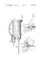
- FIG. 7is an elevation view, partially in cross-section, of another embodiment of the present invention.
- FIG. 8is an elevation view illustrating a manner of use of the apparatus of FIG. 7 in extracting blood from a vein.
- FIG. 9is an elevation view, partially in cross-section, of another embodiment of the present invention.
- FIG. 10is an elevation view illustrating a manner of use of the apparatus of FIG. 9 in extracting blood from a vein.
- the blood extraction deviceis comprised of a receptacle 1 and a blood sample tube 2.
- Receptacle 1has a hollow cylindrical shape and is open at its one end 3.
- receptacle 1is provided with threading 5, into which needle holder 6 is screwed, eccentrically as shown in FIG. 1a.
- Needle holder 6serves as a firm attachment for double-ended hollow needle 7, one end 8 of which is located, as shown, outside of receptacle 1 and is inserted into the vein of a person for purposes of blood extraction, and the other end 9 of which extends into the interior of hollow cylindrical space 10 of receptacle 1. That part of needle 7 which extends into the interior 10 of the receptacle is surrounded by protective cover 11 of easily penetrated, light, soft material.
- receptacle 1is provided with flange 12 which facilitates the handling during blood extraction.
- blood sample tube 2is manufactured of transparent synthetic material, e.g. polystyrol or polypropylene.
- Blood sample tube 2is provided with a screw closure, comprised of cap 14 screwed on to the left end, as seen in FIG. 1, of blood sample tube 2.
- Blood sample tube 2is provided with screw threads which mate with corresponding threading 15 of cap 14.
- cap 14is provided with an opening 16, the diameter of which is designed so that edge or rim 17, which extends from the outside inwardly and perpendicularly to the axis of blood sample tube 2, extends so far that it presses membrane 18 against the open front of blood sample tube 2 at its open end, left end seen in FIG. 1.
- Membrane 18is comprised of soft rubber, which has the characteristic that when a needle penetrates it and is removed again, the material closes again. Such materials are known in the art.
- the thickness of membrane 18amounts to 1.5 to 3 mm, preferably 2 mm.
- cap 14The exterior of cap 14 is cylindrically designed so that it fits into hollow cylindrical space 10 of receptacle 1.
- blood sample tube 2 with attached cap 14can be inserted into receptacle 1 as shown in FIG. 2.
- end 9 of needle 7penetrates membrane 18.
- a connectionis created between the interior of blood sample tube 2 and the opening of needle 7 at its end 8.
- protective cover 11 on tip 9 of needle 7is penetrated.
- protective cover 11compresses like a bellows.
- blood sample tubesare prepared in the manner shown in FIG. 2, where they are closed and vacuum sealed. They are initially not evacuated.
- the blood extraction device according to the present inventiondiffers from all known blood extraction systems working with a vacuum, insofar as blood sample tube 2 is first made available in a status of not being evacuated, i.e., it is marketed and delivered to the user not evacuated.
- blood sample tubes 2which have previously been tightly closed. This is accomplished in the manner shown in FIG. 31.
- the tightly closed, but not yet evacuated, blood sample tube 2is evacuated in a simple evacuation device.
- This evacuation device 19is comprised of a hollow needle 20, which is connected to a vacuum pump 22 via a line 21.
- the vacuum pump 22is activated by means of electrical motor 23, supplied with current via lines 24.
- evacuation device 19is provided with insertion funnel 25 surrounding the needle. Blood sample tube 2 can be inserted into the funnel so that end 26 of needle 20 penetrates membrane 18.
- working contact 31 in pressure meter 30will close, which working contact 31 interrupts line 24 via relay 32 and its rear contact 33, thus deactivating electrical motor 23 and, consequently, vacuum pump 22. Thereafter, blood sample tube 2 is removed from needle 20, and is then ready for use.
- Blood extraction from a patientproceeds in the following manner. First, one takes receptacle 1, where blood sample tube 2 is only inserted so far that membrane 18 is not yet penetrated, and point 8 is inserted into the vein of a patient. Then blood sample tube 2 is inserted further into interior space 10, until point 9 penetrates membrane 18. The vacuum in blood sample tube 2 extracts blood from the vein. When a sufficient quantity of blood has been extracted, blood sample tube 2 is removed from receptacle 1. Membrane 18 closes again, and the blood extraction procedure is complete. The blood sample can then be removed from blood sample tube 2 when cap 14 is removed.
- FIGS. 4a through 4cshow another embodiment.
- Receptacle 101is provided with two needles, namely first needle 107 and second needle 134.
- Needle 134transforms into hollow line 135, which first runs radially to the outside of receptacle 101 and then along the cylindrically outside wall.
- a blood sample tubeis inserted so far into cylindrical interior space 110 of receptacle 101 that the two needles 107 and 134 penetrate membrane 18 of blood sample tube 2, the blood extraction can be aided. If one sucks at the suction line, the vacuum in blood sample tube 2 is increased. If air is let in, blood extraction is terminated. In this manner it is possible to control the blood extraction process as desired.
- the blood extraction system of the present inventionis simplified over that of the prior art since the vacuum in blood extraction tube 2 only need be maintained for a short period of time, approximately the duration of one day and often less, since the vacuum in blood extraction tube 2 is created only relatively shortly before the use of the blood extraction system, as described in relation to FIG. 3.
- the resultis that one can be certain of the existence of a vacuum in blood extraction tube 2 at the time the blood extraction system of the present invention is being used.
- this vacuumalso has a very specific value. Thus, a particular rate of speed of blood extraction is guaranteed.
- Evacuation mechanism 19from the standpoint of cost, basically comprises the vacuum pump, which is relatively inexpensive and simple.
- the blood extraction systemin accordance with the present invention makes it possible to predesign the sealing, determined by the thickness of membrane 18 as well as the sealing surface and the contact pressure, in such a manner that the sealing need maintain the desired vacuum over only a relatively short period of time, approximately a maximum two or three days.
- Thisis advantageous in that the invention eliminates the traditionally used rubber stopper and uses a simple screw closure. The screw closure can be opened without the occurrence of an "aerosol" effect which occurs when a rubber stopper is removed.
- edge 217 of cap 214has a small, circumferencial path 239 with a relatively sharp edge which connects with the surface of membrane 218 and holds it in place. This may be the case when the membrane is so thin that it is drawn into blood sample tube 202, to the position indicated with a dotted line. In the middle, at the point where it is penetrated by needle 207, membrane 218 has a recess 240, so that needle 207 need only penetrate thin portion 241.
- the recess in membrane 318is much larger than in the embodiment of FIG. 5.
- needle 307is eccentrically placed in receptacle 301. This facilitates insertion into a vein.
- the blood extraction system according to FIG. 7represents a further development of the blood extraction device according to FIGS. 4a--4c. It is constituted by receptacle 101 and blood sample tube 2. Suction line 137 is connected with three-way valve 500 via connecting plug 138. A second opening 501 leads to connection 138. A third opening 502 communicates with the atmosphere. On connector 503, in which suction line 137 is provided, compressible rubber balloon 504 has been applied. After compression, it has the tendency to regain the round shape as illustrated. Thus, a pump effect can be obtained, which can be utilized for so-called aspiration, e.g. blood extraction with simultaneous creation of additional negative pressure in blood sample tube 2.
- aspiratione.g. blood extraction with simultaneous creation of additional negative pressure in blood sample tube 2.
- valve 500is designed as a double ball valve with two balls, 505 and 506, which are located in valve chambers 507 and 508. If rubber balloon 504 is compressed, an over-pressure occurs in suction line 137. Ball 505 in left-hand chamber 507 is pushed to valve seat 509 and closes it. Thus, no air can exit into line 135 and consequently not into blood sample tube 2. Simultaneously, right-hand ball 506 in chamber 508 is pressed against right-hand valve seat 510. However, valve seat 510 is not solidly formed but is provided with a slit 511 by means of which air can escape and enter the atmosphere via opening 502. When rubber balloon 504 is compressed, opening 501 is closed and thereby also the access to needle 134. The air which is dislocated when balloon 504 is compressed escapes into the atmosphere via opening 502.
- the negative pressure created in blood sample tube 2can be controlled by hand-operated release of rubber balloon 504.
- valve 500 as illustratedis merely a preferred embodiment and is not intended to limit the invention. Any suitable valve may be used which guarantees that only a negative pressure is created via hollow line 135 and second needle 134 in blood sample tube 2, and which ensures that no air is pushed into blood sample tube 2 when the rubber balloon is compressed.
- rubber balloon 504may also be utilized as a handle for easier operation of the blood extraction device for extracting blood from vein V of arm A.
- FIG. 9differs from that shown in FIG. 7 in that rubber balloon 515 is designed as a fish bladder and is adjacent to receptacle 101 in such a manner that it enables handling with only one hand in a particularly simple manner. This is shown in FIG. 10.
Landscapes
- Health & Medical Sciences (AREA)
- Life Sciences & Earth Sciences (AREA)
- Engineering & Computer Science (AREA)
- Hematology (AREA)
- General Health & Medical Sciences (AREA)
- Animal Behavior & Ethology (AREA)
- Pathology (AREA)
- Biomedical Technology (AREA)
- Heart & Thoracic Surgery (AREA)
- Medical Informatics (AREA)
- Molecular Biology (AREA)
- Surgery (AREA)
- Biophysics (AREA)
- Physics & Mathematics (AREA)
- Public Health (AREA)
- Veterinary Medicine (AREA)
- Manufacturing & Machinery (AREA)
- Chemical & Material Sciences (AREA)
- Analytical Chemistry (AREA)
- Clinical Laboratory Science (AREA)
- Chemical Kinetics & Catalysis (AREA)
- Dermatology (AREA)
- Pain & Pain Management (AREA)
- Measurement Of The Respiration, Hearing Ability, Form, And Blood Characteristics Of Living Organisms (AREA)
- Sampling And Sample Adjustment (AREA)
- Infusion, Injection, And Reservoir Apparatuses (AREA)
- Investigating Or Analysing Biological Materials (AREA)
Abstract
Description
Claims (6)
Applications Claiming Priority (5)
| Application Number | Priority Date | Filing Date | Title |
|---|---|---|---|
| DE19792908817DE2908817A1 (en) | 1979-03-07 | 1979-03-07 | Blood-taking appts. with cylindrical container and needle - has blood sampling tube closed by screwed cap pressing pierceable diaphragm against tube open=end |
| DE2908817 | 1979-03-07 | ||
| DE19792946660DE2946660A1 (en) | 1979-03-07 | 1979-11-19 | Blood sampler with needle and sample tube - having tube closed by screw cap with rim clipped diaphragm pierced by double end needle |
| DE2946660 | 1979-11-19 | ||
| DE19803029886DE3029886A1 (en) | 1979-03-07 | 1980-08-07 | BLOOD COLLECTION DEVICE |
Publications (1)
| Publication Number | Publication Date |
|---|---|
| US4327746Atrue US4327746A (en) | 1982-05-04 |
Family
ID=51703462
Family Applications (1)
| Application Number | Title | Priority Date | Filing Date |
|---|---|---|---|
| US06/127,709Expired - LifetimeUS4327746A (en) | 1979-03-07 | 1980-03-06 | Blood extraction device |
Country Status (4)
| Country | Link |
|---|---|
| US (1) | US4327746A (en) |
| EP (2) | EP0017728A3 (en) |
| JP (1) | JPS5755155A (en) |
| DE (2) | DE2946660A1 (en) |
Cited By (23)
| Publication number | Priority date | Publication date | Assignee | Title |
|---|---|---|---|---|
| AU580727B2 (en)* | 1983-01-27 | 1989-02-02 | C.A. Greiner & Sohne Gesellschaft M.B.H. | Blood sampling tube |
| WO1992016150A1 (en)* | 1991-03-19 | 1992-10-01 | Ob Tech | Cord cutter sampler |
| US5313969A (en)* | 1992-12-08 | 1994-05-24 | Hsieh Ch Ing Lung | Instant pressure-reducing process and device for a blood-gathering tube |
| US5507299A (en)* | 1994-06-13 | 1996-04-16 | Roland; Patricia D. | Multi-vial blood collection system |
| US5575796A (en)* | 1995-05-17 | 1996-11-19 | Utah Medical Products, Inc. | Umbilical cord cutter and sampler |
| SG93799A1 (en)* | 1995-08-30 | 2003-01-21 | Becton Dickinson Co | Alternate methods for filling glass capillary tubes |
| EP1300114A3 (en)* | 2001-10-06 | 2003-05-28 | Sarstedt AG & Co. | Evacuating device for a blood collection tube |
| US20030236497A1 (en)* | 2002-06-25 | 2003-12-25 | Radiometer Medical A/S | Sampler cap |
| US20050226772A1 (en)* | 2002-04-23 | 2005-10-13 | Idaho Technology, Inc. | Sample withdrawal and dispensing device |
| GB2418489A (en)* | 2002-04-23 | 2006-03-29 | Idaho Technology Inc | Sample withdrawal and dispensing device |
| US20170213618A1 (en)* | 2012-02-16 | 2017-07-27 | Yazaki Corporation | Sheet for wire harness, wire harness, and production method for wire harness |
| CN112058331A (en)* | 2020-09-15 | 2020-12-11 | 湖南力源健康发展有限公司 | Blood test tube with protect function |
| US11395611B2 (en) | 2012-05-30 | 2022-07-26 | Magnolia Medical Technologies, Inc. | Fluid diversion mechanism for bodily-fluid sampling |
| US11419531B2 (en)* | 2017-12-07 | 2022-08-23 | Magnolia Medical Technologies, Inc. | Fluid control devices and methods of using the same |
| US11529081B2 (en) | 2017-09-12 | 2022-12-20 | Magnolia Medical Technologies, Inc. | Fluid control devices and methods of using the same |
| US11589786B2 (en) | 2012-11-30 | 2023-02-28 | Magnolia Medical Technologies, Inc. | Syringe-based fluid diversion mechanism for bodily fluid sampling |
| US11737693B2 (en) | 2012-12-04 | 2023-08-29 | Magnolia Medical Technologies, Inc. | Sterile bodily-fluid collection device and methods |
| US11786155B2 (en) | 2019-02-08 | 2023-10-17 | Magnolia Medical Technologies, Inc. | Devices and methods for bodily fluid collection and distribution |
| US11819329B2 (en) | 2012-05-30 | 2023-11-21 | Magnolia Medical Technologies, Inc. | Fluid diversion mechanism for bodily-fluid sampling |
| US11857321B2 (en) | 2019-03-11 | 2024-01-02 | Magnolia Medical Technologies, Inc. | Fluid control devices and methods of using the same |
| US11890452B2 (en) | 2012-10-11 | 2024-02-06 | Magnolia Medical Technologies, Inc. | Systems and methods for delivering a fluid to a patient with reduced contamination |
| EP4132441A4 (en)* | 2020-04-07 | 2024-04-24 | Reddress Ltd. | BLOOD EXTRACTION |
| US12083234B2 (en) | 2015-09-03 | 2024-09-10 | Magnolia Medical Technologies, Inc. | Apparatus and methods for maintaining sterility of a specimen container |
Families Citing this family (9)
| Publication number | Priority date | Publication date | Assignee | Title |
|---|---|---|---|---|
| DE2946660A1 (en)* | 1979-03-07 | 1981-05-27 | C.A. Greiner und Söhne GmbH & Co KG, 7440 Nürtingen | Blood sampler with needle and sample tube - having tube closed by screw cap with rim clipped diaphragm pierced by double end needle |
| DE2946680A1 (en)* | 1979-11-20 | 1981-05-27 | C.A. Greiner und Söhne GmbH & Co KG, 7440 Nürtingen | BLOOD COLLECTION DEVICE |
| DE2948653C2 (en)* | 1979-12-04 | 1984-01-05 | Walter Sarstedt Kunststoff-Spritzgußwerk, 5223 Nümbrecht | Blood collection device |
| AT368389B (en)* | 1981-02-27 | 1982-10-11 | C A Greiner Und Soehne Ges M B | EVACUABLE BLOOD TUBE TUBE CLOSED WITH A GASKET |
| JPS63160635A (en)* | 1986-12-23 | 1988-07-04 | 三菱レイヨン株式会社 | Biological component measurement equipment |
| DE69122391T2 (en)* | 1990-07-04 | 1997-04-24 | Maxwell Edmund Nedlands West Australien Whisson | INJECTION DEVICE FOR SUPPLYING NUTRITION |
| US5179960A (en)* | 1991-08-16 | 1993-01-19 | Helena Laboratories Corporation | Biological fluid connection and delivery apparatus and method |
| US5195534A (en)* | 1991-08-16 | 1993-03-23 | Helena Laboratories Corporation | Biological fluid collection and dispensing apparatus and method |
| GB2496845A (en)* | 2011-11-16 | 2013-05-29 | Nusurgix Ltd | Foetal scalp blood collection apparatus |
Citations (7)
| Publication number | Priority date | Publication date | Assignee | Title |
|---|---|---|---|---|
| FR935123A (en)* | 1946-10-25 | 1948-06-10 | Creange & Cie | Lighting system, improved, especially for dental surgery |
| FR1278387A (en)* | 1961-01-19 | 1961-12-08 | Device for taking liquids, and in particular for taking blood, operating by the effect of vacuum | |
| US3326206A (en)* | 1966-05-31 | 1967-06-20 | Courtland Lab | Blood sampling device with releasable cannula retaining means |
| US3536061A (en)* | 1967-12-05 | 1970-10-27 | Tri Stopper Corp | Evacuated blood collecting apparatus |
| US4155350A (en)* | 1977-04-11 | 1979-05-22 | Becton, Dickinson And Company | Integrated blood collection system |
| US4166450A (en)* | 1977-07-22 | 1979-09-04 | Metatech Corporation | Device and procedure for collecting a succession of intravenous blood samples |
| US4216782A (en)* | 1977-02-15 | 1980-08-12 | Sarstedt W | Device for the extraction of blood |
Family Cites Families (11)
| Publication number | Priority date | Publication date | Assignee | Title |
|---|---|---|---|---|
| US2594621A (en)* | 1950-08-03 | 1952-04-29 | George W Derrick | Blood obtaining instrument |
| US3159159A (en)* | 1960-06-01 | 1964-12-01 | Milton J Cohen | Fluid withdrawal device and container |
| US3433216A (en)* | 1966-12-22 | 1969-03-18 | Roger P Mattson | Self-evacuating fluid sampling device |
| US3931815A (en)* | 1973-08-29 | 1976-01-13 | Jintan Terumo Company, Ltd. | Assembly having an adapter and a holder with a double ended needle |
| GB1505082A (en)* | 1974-11-13 | 1978-03-22 | Searle & Co | Containers with screw caps |
| GB1564009A (en)* | 1975-08-28 | 1980-04-02 | Svensson J A | Apparatus for collecting fluid samples in containers sealed by a resilient stopper |
| DE2605044A1 (en)* | 1976-02-10 | 1977-08-11 | Weller Hannelore | Blood sample removal device - has bellows wall and cylindrical removal cannula with open and closed ends |
| US4108175A (en)* | 1977-01-28 | 1978-08-22 | Orton Dale W | Catheter insertion apparatus |
| DE2706247C2 (en)* | 1977-02-15 | 1978-12-07 | Walter Sarstedt Kunststoff-Spritzgusswerk, 5223 Nuembrecht | Method and device for drawing blood |
| DE2946660A1 (en)* | 1979-03-07 | 1981-05-27 | C.A. Greiner und Söhne GmbH & Co KG, 7440 Nürtingen | Blood sampler with needle and sample tube - having tube closed by screw cap with rim clipped diaphragm pierced by double end needle |
| DE2946680A1 (en)* | 1979-11-20 | 1981-05-27 | C.A. Greiner und Söhne GmbH & Co KG, 7440 Nürtingen | BLOOD COLLECTION DEVICE |
- 1979
- 1979-11-19DEDE19792946660patent/DE2946660A1/ennot_activeCeased
- 1980
- 1980-02-20EPEP80100830Apatent/EP0017728A3/ennot_activeCeased
- 1980-03-06USUS06/127,709patent/US4327746A/ennot_activeExpired - Lifetime
- 1980-08-07DEDE19803029886patent/DE3029886A1/ennot_activeWithdrawn
- 1981
- 1981-07-18EPEP81105644Apatent/EP0045863A3/ennot_activeWithdrawn
- 1981-08-07JPJP56123950Apatent/JPS5755155A/enactivePending
Patent Citations (7)
| Publication number | Priority date | Publication date | Assignee | Title |
|---|---|---|---|---|
| FR935123A (en)* | 1946-10-25 | 1948-06-10 | Creange & Cie | Lighting system, improved, especially for dental surgery |
| FR1278387A (en)* | 1961-01-19 | 1961-12-08 | Device for taking liquids, and in particular for taking blood, operating by the effect of vacuum | |
| US3326206A (en)* | 1966-05-31 | 1967-06-20 | Courtland Lab | Blood sampling device with releasable cannula retaining means |
| US3536061A (en)* | 1967-12-05 | 1970-10-27 | Tri Stopper Corp | Evacuated blood collecting apparatus |
| US4216782A (en)* | 1977-02-15 | 1980-08-12 | Sarstedt W | Device for the extraction of blood |
| US4155350A (en)* | 1977-04-11 | 1979-05-22 | Becton, Dickinson And Company | Integrated blood collection system |
| US4166450A (en)* | 1977-07-22 | 1979-09-04 | Metatech Corporation | Device and procedure for collecting a succession of intravenous blood samples |
Cited By (47)
| Publication number | Priority date | Publication date | Assignee | Title |
|---|---|---|---|---|
| AU580727B2 (en)* | 1983-01-27 | 1989-02-02 | C.A. Greiner & Sohne Gesellschaft M.B.H. | Blood sampling tube |
| WO1992016150A1 (en)* | 1991-03-19 | 1992-10-01 | Ob Tech | Cord cutter sampler |
| US5190556A (en)* | 1991-03-19 | 1993-03-02 | O.B. Tech, Inc. | Cord cutter sampler |
| US5415665A (en)* | 1991-03-19 | 1995-05-16 | Utah Medical Products, Inc. | Umbilical cord clamping, cutting, and blood collecting device and method |
| US5520699A (en)* | 1991-03-19 | 1996-05-28 | Ob Tech, Inc. | Umbiblical cord clamping, cutting, and blood collecting device and method |
| US5313969A (en)* | 1992-12-08 | 1994-05-24 | Hsieh Ch Ing Lung | Instant pressure-reducing process and device for a blood-gathering tube |
| US5507299A (en)* | 1994-06-13 | 1996-04-16 | Roland; Patricia D. | Multi-vial blood collection system |
| US5575796A (en)* | 1995-05-17 | 1996-11-19 | Utah Medical Products, Inc. | Umbilical cord cutter and sampler |
| SG93799A1 (en)* | 1995-08-30 | 2003-01-21 | Becton Dickinson Co | Alternate methods for filling glass capillary tubes |
| EP1300114A3 (en)* | 2001-10-06 | 2003-05-28 | Sarstedt AG & Co. | Evacuating device for a blood collection tube |
| GB2418489B (en)* | 2002-04-23 | 2006-11-08 | Idaho Technology Inc | Sample withdrawal and dispensing device |
| US20050226772A1 (en)* | 2002-04-23 | 2005-10-13 | Idaho Technology, Inc. | Sample withdrawal and dispensing device |
| GB2418489A (en)* | 2002-04-23 | 2006-03-29 | Idaho Technology Inc | Sample withdrawal and dispensing device |
| GB2403536B (en)* | 2002-04-23 | 2006-11-08 | Idaho Technology Inc | Sample withdrawal and dispensing device |
| US8409508B2 (en) | 2002-04-23 | 2013-04-02 | Biofire Diagnostics, Inc. | Sample withdrawal and dispensing device |
| US20030236497A1 (en)* | 2002-06-25 | 2003-12-25 | Radiometer Medical A/S | Sampler cap |
| US8444621B2 (en) | 2002-06-25 | 2013-05-21 | Radiometer Medical Aps | Sampler cap |
| US7896818B2 (en) | 2002-06-25 | 2011-03-01 | Radiometer Medical Aps | Sampler cap |
| US20110144593A1 (en)* | 2002-06-25 | 2011-06-16 | Radiometer Medical Aps | Sampler Cap |
| WO2004000412A1 (en)* | 2002-06-25 | 2003-12-31 | Radiometer Medical A/S | A sampler cap |
| US10276278B2 (en)* | 2012-02-16 | 2019-04-30 | Yazaki Corporation | Sheet for wire harness, wire harness, and production method for wire harness |
| US20170213618A1 (en)* | 2012-02-16 | 2017-07-27 | Yazaki Corporation | Sheet for wire harness, wire harness, and production method for wire harness |
| US11998332B2 (en) | 2012-05-30 | 2024-06-04 | Magnolia Medical Technologies, Inc. | Fluid diversion mechanism for bodily-fluid sampling |
| US11395611B2 (en) | 2012-05-30 | 2022-07-26 | Magnolia Medical Technologies, Inc. | Fluid diversion mechanism for bodily-fluid sampling |
| US11395612B2 (en) | 2012-05-30 | 2022-07-26 | Magnolia Medical Technologies, Inc. | Fluid diversion mechanism for bodily-fluid sampling |
| US12186080B2 (en) | 2012-05-30 | 2025-01-07 | Magnolia Medical Technologies, Inc. | Fluid diversion mechanism for bodily-fluid sampling |
| US12193816B2 (en) | 2012-05-30 | 2025-01-14 | Magnolia Medical Technologies, Inc. | Fluid diversion mechanism for bodily-fluid sampling |
| US11819329B2 (en) | 2012-05-30 | 2023-11-21 | Magnolia Medical Technologies, Inc. | Fluid diversion mechanism for bodily-fluid sampling |
| US11890452B2 (en) | 2012-10-11 | 2024-02-06 | Magnolia Medical Technologies, Inc. | Systems and methods for delivering a fluid to a patient with reduced contamination |
| US12133968B2 (en) | 2012-10-11 | 2024-11-05 | Magnolia Medical Technologies, Inc. | Systems and methods for delivering a fluid to a patient with reduced contamination |
| US11660030B2 (en) | 2012-11-30 | 2023-05-30 | Magnolia Medical Technologies, Inc. | Syringe-based fluid diversion mechanism for bodily fluid sampling |
| US11607159B2 (en) | 2012-11-30 | 2023-03-21 | Magnolia Medical Technologies, Inc. | Bodily-fluid transfer system for bodily fluid sampling |
| US11589786B2 (en) | 2012-11-30 | 2023-02-28 | Magnolia Medical Technologies, Inc. | Syringe-based fluid diversion mechanism for bodily fluid sampling |
| US11737693B2 (en) | 2012-12-04 | 2023-08-29 | Magnolia Medical Technologies, Inc. | Sterile bodily-fluid collection device and methods |
| US12150763B2 (en) | 2012-12-04 | 2024-11-26 | Magnolia Medical Technologies, Inc. | Sterile bodily-fluid collection device and methods |
| US12083234B2 (en) | 2015-09-03 | 2024-09-10 | Magnolia Medical Technologies, Inc. | Apparatus and methods for maintaining sterility of a specimen container |
| US11653863B2 (en) | 2017-09-12 | 2023-05-23 | Magnolia Medical Technologies, Inc. | Fluid control devices and methods of using the same |
| US11529081B2 (en) | 2017-09-12 | 2022-12-20 | Magnolia Medical Technologies, Inc. | Fluid control devices and methods of using the same |
| US11903709B2 (en) | 2017-09-12 | 2024-02-20 | Magnolia Medical Technologies, Inc. | Fluid control devices and methods of using the same |
| US11903710B2 (en) | 2017-09-12 | 2024-02-20 | Magnolia Medical Technologies, Inc. | Fluid control devices and methods of using the same |
| US12290363B2 (en) | 2017-09-12 | 2025-05-06 | Magnolia Medical Technologies, Inc. | Fluid control devices and methods of using the same |
| US20230190157A1 (en)* | 2017-12-07 | 2023-06-22 | Magnolia Medical Technologies, Inc. | Fluid control devices and methods of using the same |
| US11419531B2 (en)* | 2017-12-07 | 2022-08-23 | Magnolia Medical Technologies, Inc. | Fluid control devices and methods of using the same |
| US11786155B2 (en) | 2019-02-08 | 2023-10-17 | Magnolia Medical Technologies, Inc. | Devices and methods for bodily fluid collection and distribution |
| US11857321B2 (en) | 2019-03-11 | 2024-01-02 | Magnolia Medical Technologies, Inc. | Fluid control devices and methods of using the same |
| EP4132441A4 (en)* | 2020-04-07 | 2024-04-24 | Reddress Ltd. | BLOOD EXTRACTION |
| CN112058331A (en)* | 2020-09-15 | 2020-12-11 | 湖南力源健康发展有限公司 | Blood test tube with protect function |
Also Published As
| Publication number | Publication date |
|---|---|
| JPS5755155A (en) | 1982-04-01 |
| DE2946660A1 (en) | 1981-05-27 |
| EP0045863A3 (en) | 1982-05-26 |
| EP0045863A2 (en) | 1982-02-17 |
| DE3029886A1 (en) | 1982-04-22 |
| EP0017728A3 (en) | 1980-11-26 |
| EP0017728A2 (en) | 1980-10-29 |
Similar Documents
| Publication | Publication Date | Title |
|---|---|---|
| US4327746A (en) | Blood extraction device | |
| US5181523A (en) | Blood sampling device with blood-viewing chamber | |
| US4326541A (en) | Blood sample taking device | |
| US5701910A (en) | Aspiration needle apparatus incorporating its own vacuum and method and adapter for use therewith | |
| JP3174308B2 (en) | Test tube sealing stopper | |
| EP0129029B1 (en) | Low contamination closure for blood collection tubes | |
| US4378812A (en) | Devices for sampling blood | |
| AU595807B2 (en) | Blood sample syringe | |
| US4133304A (en) | Syringe-like apparatus with removable capillary cartridge | |
| US5554127A (en) | Syringe needle thimble cap and method of use thereof | |
| US4299238A (en) | Vented piston and push-rod subassembly for use in a syringe barrel | |
| US4085737A (en) | Device and technique for minimizing risk of contamination by blood sample | |
| US4972843A (en) | Sample taking equipment | |
| US4572210A (en) | Syringe with means for allowing passage of air while preventing the passage of blood to obtain a gas-free blood sample | |
| US4312362A (en) | Single sample needle with vein entry indicator | |
| US4334538A (en) | Aspirator for collecting liquid samples | |
| US5269317A (en) | Intravenous blood sampling apparatus | |
| EP0409650A2 (en) | Apparatus for discharging contents of a sealed container | |
| US4204606A (en) | Tube and stopper combination with venting structure | |
| US5330443A (en) | Aspiration needle, syringe for use therewith, apparatus incorporating the same and kit for use in fine needle aspiration cytology | |
| US4202334A (en) | Cap and stopper | |
| CA1254094A (en) | Fluid sampling device | |
| CA1119910A (en) | Integrated blood collection system | |
| US2684674A (en) | Stopper for fluid containers | |
| US4215702A (en) | Arterial blood extraction device |
Legal Events
| Date | Code | Title | Description |
|---|---|---|---|
| AS | Assignment | Owner name:C.A. GREINER & SOHNE GMBH & CO., KG., GALGENBERGST Free format text:ASSIGNMENT OF ASSIGNORS INTEREST.;ASSIGNOR:FEASTER, WILLIAM W.;REEL/FRAME:003949/0160 Effective date:19820128 Owner name:C.A. GREINER & SOHNE GMBH & CO., KG., A GERMAN COR Free format text:ASSIGNMENT OF ASSIGNORS INTEREST;ASSIGNOR:FEASTER, WILLIAM W.;REEL/FRAME:003949/0160 Effective date:19820128 Owner name:C.A. GREINER & SOHNE GMBH & CO., KG., GERMANY Free format text:ASSIGNMENT OF ASSIGNORS INTEREST;ASSIGNOR:FEASTER, WILLIAM W.;REEL/FRAME:003949/0160 Effective date:19820128 | |
| STCF | Information on status: patent grant | Free format text:PATENTED CASE | |
| AS | Assignment | Owner name:FEASTER, WILLIAM W., LE CALIFORNIA, 16 TER, BOULEV Free format text:ASSIGNMENT OF ASSIGNORS INTEREST.;ASSIGNOR:C.A. GREINER & SHONE GMBH & CO., KG.;REEL/FRAME:004688/0791 Effective date:19870114 Owner name:FEASTER, WILLIAM W.,MONACO Free format text:ASSIGNMENT OF ASSIGNORS INTEREST;ASSIGNOR:C.A. GREINER & SHONE GMBH & CO., KG.;REEL/FRAME:004688/0791 Effective date:19870114 |