US4324972A - Process and device for laser-beam melting and flame cutting - Google Patents
Process and device for laser-beam melting and flame cuttingDownload PDFInfo
- Publication number
- US4324972A US4324972AUS06/207,926US20792680AUS4324972AUS 4324972 AUS4324972 AUS 4324972AUS 20792680 AUS20792680 AUS 20792680AUS 4324972 AUS4324972 AUS 4324972A
- Authority
- US
- United States
- Prior art keywords
- laser beam
- shell
- lens
- nozzle
- housing
- Prior art date
- Legal status (The legal status is an assumption and is not a legal conclusion. Google has not performed a legal analysis and makes no representation as to the accuracy of the status listed.)
- Expired - Lifetime
Links
Images

Classifications
- B—PERFORMING OPERATIONS; TRANSPORTING
- B23—MACHINE TOOLS; METAL-WORKING NOT OTHERWISE PROVIDED FOR
- B23K—SOLDERING OR UNSOLDERING; WELDING; CLADDING OR PLATING BY SOLDERING OR WELDING; CUTTING BY APPLYING HEAT LOCALLY, e.g. FLAME CUTTING; WORKING BY LASER BEAM
- B23K26/00—Working by laser beam, e.g. welding, cutting or boring
- B23K26/02—Positioning or observing the workpiece, e.g. with respect to the point of impact; Aligning, aiming or focusing the laser beam
- B23K26/04—Automatically aligning, aiming or focusing the laser beam, e.g. using the back-scattered light
- B23K26/046—Automatically focusing the laser beam
- B—PERFORMING OPERATIONS; TRANSPORTING
- B23—MACHINE TOOLS; METAL-WORKING NOT OTHERWISE PROVIDED FOR
- B23K—SOLDERING OR UNSOLDERING; WELDING; CLADDING OR PLATING BY SOLDERING OR WELDING; CUTTING BY APPLYING HEAT LOCALLY, e.g. FLAME CUTTING; WORKING BY LASER BEAM
- B23K26/00—Working by laser beam, e.g. welding, cutting or boring
- B23K26/02—Positioning or observing the workpiece, e.g. with respect to the point of impact; Aligning, aiming or focusing the laser beam
- B—PERFORMING OPERATIONS; TRANSPORTING
- B23—MACHINE TOOLS; METAL-WORKING NOT OTHERWISE PROVIDED FOR
- B23K—SOLDERING OR UNSOLDERING; WELDING; CLADDING OR PLATING BY SOLDERING OR WELDING; CUTTING BY APPLYING HEAT LOCALLY, e.g. FLAME CUTTING; WORKING BY LASER BEAM
- B23K26/00—Working by laser beam, e.g. welding, cutting or boring
- B23K26/14—Working by laser beam, e.g. welding, cutting or boring using a fluid stream, e.g. a jet of gas, in conjunction with the laser beam; Nozzles therefor
- B23K26/1435—Working by laser beam, e.g. welding, cutting or boring using a fluid stream, e.g. a jet of gas, in conjunction with the laser beam; Nozzles therefor involving specially adapted flow control means
- B23K26/1438—Working by laser beam, e.g. welding, cutting or boring using a fluid stream, e.g. a jet of gas, in conjunction with the laser beam; Nozzles therefor involving specially adapted flow control means for directional control
- B—PERFORMING OPERATIONS; TRANSPORTING
- B23—MACHINE TOOLS; METAL-WORKING NOT OTHERWISE PROVIDED FOR
- B23K—SOLDERING OR UNSOLDERING; WELDING; CLADDING OR PLATING BY SOLDERING OR WELDING; CUTTING BY APPLYING HEAT LOCALLY, e.g. FLAME CUTTING; WORKING BY LASER BEAM
- B23K26/00—Working by laser beam, e.g. welding, cutting or boring
- B23K26/14—Working by laser beam, e.g. welding, cutting or boring using a fluid stream, e.g. a jet of gas, in conjunction with the laser beam; Nozzles therefor
- B23K26/146—Working by laser beam, e.g. welding, cutting or boring using a fluid stream, e.g. a jet of gas, in conjunction with the laser beam; Nozzles therefor the fluid stream containing a liquid
- B—PERFORMING OPERATIONS; TRANSPORTING
- B23—MACHINE TOOLS; METAL-WORKING NOT OTHERWISE PROVIDED FOR
- B23K—SOLDERING OR UNSOLDERING; WELDING; CLADDING OR PLATING BY SOLDERING OR WELDING; CUTTING BY APPLYING HEAT LOCALLY, e.g. FLAME CUTTING; WORKING BY LASER BEAM
- B23K26/00—Working by laser beam, e.g. welding, cutting or boring
- B23K26/14—Working by laser beam, e.g. welding, cutting or boring using a fluid stream, e.g. a jet of gas, in conjunction with the laser beam; Nozzles therefor
- B23K26/1462—Nozzles; Features related to nozzles
- B23K26/1464—Supply to, or discharge from, nozzles of media, e.g. gas, powder, wire
- B23K26/147—Features outside the nozzle for feeding the fluid stream towards the workpiece
- B—PERFORMING OPERATIONS; TRANSPORTING
- B23—MACHINE TOOLS; METAL-WORKING NOT OTHERWISE PROVIDED FOR
- B23K—SOLDERING OR UNSOLDERING; WELDING; CLADDING OR PLATING BY SOLDERING OR WELDING; CUTTING BY APPLYING HEAT LOCALLY, e.g. FLAME CUTTING; WORKING BY LASER BEAM
- B23K26/00—Working by laser beam, e.g. welding, cutting or boring
- B23K26/14—Working by laser beam, e.g. welding, cutting or boring using a fluid stream, e.g. a jet of gas, in conjunction with the laser beam; Nozzles therefor
- B23K26/1462—Nozzles; Features related to nozzles
- B23K26/1464—Supply to, or discharge from, nozzles of media, e.g. gas, powder, wire
- B23K26/1476—Features inside the nozzle for feeding the fluid stream through the nozzle
- B—PERFORMING OPERATIONS; TRANSPORTING
- B23—MACHINE TOOLS; METAL-WORKING NOT OTHERWISE PROVIDED FOR
- B23K—SOLDERING OR UNSOLDERING; WELDING; CLADDING OR PLATING BY SOLDERING OR WELDING; CUTTING BY APPLYING HEAT LOCALLY, e.g. FLAME CUTTING; WORKING BY LASER BEAM
- B23K26/00—Working by laser beam, e.g. welding, cutting or boring
- B23K26/20—Bonding
- B23K26/21—Bonding by welding
- B—PERFORMING OPERATIONS; TRANSPORTING
- B23—MACHINE TOOLS; METAL-WORKING NOT OTHERWISE PROVIDED FOR
- B23K—SOLDERING OR UNSOLDERING; WELDING; CLADDING OR PLATING BY SOLDERING OR WELDING; CUTTING BY APPLYING HEAT LOCALLY, e.g. FLAME CUTTING; WORKING BY LASER BEAM
- B23K26/00—Working by laser beam, e.g. welding, cutting or boring
- B23K26/36—Removing material
- B23K26/38—Removing material by boring or cutting
- B—PERFORMING OPERATIONS; TRANSPORTING
- B23—MACHINE TOOLS; METAL-WORKING NOT OTHERWISE PROVIDED FOR
- B23K—SOLDERING OR UNSOLDERING; WELDING; CLADDING OR PLATING BY SOLDERING OR WELDING; CUTTING BY APPLYING HEAT LOCALLY, e.g. FLAME CUTTING; WORKING BY LASER BEAM
- B23K26/00—Working by laser beam, e.g. welding, cutting or boring
- B23K26/70—Auxiliary operations or equipment
- B23K26/702—Auxiliary equipment
- B23K26/703—Cooling arrangements
Definitions
- This inventionrelates to a process for laser beam melting and flame cutting and to a device therefor. It is particularly concerned with such a method and device wherein a laser beam is produced, guided and by means of a lens focussed and projected on to the surface of the workpiece to be treated, with an inert or reactive gas being fed coaxially of the laser beam to the focal spot so produced.
- machining of mainly laminar workpieces using laser beamsis a continually growing branch of production technology for the profiling of metals, plastics and woods, etc.
- a laser beam guided by an optical systemis focussed on to the surface of the workpiece and the material to be machined is locally heated in such a way that it melts, vaporises or is burnt.
- the focussing of the laser beamis accomplished with a concave mirror or a lens and, coaxially with the beam cone, a usually similarly cone-shaped nozzle is arranged to feed the inert or reactive gas on to the surface of the workpiece.
- the method and the deviceare known from different publications (for example, VDI-Z 199 (1977) No. 20 October, page 967 et seq).
- the position of the axis of the laser beamis altered, and subsequent adjustment and setting up of the apparatus is unavoidable. Otherwise, as a result of incidence and reflection of the laser beam on the inner wall of the nozzle, the beam energy is partially dissipated and accurate focussing on to the surface of the workpiece is made impossible.
- the second requirementis, in the main, not met so that sharp-edged corners in the plan form of the workpiece cannot usually by executed accurately because of the localisation of heat.
- the inventionhas for an object to provide a process as well as a device to make possible the movement of the focal point (focal spot) of the laser beam, relative to the surface of the workpiece, relative to the nozzle and relative to the supporting feet or the height scanner or another suitable reference point, in a simple manner, in the direction of the laser beam axis without readjustment with respect to the workpiece coordinates.
- a further object of the inventionis to indicate how the spread of the heating-up zone of the workpiece can be reduced, and especially how the localisation of heat at critical points can be avoided. This object is achieved in a process or device in accordance with the invention by employing the preferred features recited in the appendant claims 3, 4, 9 and 10.
- FIG. 1is a schematic longitudinal section through a laser beam device in accordance with the invention
- FIG. 2is a longitudinal section through the optical part of a laser beam cutting head in accordance with the invention.
- FIG. 3is a perspective view of a nozzle assembly of the cutting head with four supply tubes for the workpiece coolant;
- FIG. 4is a diagrammatic and partial longitudinal cross-section through a nozzle assembly with a conical nozzle for the workpiece coolant
- FIG. 5is a cross-section through the cone nozzle ring of FIG. 4.
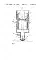
- FIG. 1the schematic longitudinal sectional view illustrates a laser beam device particularly suitable for melting and flame cutting.
- a focussing lens 2 in a lens mounting 3concentrates the incoming laser beam 1 at a focal spot 4 in the area of the surface of the workpiece 5 which, in the present case, is for example flat sheet metal.
- a housing 6there is arranged a sliding body, coaxial with the laser beam and consisting of an outer shell 7 and an inner shell 8, which is movable in the longitudinal direction of the laser beam 1 relative to the housing 6.
- a coolant channel 9for cooling the lens, through which channel flows a liquid or a gas type coolant 11 and which is fed via a coolant connection 10 whereby the latter can, at the same time, serve as a guiding connection piece in a corresponding slot in the housing 6.
- the coolant channel 9can be formed as a circular ring channel or it can consist of longitudinal axial grooves or slots, or else be formed in another manner. As the coolant 11, water is for preference used.
- an adjusting ring 12in the form of a threaded ring, the internal screw thread of which engages the mating outer screw thread of the outer shell 7.
- the shell assembly structure 7,8 and with it the focussing lens 2can be moved relative to one of the accepted reference points, parallel to the longitudinal axis of the laser beam 1, without the focussing lens being thereby tilted.
- a connection 14 for gas supply to the nozzle 13As the gas 15, according to the nature of the intended process, an inert gas (Ar, N 2 ) or a reactive gas (O 2 ) can be used.
- an inert gasAr, N 2
- a reactive gasO 2
- the connection 16is such that the coolant 17, for cooling the workpiece surface 5, will be fed concentrically towards the latter in the immediate proximity of the focal spot 4.
- connection 16can consist of several tubes lying on a conical envelope, or be formed as a cone-shaped ring channel whereby the tip of the virtual cone lies in the focal spot.
- coolant 17mainly a gas type or liquid is used, preferably water.
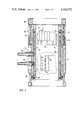
- FIG. 2shows a longitudinal section through a practical embodiment of the optical part of a laser beam cutting head, which contains the movable lens 2 from FIG. 1 (not shown here).
- the housingis made in two parts and consists of the actual housing 6 and the upper part of the housing 18, which are held together by six screws, not here shown (preferably hexagonal socket head screws, parallel to the optical axis).
- the components 6 and 18have for preference an internal circular section and an outer square section, but they can fundamentally have optionally polygonal or partly polygonal, partly circular or elliptical contact section. Generally, these components will be made from aluminum alloys, in order to save weight and reduce machining costs.
- the housing 6,for the purpose of a more rigid parallel construction of shells 7 and 8 and, at the same time for receiving the coolant connection 10 serving as a feed connection piece, is provided with a guide slot 31. Further, it has a right-angled cut-out 29 for a graduated scale 30, on which the relative position of the shells 7,8 can be read.
- the housing upper part 18has on opposite sides two diametrically opposed cut-outs 19 through which the adjusting ring 12 axially located in 18 can be turned by hand, for this purpose the ring having a knurled periphery. The relative position of the ring 12 can be read off on a scale 22 opposite a fixed mark in the housing 6.
- the adjusting ring 12has an internal thread 20, which the mating external screw thread 23 of the outer shell 7 engages.
- the latteris sealed relatively to the housing 6 by means of a sealing ring 24 (preferably an O-ring).
- a sealing ring 24preferably an O-ring
- the ring 12is made from brass (chromed) and the shell 7 from corrosion resistant steel.
- the outer shell 7is retained by an end ring 25 (Seeger ring).
- the fit between the housing 6 and the outer shell 7is such that the latter can be moved by hand, while well sealed, in the axial direction by means of the adjusting ring 12 (preferably H7).
- the inner shell 8which houses a sealing ring 26 (O-ring) has on its outer circumference the coolant channel 9, which in the present case is formed as a meandering slot 27, with straight portions lying on a gneratrix interconnected by arc-shaped portions disposed progressively around the circumference.
- This coolant channelcan also have other shapes, for example parallel slots or screw-shaped grooves.
- the inner shell 8is provided on its inner surface with a continuous inner thread 28 for the purpose of fixing the lens 2 with the lens mounting 3 (FIG. 1). This allows lenses of different focal lengths to be fitted, without having to adjust the incoming laser beam 1 (FIG. 1). Fine adjustment is achieved by means of the adjusting ring 12.
- the inner shell 8is likewise made of aluminium alloy.
- the construction shown hererefers to hollow cylindrical shells 7 and 8.
- This circular cross-sectionis not, however, the only practicable form and of course it can also be made from square, hexagonal, octagonal or other section (for example straight and circular arcs connected together) whereby, however, the engaging screw thread principle is retained at the respective places (20 and 23).
- FIG. 3shows a perspective view (turned over from the working position) of a nozzle assembly of a laser beam cutting head with four feed pipes for the workpiece coolant 17 (according to FIG. 1).
- a nozzle flange 32which supports the actual nozzle 13 with the nozzle opening 33 for the laser beam and the exhaust of the inert or reactive gas (refer to FIG. 1).
- the coolant connection 16 for cooling the workpiecesupplies the four feed pipes 34 for the coolant streams which lie on a virtual conical envelope, the apex of which is located in the focal spot (see FIG. 1). In this way the coolant streams are projected concentrically on to the surface of the workpiece in the immediate proximity of the focal spot 4.
- the arrangementcan be carried out with a different number of feed pipes 34 (for example 1, 2, 3, 6, 8, etc. ). The choice depends mainly on the laser performance and the thickness of the workpiece.
- FIG. 4a diagrammatic view is shown, partially in longitudinal section, of another construction of nozzle assembly with a conical nozzle.
- the nozzle 13is on the one hand connected rigidly and in a gas-tight manner in the housing 6 with nozzle flange 32, and on the other hand presents the nozzle orifice 33.
- the laser beam 1(see FIG. 1) not shown here, produces on the workpiece 5 the focal spot 4 shown in FIG. 1.
- Concentric with the nozzle axisa ring 35 for the coolant feed is arranged, into which the coolant connection 16 delivers.
- a toroidal-shaped circular channel 36 for the coolant 17(refer to FIG. 1) is formed. This extends in the direction towards the focal spot in a conical nozzle 37 to produce a cone-shaped coolant haze, which feeds concentrically on to the workpiece surface at the focal spot 4.
- FIG. 5shows a cross-section through the ring 35 of the cone nozzle 37 of FIG. 4.
- the remaining reference pointscorrespond to FIG. 4 and are self-explanatory.
- the vertical method of working illustratedis also valid for inclined use.
- the deviceis successfully used, for example, for drilling or finish-machining at angles of up to ⁇ 80° with respect to one of the aligned normal lines on the workpiece.
Landscapes
- Physics & Mathematics (AREA)
- Optics & Photonics (AREA)
- Engineering & Computer Science (AREA)
- Plasma & Fusion (AREA)
- Mechanical Engineering (AREA)
- Laser Beam Processing (AREA)
Abstract
Description
This invention relates to a process for laser beam melting and flame cutting and to a device therefor. It is particularly concerned with such a method and device wherein a laser beam is produced, guided and by means of a lens focussed and projected on to the surface of the workpiece to be treated, with an inert or reactive gas being fed coaxially of the laser beam to the focal spot so produced.
The machining of mainly laminar workpieces using laser beams is a continually growing branch of production technology for the profiling of metals, plastics and woods, etc. Thus, to a certain degree influenced by the well-known oxyacetylene gas welding and cutting technique, a laser beam guided by an optical system is focussed on to the surface of the workpiece and the material to be machined is locally heated in such a way that it melts, vaporises or is burnt. Usually, the focussing of the laser beam is accomplished with a concave mirror or a lens and, coaxially with the beam cone, a usually similarly cone-shaped nozzle is arranged to feed the inert or reactive gas on to the surface of the workpiece. The method and the device are known from different publications (for example, VDI-Z 199 (1977) No. 20 October, page 967 et seq).
An important prerequisite for trouble free operation with the laser beam process is, in one respect, the greatest possible freedom for the positioning of the focussing point with reference to the workpiece and, in another respect, the greatest possible reduction in the workpiece heating-up zone. These requirements are inadequately met with conventional devices.
One seeks to meet the first requirement by turning the lens for height adjustment, with a mounted threaded ring. As a result of the asymmetry of the lens and its mounting, as well as what is known in the trade as "play" in the lens mounting, the position of the axis of the laser beam is altered, and subsequent adjustment and setting up of the apparatus is unavoidable. Otherwise, as a result of incidence and reflection of the laser beam on the inner wall of the nozzle, the beam energy is partially dissipated and accurate focussing on to the surface of the workpiece is made impossible. The second requirement is, in the main, not met so that sharp-edged corners in the plan form of the workpiece cannot usually by executed accurately because of the localisation of heat.
The invention has for an object to provide a process as well as a device to make possible the movement of the focal point (focal spot) of the laser beam, relative to the surface of the workpiece, relative to the nozzle and relative to the supporting feet or the height scanner or another suitable reference point, in a simple manner, in the direction of the laser beam axis without readjustment with respect to the workpiece coordinates.
A further object of the invention is to indicate how the spread of the heating-up zone of the workpiece can be reduced, and especially how the localisation of heat at critical points can be avoided. This object is achieved in a process or device in accordance with the invention by employing the preferred features recited in theappendant claims
The invention will now be described in more detail with reference to the accompanying drawings, which are given by way of example. In the drawings:
FIG. 1 is a schematic longitudinal section through a laser beam device in accordance with the invention;
FIG. 2 is a longitudinal section through the optical part of a laser beam cutting head in accordance with the invention;
FIG. 3 is a perspective view of a nozzle assembly of the cutting head with four supply tubes for the workpiece coolant;
FIG. 4 is a diagrammatic and partial longitudinal cross-section through a nozzle assembly with a conical nozzle for the workpiece coolant; and
FIG. 5 is a cross-section through the cone nozzle ring of FIG. 4.
In FIG. 1 the schematic longitudinal sectional view illustrates a laser beam device particularly suitable for melting and flame cutting. A focussinglens 2 in a lens mounting 3 concentrates theincoming laser beam 1 at a focal spot 4 in the area of the surface of theworkpiece 5 which, in the present case, is for example flat sheet metal. In ahousing 6 there is arranged a sliding body, coaxial with the laser beam and consisting of anouter shell 7 and aninner shell 8, which is movable in the longitudinal direction of thelaser beam 1 relative to thehousing 6. In between the two tightly sealedshells coolant channel 9 for cooling the lens, through which channel flows a liquid or agas type coolant 11 and which is fed via acoolant connection 10 whereby the latter can, at the same time, serve as a guiding connection piece in a corresponding slot in thehousing 6. Thecoolant channel 9 can be formed as a circular ring channel or it can consist of longitudinal axial grooves or slots, or else be formed in another manner. As thecoolant 11, water is for preference used. In thehousing 6 there is located an adjustingring 12, in the form of a threaded ring, the internal screw thread of which engages the mating outer screw thread of theouter shell 7. By turning the adjustingring 12 theshell assembly structure lens 2 can be moved relative to one of the accepted reference points, parallel to the longitudinal axis of thelaser beam 1, without the focussing lens being thereby tilted. On a lower flange of thehousing 6 there is aconnection 14 for gas supply to thenozzle 13. As thegas 15, according to the nature of the intended process, an inert gas (Ar, N2) or a reactive gas (O2) can be used. On the lower part of anozzle 13 there is acoolant connection 16 for workpiece cooling. Theconnection 16 is such that thecoolant 17, for cooling theworkpiece surface 5, will be fed concentrically towards the latter in the immediate proximity of the focal spot 4. Accordingly, theconnection 16 can consist of several tubes lying on a conical envelope, or be formed as a cone-shaped ring channel whereby the tip of the virtual cone lies in the focal spot. As thecoolant 17, mainly a gas type or liquid is used, preferably water.
FIG. 2 shows a longitudinal section through a practical embodiment of the optical part of a laser beam cutting head, which contains themovable lens 2 from FIG. 1 (not shown here). The housing is made in two parts and consists of theactual housing 6 and the upper part of thehousing 18, which are held together by six screws, not here shown (preferably hexagonal socket head screws, parallel to the optical axis). Thecomponents housing 6, for the purpose of a more rigid parallel construction ofshells coolant connection 10 serving as a feed connection piece, is provided with aguide slot 31. Further, it has a right-angled cut-out 29 for a graduatedscale 30, on which the relative position of theshells upper part 18 has on opposite sides two diametrically opposed cut-outs 19 through which the adjustingring 12 axially located in 18 can be turned by hand, for this purpose the ring having a knurled periphery. The relative position of thering 12 can be read off on ascale 22 opposite a fixed mark in thehousing 6. The adjustingring 12 has aninternal thread 20, which the matingexternal screw thread 23 of theouter shell 7 engages. The latter is sealed relatively to thehousing 6 by means of a sealing ring 24 (preferably an O-ring). For preference thering 12 is made from brass (chromed) and theshell 7 from corrosion resistant steel. At the upper end theouter shell 7 is retained by an end ring 25 (Seeger ring). The fit between thehousing 6 and theouter shell 7 is such that the latter can be moved by hand, while well sealed, in the axial direction by means of the adjusting ring 12 (preferably H7). Theinner shell 8 which houses a sealing ring 26 (O-ring) has on its outer circumference thecoolant channel 9, which in the present case is formed as ameandering slot 27, with straight portions lying on a gneratrix interconnected by arc-shaped portions disposed progressively around the circumference. This coolant channel can also have other shapes, for example parallel slots or screw-shaped grooves. Theinner shell 8 is provided on its inner surface with a continuousinner thread 28 for the purpose of fixing thelens 2 with the lens mounting 3 (FIG. 1). This allows lenses of different focal lengths to be fitted, without having to adjust the incoming laser beam 1 (FIG. 1). Fine adjustment is achieved by means of the adjustingring 12. For preference theinner shell 8 is likewise made of aluminium alloy. The construction shown here refers to hollowcylindrical shells
FIG. 3 shows a perspective view (turned over from the working position) of a nozzle assembly of a laser beam cutting head with four feed pipes for the workpiece coolant 17 (according to FIG. 1). On thehousing 6 there sits anozzle flange 32, which supports theactual nozzle 13 with the nozzle opening 33 for the laser beam and the exhaust of the inert or reactive gas (refer to FIG. 1). Thecoolant connection 16 for cooling the workpiece supplies the fourfeed pipes 34 for the coolant streams which lie on a virtual conical envelope, the apex of which is located in the focal spot (see FIG. 1). In this way the coolant streams are projected concentrically on to the surface of the workpiece in the immediate proximity of the focal spot 4. Of course, the arrangement can be carried out with a different number of feed pipes 34 (for example 1, 2, 3, 6, 8, etc. ). The choice depends mainly on the laser performance and the thickness of the workpiece.
In FIG. 4 a diagrammatic view is shown, partially in longitudinal section, of another construction of nozzle assembly with a conical nozzle. Thenozzle 13 is on the one hand connected rigidly and in a gas-tight manner in thehousing 6 withnozzle flange 32, and on the other hand presents thenozzle orifice 33. The laser beam 1 (see FIG. 1) not shown here, produces on theworkpiece 5 the focal spot 4 shown in FIG. 1. Concentric with the nozzle axis aring 35 for the coolant feed is arranged, into which thecoolant connection 16 delivers. In the ring 35 a toroidal-shapedcircular channel 36 for the coolant 17 (refer to FIG. 1) is formed. This extends in the direction towards the focal spot in aconical nozzle 37 to produce a cone-shaped coolant haze, which feeds concentrically on to the workpiece surface at the focal spot 4.
FIG. 5 shows a cross-section through thering 35 of thecone nozzle 37 of FIG. 4. The remaining reference points correspond to FIG. 4 and are self-explanatory.
The vertical method of working illustrated is also valid for inclined use. In practice the device is successfully used, for example, for drilling or finish-machining at angles of up to ±80° with respect to one of the aligned normal lines on the workpiece.
Claims (6)
1. A laser beam device for melting and flame cutting, welding, sublimate cutting, drilling or marking, as well as finish-machining of materials, comprising a focussing lens for the laser beam and a nozzle for a gas feed, wherein the focussing lens is mounted in a swing-free manner for adjustment in the direction of the optical axis coaxial with the laser beam by means of an adjusting ring by which it is positively located on its longitudinal axis, the lens mounting comprising an adjustable shell structure in screw-threaded engagement with the adjusting ring and positioned with an accurate fit in a housing the internal section of which corresponds to the outer section of the shell, and wherein the adjustable shell and the housing are each of hollow cylindrical section and the shell has a continuous internal screw thread for the purpose of extracting a lens mount in which the lens is supported.
2. A laser beam device for melting and flame cutting, welding, sublimate cutting, drilling or marking, as well as finish-machining of materials, comprising a focussing lens for the laser beam and a nozzle for a gas feed, wherein the focussing lens is mounted in a swing-free manner for adjustment in the direction of the optical axis coaxial with the laser beam by means of an adjusting ring by which it is positively located on its longitudinal axis, the lens mounting comprising an adjustable shell structure in screw-threaded engagement with the adjusting ring and positioned with an accurate fit in a housing the internal section of which corresponds to the outer section of the shell, and wherein the shell structure comprises an inner shell and an outer shell between which are defined a coolant channel of meandering form comprising straight longitudinal grooves interconnected by arcuate grooves in the outer circumference of the inner shell and arranged in two axially spaced series for the circulation of a liquid or gaseous coolant for cooling the lens.
3. A laser beam device according to claim 2, wherein the adjusting ring is made from brass, the inner shell and the housing are made from aluminium alloy and the outer shell is made from a corrosion resistant steel, and wherein sealing rings are provided between the inner and outer shells and between the outer shell and the housing.
4. A laser beam device according to claim 1 or 2, wherein the nozzle is provided additionally with at least one tube for the supply feed of a coolant directed inwardly within a cone-shaped envelope towards the focal spot on to which the laser beam is focussed, the apex of the virtual cone defining the envelope lying approximately at the focal spot.
5. A laser beam device according to claim 1 or 2, wherein the nozzle is provided with a further nozzle connected to a circular ring channel between two conical surfaces coaxial with the laser beam, for the supply of a coolant.
6. The laser beam device according to claim 1 or 2, wherein said lens is independently adjustable along said longitudinal axis relative to said housing and nozzle.
Applications Claiming Priority (1)
| Application Number | Priority Date | Filing Date | Title |
|---|---|---|---|
| CH1038179ACH642891A5 (en) | 1979-11-21 | 1979-11-21 | METHOD AND DEVICE FOR PROCESSING A WORKPIECE BY LASER BEAM. |
Publications (1)
| Publication Number | Publication Date |
|---|---|
| US4324972Atrue US4324972A (en) | 1982-04-13 |
Family
ID=4362621
Family Applications (1)
| Application Number | Title | Priority Date | Filing Date |
|---|---|---|---|
| US06/207,926Expired - LifetimeUS4324972A (en) | 1979-11-21 | 1980-11-18 | Process and device for laser-beam melting and flame cutting |
Country Status (6)
| Country | Link |
|---|---|
| US (1) | US4324972A (en) |
| CH (1) | CH642891A5 (en) |
| DE (2) | DE8026897U1 (en) |
| FR (1) | FR2469975A1 (en) |
| GB (1) | GB2064399B (en) |
| IT (1) | IT1146065B (en) |
Cited By (63)
| Publication number | Priority date | Publication date | Assignee | Title |
|---|---|---|---|---|
| US4403134A (en)* | 1981-03-17 | 1983-09-06 | Trumpf Gmbh & Co. | Method and apparatus for cutting by means of a laser beam |
| US4417125A (en)* | 1981-02-24 | 1983-11-22 | Amada Engineering & Service Co., Inc. | Laser processing machine |
| US4494297A (en)* | 1981-10-06 | 1985-01-22 | Asea Aktiebolag | Method of producing castings with means to facilitate burr removal |
| US4639571A (en)* | 1985-11-29 | 1987-01-27 | The United States Of America As Represented By The United States Department Of Energy | Method of beam welding metallic parts together and apparatus for doing same |
| US4639572A (en)* | 1985-11-25 | 1987-01-27 | Ibm Corporation | Laser cutting of composite materials |
| DE3601504A1 (en)* | 1986-01-20 | 1987-07-23 | Arnold Glaswerke | Method of producing a hollow section for insulating glass |
| US4720621A (en)* | 1984-02-17 | 1988-01-19 | Robert Langen | Method and apparatus for removing impurities from metallic objects |
| US4723063A (en)* | 1985-04-16 | 1988-02-02 | Rofin-Sinar Laser Gmbh | Laser welding apparatus |
| US4798931A (en)* | 1987-07-17 | 1989-01-17 | Laser Applications, Inc. | Simultaneously cutting and welding sheet metal using laser energy |
| US4859826A (en)* | 1987-07-17 | 1989-08-22 | Laser Applications, Inc. | Simultaneously cutting and welding sheet metal using laser energy |
| AT391436B (en)* | 1987-10-30 | 1990-10-10 | Prihoda Hans | Laser cutting nozzle |
| US5113582A (en)* | 1990-11-13 | 1992-05-19 | General Electric Company | Method for making a gas turbine engine component |
| US5120395A (en)* | 1990-11-13 | 1992-06-09 | General Electric Company | Method for making a gas turbine engine component with a textured surface |
| US5210944A (en)* | 1990-11-13 | 1993-05-18 | General Electric Company | Method for making a gas turbine engine component |
| US5216808A (en)* | 1990-11-13 | 1993-06-08 | General Electric Company | Method for making or repairing a gas turbine engine component |
| US5227604A (en)* | 1991-06-28 | 1993-07-13 | Digital Equipment Corporation | Atmospheric pressure gaseous-flux-assisted laser reflow soldering |
| US5419971A (en)* | 1993-03-03 | 1995-05-30 | General Electric Company | Enhanced thermal barrier coating system |
| US5477025A (en)* | 1994-01-14 | 1995-12-19 | Quantum Laser Corporation | Laser nozzle |
| US5683600A (en)* | 1993-03-17 | 1997-11-04 | General Electric Company | Gas turbine engine component with compound cooling holes and method for making the same |
| US5702622A (en)* | 1995-04-28 | 1997-12-30 | Precitex Gmbh | Terminal head for processing a workpiece by means of a laser beam |
| EP0763627A3 (en)* | 1995-09-18 | 1998-04-29 | Voith Sulzer, Paper Technology North America, Inc. | Laser tail cutter assembly |
| US5994667A (en)* | 1997-10-15 | 1999-11-30 | Scimed Life Systems, Inc. | Method and apparatus for laser cutting hollow workpieces |
| US6124565A (en)* | 1998-04-13 | 2000-09-26 | Yamazaki Mazak Kabushiki Kaisha | Laser cutting machine |
| US6822187B1 (en)* | 1998-09-09 | 2004-11-23 | Gsi Lumonics Corporation | Robotically operated laser head |
| US20050150876A1 (en)* | 2003-12-18 | 2005-07-14 | Roberto Menin | Method and device for laser welding |
| US20060039419A1 (en)* | 2004-08-16 | 2006-02-23 | Tan Deshi | Method and apparatus for laser trimming of resistors using ultrafast laser pulse from ultrafast laser oscillator operating in picosecond and femtosecond pulse widths |
| US20060175307A1 (en)* | 2005-02-04 | 2006-08-10 | Honeywell International, Inc. | Hand-held laser welding wand with improved optical assembly serviceability features |
| US20070084839A1 (en)* | 2005-10-18 | 2007-04-19 | Wenwu Zhang | Thermal forming systems and active cooling processes |
| WO2008037310A1 (en)* | 2006-09-25 | 2008-04-03 | Keysystech Gmbh | Protective device for the optics of a laser working device with at least one nozzle arranged in a corner region |
| US20080219305A1 (en)* | 2005-10-05 | 2008-09-11 | Commissariat A L'energie | Method and Installation for Laser Cutting/Welding |
| US20090032505A1 (en)* | 2007-07-31 | 2009-02-05 | National Applied Research Laboratories | Cutting device for cutting hard-brittle material |
| US20120074110A1 (en)* | 2008-08-20 | 2012-03-29 | Zediker Mark S | Fluid laser jets, cutting heads, tools and methods of use |
| CN103212802A (en)* | 2012-01-19 | 2013-07-24 | 昆山思拓机器有限公司 | Coaxial type nozzle used for laser micro machining of thin-walled tube |
| CN103521921A (en)* | 2013-10-29 | 2014-01-22 | 西安炬光科技有限公司 | High-power semiconductor laser processing system |
| WO2015075152A1 (en)* | 2013-11-22 | 2015-05-28 | Salvagnini Italia S.P.A. | Laser cutting head for machine tool |
| US20150165559A1 (en)* | 2013-12-13 | 2015-06-18 | Jens Guenter Gaebelein | Methods and apparatus to perform a liquid-jet guided laser process and to simplify the maintenance thereof |
| US9089928B2 (en) | 2008-08-20 | 2015-07-28 | Foro Energy, Inc. | Laser systems and methods for the removal of structures |
| US20150352666A1 (en)* | 2013-02-27 | 2015-12-10 | Mitsubishi Heavy Industries, Ltd. | Machining device and machining method |
| CN105665705A (en)* | 2016-03-18 | 2016-06-15 | 山东能源重装集团大族再制造有限公司 | Metal 3D printing device |
| US20160167169A1 (en)* | 2009-11-03 | 2016-06-16 | The Secretary, Department Of Atomic Energy, Govt. Of India | Niobium based superconducting radio frequency(scrf) cavities comprising niobium components joined by laser welding, method and apparatus for manufacturing such cavities |
| US20170106471A1 (en)* | 2015-10-20 | 2017-04-20 | Disco Corporation | Laser processing apparatus |
| US20170120392A1 (en)* | 2015-10-30 | 2017-05-04 | Hypertherm, Inc. | Water Cooling of Laser Components |
| US9664012B2 (en) | 2008-08-20 | 2017-05-30 | Foro Energy, Inc. | High power laser decomissioning of multistring and damaged wells |
| WO2017088209A1 (en)* | 2015-11-24 | 2017-06-01 | 苏州大学张家港工业技术研究院 | Laser beam machining center |
| US9669492B2 (en) | 2008-08-20 | 2017-06-06 | Foro Energy, Inc. | High power laser offshore decommissioning tool, system and methods of use |
| US9731381B2 (en) | 2013-11-22 | 2017-08-15 | Salvagnini Italia S.P.A. | Laser cutting head for machine tool |
| CN107150171A (en)* | 2016-03-03 | 2017-09-12 | 通用电气公司 | Protective shields for liquid-guided laser cutting tools |
| US20180200833A1 (en)* | 2017-01-19 | 2018-07-19 | Fanuc Corporation | Laser machine |
| US20190009364A1 (en)* | 2016-12-15 | 2019-01-10 | John Murkin | Compact laser machining head |
| CN109202311A (en)* | 2018-11-08 | 2019-01-15 | 岗春激光科技(江苏)有限公司 | Laser condensing lens cylinder cooling device and laser process equipment |
| CN110549003A (en)* | 2018-05-30 | 2019-12-10 | 佛山市嘉实和生物科技有限公司 | laser equipment and laser cutting head equipment thereof |
| CN110899962A (en)* | 2019-12-19 | 2020-03-24 | 苏州德吉克激光设备有限公司 | Intelligent focusing device and method for optical fiber laser cutter |
| US10603745B2 (en) | 2015-05-04 | 2020-03-31 | Trumpf Werkzeugmaschinen Gmbh + Co. Kg | Cutting gas nozzle and laser cutting method having a displaceable sleeve for setting the flow characteristics |
| US20200198055A1 (en)* | 2018-12-19 | 2020-06-25 | Trumpf Werkzeugmaschinen Gmbh + Co. Kg | Beam-forming units with cooling systems for high-power lasers |
| US10799982B2 (en) | 2017-01-19 | 2020-10-13 | Fanuc Corporation | Nozzle for laser processing head |
| US11007603B2 (en)* | 2015-01-30 | 2021-05-18 | Makino Milling Machine Co., Ltd. | Laser beam machine and alignment adjusting method |
| CN113579410A (en)* | 2021-10-08 | 2021-11-02 | 振东冶金科技江苏有限公司 | Gas flame cutting device of self-adaptation dysmorphism work piece profile |
| US11298772B2 (en)* | 2018-09-26 | 2022-04-12 | Kabushiki Kaisha Toshiba | Welding apparatus and nozzle device |
| CN114535838A (en)* | 2022-04-02 | 2022-05-27 | 昆山恒盛金属科技有限公司 | Laser cutting device for sheet metal processing |
| US11465238B2 (en)* | 2019-02-13 | 2022-10-11 | Bystronic Laser Ag | Gas guide, laser cutting head and laser cutting machine |
| US11590606B2 (en)* | 2008-08-20 | 2023-02-28 | Foro Energy, Inc. | High power laser tunneling mining and construction equipment and methods of use |
| JP2024103673A (en)* | 2020-01-07 | 2024-08-01 | 株式会社東京精密 | Condenser lens unit and laser processing device |
| WO2024188656A1 (en)* | 2023-03-14 | 2024-09-19 | Trotec Laser Gmbh | Protective funnel for a laser device and method therefor |
Families Citing this family (23)
| Publication number | Priority date | Publication date | Assignee | Title |
|---|---|---|---|---|
| SU1266463A3 (en)* | 1981-07-10 | 1986-10-23 | Хауни-Верке Кербер Унд Ко.,Кг (Фирма) | Device for punching moving thin material |
| DE3332531A1 (en)* | 1983-09-09 | 1985-03-28 | Hans-Dieter 7121 Gemmrigheim Layh | Laser system for machining workpieces |
| DE3411140A1 (en)* | 1984-03-26 | 1985-09-26 | BIAS Forschungs- und Entwicklungs-Labor für angewandte Strahltechnik GmbH, 2820 Bremen | Process for aligning a working head for a focused high-output energy source, and a working head, in particular for executing the process |
| DE3433961A1 (en)* | 1984-05-18 | 1985-11-21 | M.A.N. Maschinenfabrik Augsburg-Nürnberg AG, 8000 München | METHOD FOR SUPPORTING AN ICEBREAKING PROCESS |
| GB2163692B (en)* | 1984-08-30 | 1988-11-30 | Ferranti Plc | Laser apparatus |
| CH667413A5 (en)* | 1985-09-24 | 1988-10-14 | Laser Work Ag | METHOD AND DEVICE FOR FOCUSING A LENS IN THE LASER BEAM PROCESSING OF A WORKPIECE. |
| AT393241B (en)* | 1986-06-11 | 1991-09-10 | Aga Ab | Method for the laser cutting of metallic workpieces |
| US4952771A (en)* | 1986-12-18 | 1990-08-28 | Aesculap Ag | Process for cutting a material by means of a laser beam |
| CH682060A5 (en)* | 1987-05-18 | 1993-07-15 | Weidmueller C A Gmbh Co | |
| JPH0324251Y2 (en)* | 1987-09-03 | 1991-05-27 | ||
| DE3801068A1 (en)* | 1988-01-15 | 1989-07-27 | Maho Ag | Method and apparatus for stock removal by means of bundled energy beams |
| DE3940766A1 (en)* | 1989-12-09 | 1991-06-13 | Messer Griesheim Gmbh | METHOD FOR CUTTING MATERIALS |
| AT401247B (en)* | 1991-02-15 | 1996-07-25 | Schuoecker Dieter Dipl Ing Dr | Laser-machining apparatus |
| DE4240189A1 (en)* | 1992-11-30 | 1994-06-01 | Linde Ag | Process for welding workpieces using a laser beam and laser welding nozzle |
| DE4240190A1 (en)* | 1992-11-30 | 1994-06-01 | Linde Ag | Process for the machining of a workpiece by means of a laser beam and laser nozzle |
| DE19537924C2 (en)* | 1994-10-18 | 1997-06-12 | Thyssen Industrie | Method for cooling the weld seam area during laser welding and device for carrying out this method |
| RU2172233C2 (en)* | 1999-06-29 | 2001-08-20 | Жулев Юрий Григорьевич | Method and apparatus for cutting materials by laser beam |
| EP1459835B1 (en) | 2003-03-15 | 2013-04-24 | TRUMPF Werkzeugmaschinen GmbH + Co. KG | Laser machining method with a laser machining nozzle for laser welding and laser cutting |
| DE102005030067A1 (en) | 2005-06-27 | 2006-12-28 | FHS Hochschule für Technik, Wirtschaft und soziale Arbeit St. Gallen | Apparatus for producing objects using generative method, e.g. selective laser sintering, has system for generating mist of fluid between electromagnetic component and process chamber |
| GB0610305D0 (en)* | 2006-05-24 | 2006-07-05 | Boc Group Plc | Laser cutting head |
| CN102513703B (en)* | 2011-11-22 | 2014-11-26 | 无锡庆源激光科技有限公司 | Laser cutting air blowing spray head |
| CN113118650B (en)* | 2019-12-31 | 2022-03-15 | 江苏亚威机床股份有限公司 | Thick plate laser perforation processing method |
| CN116532789A (en)* | 2023-06-08 | 2023-08-04 | 苏州德龙激光股份有限公司 | A laser cutting head |
Citations (5)
| Publication number | Priority date | Publication date | Assignee | Title |
|---|---|---|---|---|
| US3569660A (en)* | 1968-07-29 | 1971-03-09 | Nat Res Dev | Laser cutting apparatus |
| US3626141A (en)* | 1970-04-30 | 1971-12-07 | Quantronix Corp | Laser scribing apparatus |
| US3679863A (en)* | 1968-11-12 | 1972-07-25 | Nat Res Dev | Thermal cutting apparatus |
| US4027137A (en)* | 1975-09-17 | 1977-05-31 | International Business Machines Corporation | Laser drilling nozzle |
| JPS54131543A (en)* | 1978-04-04 | 1979-10-12 | Kawasaki Steel Co | Laser welding nozzle |
Family Cites Families (8)
| Publication number | Priority date | Publication date | Assignee | Title |
|---|---|---|---|---|
| US3246563A (en)* | 1962-09-26 | 1966-04-19 | Milton L Quammen | Telescopic eyepiece assembly with static and dynamic bellows-type seal |
| DE1615392A1 (en)* | 1967-03-28 | 1970-05-21 | Siemens Ag | Optical device for processing laser |
| CA991277A (en)* | 1972-07-03 | 1976-06-15 | David Sciaky | Laser beam manipulator and protective system |
| DE2338514A1 (en)* | 1973-07-30 | 1975-02-20 | Lks Laser Kombinationssysteme | Laser-beam machining using oxygen - with concentric water-cooling jets on both sides of the part being machined |
| JPS5549721B2 (en)* | 1973-07-30 | 1980-12-13 | ||
| US4002877A (en)* | 1974-12-13 | 1977-01-11 | United Technologies Corporation | Method of cutting with laser radiation and liquid coolant |
| DD123788A1 (en)* | 1976-01-09 | 1977-01-19 | ||
| US4125757A (en)* | 1977-11-04 | 1978-11-14 | The Torrington Company | Apparatus and method for laser cutting |
- 1979
- 1979-11-21CHCH1038179Apatent/CH642891A5/ennot_activeIP Right Cessation
- 1980
- 1980-10-08DEDE8026897Upatent/DE8026897U1/ennot_activeExpired
- 1980-10-08DEDE19803037981patent/DE3037981A1/enactiveGranted
- 1980-11-17FRFR8024382Apatent/FR2469975A1/enactiveGranted
- 1980-11-17GBGB8036797Apatent/GB2064399B/ennot_activeExpired
- 1980-11-18USUS06/207,926patent/US4324972A/ennot_activeExpired - Lifetime
- 1980-11-19ITIT50198/80Apatent/IT1146065B/enactive
Patent Citations (5)
| Publication number | Priority date | Publication date | Assignee | Title |
|---|---|---|---|---|
| US3569660A (en)* | 1968-07-29 | 1971-03-09 | Nat Res Dev | Laser cutting apparatus |
| US3679863A (en)* | 1968-11-12 | 1972-07-25 | Nat Res Dev | Thermal cutting apparatus |
| US3626141A (en)* | 1970-04-30 | 1971-12-07 | Quantronix Corp | Laser scribing apparatus |
| US4027137A (en)* | 1975-09-17 | 1977-05-31 | International Business Machines Corporation | Laser drilling nozzle |
| JPS54131543A (en)* | 1978-04-04 | 1979-10-12 | Kawasaki Steel Co | Laser welding nozzle |
Cited By (81)
| Publication number | Priority date | Publication date | Assignee | Title |
|---|---|---|---|---|
| US4417125A (en)* | 1981-02-24 | 1983-11-22 | Amada Engineering & Service Co., Inc. | Laser processing machine |
| US4403134A (en)* | 1981-03-17 | 1983-09-06 | Trumpf Gmbh & Co. | Method and apparatus for cutting by means of a laser beam |
| US4494297A (en)* | 1981-10-06 | 1985-01-22 | Asea Aktiebolag | Method of producing castings with means to facilitate burr removal |
| US4720621A (en)* | 1984-02-17 | 1988-01-19 | Robert Langen | Method and apparatus for removing impurities from metallic objects |
| US4723063A (en)* | 1985-04-16 | 1988-02-02 | Rofin-Sinar Laser Gmbh | Laser welding apparatus |
| US4639572A (en)* | 1985-11-25 | 1987-01-27 | Ibm Corporation | Laser cutting of composite materials |
| US4639571A (en)* | 1985-11-29 | 1987-01-27 | The United States Of America As Represented By The United States Department Of Energy | Method of beam welding metallic parts together and apparatus for doing same |
| DE3601504A1 (en)* | 1986-01-20 | 1987-07-23 | Arnold Glaswerke | Method of producing a hollow section for insulating glass |
| US4798931A (en)* | 1987-07-17 | 1989-01-17 | Laser Applications, Inc. | Simultaneously cutting and welding sheet metal using laser energy |
| US4859826A (en)* | 1987-07-17 | 1989-08-22 | Laser Applications, Inc. | Simultaneously cutting and welding sheet metal using laser energy |
| AT391436B (en)* | 1987-10-30 | 1990-10-10 | Prihoda Hans | Laser cutting nozzle |
| US5113582A (en)* | 1990-11-13 | 1992-05-19 | General Electric Company | Method for making a gas turbine engine component |
| US5120395A (en)* | 1990-11-13 | 1992-06-09 | General Electric Company | Method for making a gas turbine engine component with a textured surface |
| US5210944A (en)* | 1990-11-13 | 1993-05-18 | General Electric Company | Method for making a gas turbine engine component |
| US5216808A (en)* | 1990-11-13 | 1993-06-08 | General Electric Company | Method for making or repairing a gas turbine engine component |
| US5227604A (en)* | 1991-06-28 | 1993-07-13 | Digital Equipment Corporation | Atmospheric pressure gaseous-flux-assisted laser reflow soldering |
| US5419971A (en)* | 1993-03-03 | 1995-05-30 | General Electric Company | Enhanced thermal barrier coating system |
| US6503574B1 (en) | 1993-03-03 | 2003-01-07 | General Electric Co. | Method for producing an enhanced thermal barrier coating system |
| US5683600A (en)* | 1993-03-17 | 1997-11-04 | General Electric Company | Gas turbine engine component with compound cooling holes and method for making the same |
| US5477025A (en)* | 1994-01-14 | 1995-12-19 | Quantum Laser Corporation | Laser nozzle |
| US5702622A (en)* | 1995-04-28 | 1997-12-30 | Precitex Gmbh | Terminal head for processing a workpiece by means of a laser beam |
| EP0763627A3 (en)* | 1995-09-18 | 1998-04-29 | Voith Sulzer, Paper Technology North America, Inc. | Laser tail cutter assembly |
| US5994667A (en)* | 1997-10-15 | 1999-11-30 | Scimed Life Systems, Inc. | Method and apparatus for laser cutting hollow workpieces |
| US6124565A (en)* | 1998-04-13 | 2000-09-26 | Yamazaki Mazak Kabushiki Kaisha | Laser cutting machine |
| US6822187B1 (en)* | 1998-09-09 | 2004-11-23 | Gsi Lumonics Corporation | Robotically operated laser head |
| US20050150876A1 (en)* | 2003-12-18 | 2005-07-14 | Roberto Menin | Method and device for laser welding |
| US7786404B2 (en)* | 2003-12-18 | 2010-08-31 | Comau S.P.A. | Method and device for laser welding |
| US20060039419A1 (en)* | 2004-08-16 | 2006-02-23 | Tan Deshi | Method and apparatus for laser trimming of resistors using ultrafast laser pulse from ultrafast laser oscillator operating in picosecond and femtosecond pulse widths |
| US20060175307A1 (en)* | 2005-02-04 | 2006-08-10 | Honeywell International, Inc. | Hand-held laser welding wand with improved optical assembly serviceability features |
| US7550693B2 (en)* | 2005-02-04 | 2009-06-23 | Honeywell International Inc. | Hand-held laser welding wand with improved optical assembly serviceability features |
| US20080219305A1 (en)* | 2005-10-05 | 2008-09-11 | Commissariat A L'energie | Method and Installation for Laser Cutting/Welding |
| US8153928B2 (en)* | 2005-10-05 | 2012-04-10 | Commissariat A L'energie Atomique | Method and installation for laser cutting/welding |
| US20070084839A1 (en)* | 2005-10-18 | 2007-04-19 | Wenwu Zhang | Thermal forming systems and active cooling processes |
| WO2008037310A1 (en)* | 2006-09-25 | 2008-04-03 | Keysystech Gmbh | Protective device for the optics of a laser working device with at least one nozzle arranged in a corner region |
| US7919724B2 (en)* | 2007-07-31 | 2011-04-05 | National Applied Research Laboratories | Cutting device for cutting hard-brittle material |
| US20090032505A1 (en)* | 2007-07-31 | 2009-02-05 | National Applied Research Laboratories | Cutting device for cutting hard-brittle material |
| US20120074110A1 (en)* | 2008-08-20 | 2012-03-29 | Zediker Mark S | Fluid laser jets, cutting heads, tools and methods of use |
| US9664012B2 (en) | 2008-08-20 | 2017-05-30 | Foro Energy, Inc. | High power laser decomissioning of multistring and damaged wells |
| US11590606B2 (en)* | 2008-08-20 | 2023-02-28 | Foro Energy, Inc. | High power laser tunneling mining and construction equipment and methods of use |
| US9089928B2 (en) | 2008-08-20 | 2015-07-28 | Foro Energy, Inc. | Laser systems and methods for the removal of structures |
| US9669492B2 (en) | 2008-08-20 | 2017-06-06 | Foro Energy, Inc. | High power laser offshore decommissioning tool, system and methods of use |
| US20160167169A1 (en)* | 2009-11-03 | 2016-06-16 | The Secretary, Department Of Atomic Energy, Govt. Of India | Niobium based superconducting radio frequency(scrf) cavities comprising niobium components joined by laser welding, method and apparatus for manufacturing such cavities |
| CN103212802A (en)* | 2012-01-19 | 2013-07-24 | 昆山思拓机器有限公司 | Coaxial type nozzle used for laser micro machining of thin-walled tube |
| US20150352666A1 (en)* | 2013-02-27 | 2015-12-10 | Mitsubishi Heavy Industries, Ltd. | Machining device and machining method |
| US9757816B2 (en)* | 2013-02-27 | 2017-09-12 | Mitsubishi Heavy Industries, Ltd. | Machining device and machining method |
| CN103521921A (en)* | 2013-10-29 | 2014-01-22 | 西安炬光科技有限公司 | High-power semiconductor laser processing system |
| WO2015075152A1 (en)* | 2013-11-22 | 2015-05-28 | Salvagnini Italia S.P.A. | Laser cutting head for machine tool |
| US9731381B2 (en) | 2013-11-22 | 2017-08-15 | Salvagnini Italia S.P.A. | Laser cutting head for machine tool |
| RU2653892C2 (en)* | 2013-11-22 | 2018-05-15 | Сальваньини Италия С.П.А. | Laser cutting head for machine tool |
| US10173285B2 (en) | 2013-11-22 | 2019-01-08 | Salvagnini Italia S.P.A. | Laser cutting head for machine tool |
| US20150165559A1 (en)* | 2013-12-13 | 2015-06-18 | Jens Guenter Gaebelein | Methods and apparatus to perform a liquid-jet guided laser process and to simplify the maintenance thereof |
| US10940561B2 (en)* | 2013-12-13 | 2021-03-09 | Avonisys Ag | Methods and apparatus to perform a liquid-jet guided laser process and to simplify the maintenance thereof |
| US10022820B2 (en)* | 2013-12-13 | 2018-07-17 | Avonisys Ag | Methods and apparatus to perform a liquid-jet guided laser process and to simplify the maintenance thereof |
| US20180318959A1 (en)* | 2013-12-13 | 2018-11-08 | Avonisys Ag | Methods and apparatus to perform a liquid-jet guided laser process and to simplify the maintenance thereof |
| US11007603B2 (en)* | 2015-01-30 | 2021-05-18 | Makino Milling Machine Co., Ltd. | Laser beam machine and alignment adjusting method |
| US10603745B2 (en) | 2015-05-04 | 2020-03-31 | Trumpf Werkzeugmaschinen Gmbh + Co. Kg | Cutting gas nozzle and laser cutting method having a displaceable sleeve for setting the flow characteristics |
| US10751836B2 (en) | 2015-05-04 | 2020-08-25 | Trumpf Werkzeugmaschinen Gmbh + Co. Kg | Gas nozzle having a displaceable valve sleeve |
| US11135675B2 (en) | 2015-05-04 | 2021-10-05 | Trumpf Werkzeugmaschinen Gmbh + Co. Kg | Gas nozzle having a displaceable valve sleeve |
| US20170106471A1 (en)* | 2015-10-20 | 2017-04-20 | Disco Corporation | Laser processing apparatus |
| US20170120392A1 (en)* | 2015-10-30 | 2017-05-04 | Hypertherm, Inc. | Water Cooling of Laser Components |
| US10525554B2 (en)* | 2015-10-30 | 2020-01-07 | Hypertherm, Inc. | Water cooling of laser components |
| WO2017088209A1 (en)* | 2015-11-24 | 2017-06-01 | 苏州大学张家港工业技术研究院 | Laser beam machining center |
| CN107150171A (en)* | 2016-03-03 | 2017-09-12 | 通用电气公司 | Protective shields for liquid-guided laser cutting tools |
| CN105665705A (en)* | 2016-03-18 | 2016-06-15 | 山东能源重装集团大族再制造有限公司 | Metal 3D printing device |
| US20190009364A1 (en)* | 2016-12-15 | 2019-01-10 | John Murkin | Compact laser machining head |
| US10814425B2 (en)* | 2016-12-15 | 2020-10-27 | John Murkin | Compact laser machining head |
| US20180200833A1 (en)* | 2017-01-19 | 2018-07-19 | Fanuc Corporation | Laser machine |
| US10562131B2 (en)* | 2017-01-19 | 2020-02-18 | Fanuc Corporation | Laser machine |
| US10799982B2 (en) | 2017-01-19 | 2020-10-13 | Fanuc Corporation | Nozzle for laser processing head |
| CN110549003A (en)* | 2018-05-30 | 2019-12-10 | 佛山市嘉实和生物科技有限公司 | laser equipment and laser cutting head equipment thereof |
| US11298772B2 (en)* | 2018-09-26 | 2022-04-12 | Kabushiki Kaisha Toshiba | Welding apparatus and nozzle device |
| CN109202311A (en)* | 2018-11-08 | 2019-01-15 | 岗春激光科技(江苏)有限公司 | Laser condensing lens cylinder cooling device and laser process equipment |
| US20200198055A1 (en)* | 2018-12-19 | 2020-06-25 | Trumpf Werkzeugmaschinen Gmbh + Co. Kg | Beam-forming units with cooling systems for high-power lasers |
| US11679448B2 (en)* | 2018-12-19 | 2023-06-20 | TRUMPF Werkzeugmaschinen SE + Co. KG | Beam-forming units with cooling systems for high-power lasers |
| US11465238B2 (en)* | 2019-02-13 | 2022-10-11 | Bystronic Laser Ag | Gas guide, laser cutting head and laser cutting machine |
| CN110899962A (en)* | 2019-12-19 | 2020-03-24 | 苏州德吉克激光设备有限公司 | Intelligent focusing device and method for optical fiber laser cutter |
| JP2024103673A (en)* | 2020-01-07 | 2024-08-01 | 株式会社東京精密 | Condenser lens unit and laser processing device |
| CN113579410B (en)* | 2021-10-08 | 2021-12-07 | 振东冶金科技江苏有限公司 | Gas flame cutting device of self-adaptation dysmorphism work piece profile |
| CN113579410A (en)* | 2021-10-08 | 2021-11-02 | 振东冶金科技江苏有限公司 | Gas flame cutting device of self-adaptation dysmorphism work piece profile |
| CN114535838A (en)* | 2022-04-02 | 2022-05-27 | 昆山恒盛金属科技有限公司 | Laser cutting device for sheet metal processing |
| WO2024188656A1 (en)* | 2023-03-14 | 2024-09-19 | Trotec Laser Gmbh | Protective funnel for a laser device and method therefor |
Also Published As
| Publication number | Publication date |
|---|---|
| IT1146065B (en) | 1986-11-12 |
| FR2469975B1 (en) | 1984-09-28 |
| DE3037981C2 (en) | 1988-10-13 |
| DE8026897U1 (en) | 1981-09-17 |
| IT8050198A0 (en) | 1980-11-19 |
| DE3037981A1 (en) | 1981-06-04 |
| CH642891A5 (en) | 1984-05-15 |
| FR2469975A1 (en) | 1981-05-29 |
| GB2064399B (en) | 1984-10-03 |
| GB2064399A (en) | 1981-06-17 |
Similar Documents
| Publication | Publication Date | Title |
|---|---|---|
| US4324972A (en) | Process and device for laser-beam melting and flame cutting | |
| US6608281B2 (en) | Laser beam machining head and laser beam machining apparatus having same | |
| CA2040166C (en) | Apparatus and method for automatically aligning a welding device for butt welding workpieces | |
| US9102009B2 (en) | Method and apparatus for laser welding with mixed gas plasma suppression | |
| RU2750313C2 (en) | Method for laser processing of metal material with a high level of dynamic control of the axes of movement of the laser beam along a pre-selected processing path, as well as a machine and a computer program for implementing this method | |
| GB2071401A (en) | Laser beam reflection system | |
| CN114523207B (en) | Laser welding method | |
| US3972599A (en) | Method and apparatus for focussing laser beams | |
| CN102059455A (en) | Laser double-side synchronous welding system with skin-skeleton structure | |
| CN111940905A (en) | Coaxial dual-focus laser filler wire welding method for two sides of thin-plate titanium alloy T-shaped joint | |
| JPH11333584A (en) | Laser beam machining head | |
| US4572942A (en) | Gas-metal-arc welding process | |
| US20190009365A1 (en) | Gas delivery system | |
| US5011253A (en) | Optical system for laser marking | |
| CN109877451A (en) | A handheld laser welding gun | |
| JPH04294888A (en) | Laser beam machining method and machining head used for said method | |
| RU2120365C1 (en) | Method of and device for making of pipes by laser welding of longitudinal seams | |
| ES2437587T3 (en) | Welding device for tubes from a metal grooved tube | |
| CN115074722A (en) | Handheld laser cladding head device | |
| JPH10216978A (en) | Laser beam machining head | |
| US20040094526A1 (en) | Cutting laser beam nozzle assembly | |
| US10835995B2 (en) | Integrated feeder nozzle | |
| CN207016855U (en) | Laser cladding apparatus | |
| CN214602503U (en) | Adjustable welding head of handheld facula of laser | |
| JPS5691992A (en) | Laser welding method and laser working head |
Legal Events
| Date | Code | Title | Description |
|---|---|---|---|
| STCF | Information on status: patent grant | Free format text:PATENTED CASE |