US4324572A - Soot filter for an exhaust arrangement of an internal combustion engine - Google Patents
Soot filter for an exhaust arrangement of an internal combustion engineDownload PDFInfo
- Publication number
- US4324572A US4324572AUS06/237,899US23789981AUS4324572AUS 4324572 AUS4324572 AUS 4324572AUS 23789981 AUS23789981 AUS 23789981AUS 4324572 AUS4324572 AUS 4324572A
- Authority
- US
- United States
- Prior art keywords
- filter arrangement
- arrangement according
- thread
- filter
- housing
- Prior art date
- Legal status (The legal status is an assumption and is not a legal conclusion. Google has not performed a legal analysis and makes no representation as to the accuracy of the status listed.)
- Expired - Lifetime
Links
Images

Classifications
- F—MECHANICAL ENGINEERING; LIGHTING; HEATING; WEAPONS; BLASTING
- F01—MACHINES OR ENGINES IN GENERAL; ENGINE PLANTS IN GENERAL; STEAM ENGINES
- F01N—GAS-FLOW SILENCERS OR EXHAUST APPARATUS FOR MACHINES OR ENGINES IN GENERAL; GAS-FLOW SILENCERS OR EXHAUST APPARATUS FOR INTERNAL-COMBUSTION ENGINES
- F01N13/00—Exhaust or silencing apparatus characterised by constructional features
- F01N13/18—Construction facilitating manufacture, assembly, or disassembly
- F01N13/1805—Fixing exhaust manifolds, exhaust pipes or pipe sections to each other, to engine or to vehicle body
- F01N13/1811—Fixing exhaust manifolds, exhaust pipes or pipe sections to each other, to engine or to vehicle body with means permitting relative movement, e.g. compensation of thermal expansion or vibration
- F—MECHANICAL ENGINEERING; LIGHTING; HEATING; WEAPONS; BLASTING
- F01—MACHINES OR ENGINES IN GENERAL; ENGINE PLANTS IN GENERAL; STEAM ENGINES
- F01N—GAS-FLOW SILENCERS OR EXHAUST APPARATUS FOR MACHINES OR ENGINES IN GENERAL; GAS-FLOW SILENCERS OR EXHAUST APPARATUS FOR INTERNAL-COMBUSTION ENGINES
- F01N3/00—Exhaust or silencing apparatus having means for purifying, rendering innocuous, or otherwise treating exhaust
- F01N3/02—Exhaust or silencing apparatus having means for purifying, rendering innocuous, or otherwise treating exhaust for cooling, or for removing solid constituents of, exhaust
- F01N3/021—Exhaust or silencing apparatus having means for purifying, rendering innocuous, or otherwise treating exhaust for cooling, or for removing solid constituents of, exhaust by means of filters
- F01N3/0212—Exhaust or silencing apparatus having means for purifying, rendering innocuous, or otherwise treating exhaust for cooling, or for removing solid constituents of, exhaust by means of filters with one or more perforated tubes surrounded by filtering material, e.g. filter candles
- F—MECHANICAL ENGINEERING; LIGHTING; HEATING; WEAPONS; BLASTING
- F01—MACHINES OR ENGINES IN GENERAL; ENGINE PLANTS IN GENERAL; STEAM ENGINES
- F01N—GAS-FLOW SILENCERS OR EXHAUST APPARATUS FOR MACHINES OR ENGINES IN GENERAL; GAS-FLOW SILENCERS OR EXHAUST APPARATUS FOR INTERNAL-COMBUSTION ENGINES
- F01N2260/00—Exhaust treating devices having provisions not otherwise provided for
- F01N2260/10—Exhaust treating devices having provisions not otherwise provided for for avoiding stress caused by expansions or contractions due to temperature variations
- F—MECHANICAL ENGINEERING; LIGHTING; HEATING; WEAPONS; BLASTING
- F01—MACHINES OR ENGINES IN GENERAL; ENGINE PLANTS IN GENERAL; STEAM ENGINES
- F01N—GAS-FLOW SILENCERS OR EXHAUST APPARATUS FOR MACHINES OR ENGINES IN GENERAL; GAS-FLOW SILENCERS OR EXHAUST APPARATUS FOR INTERNAL-COMBUSTION ENGINES
- F01N2330/00—Structure of catalyst support or particle filter
- F01N2330/10—Fibrous material, e.g. mineral or metallic wool
- F—MECHANICAL ENGINEERING; LIGHTING; HEATING; WEAPONS; BLASTING
- F01—MACHINES OR ENGINES IN GENERAL; ENGINE PLANTS IN GENERAL; STEAM ENGINES
- F01N—GAS-FLOW SILENCERS OR EXHAUST APPARATUS FOR MACHINES OR ENGINES IN GENERAL; GAS-FLOW SILENCERS OR EXHAUST APPARATUS FOR INTERNAL-COMBUSTION ENGINES
- F01N2450/00—Methods or apparatus for fitting, inserting or repairing different elements
- F01N2450/24—Methods or apparatus for fitting, inserting or repairing different elements by bolts, screws, rivets or the like
- F—MECHANICAL ENGINEERING; LIGHTING; HEATING; WEAPONS; BLASTING
- F01—MACHINES OR ENGINES IN GENERAL; ENGINE PLANTS IN GENERAL; STEAM ENGINES
- F01N—GAS-FLOW SILENCERS OR EXHAUST APPARATUS FOR MACHINES OR ENGINES IN GENERAL; GAS-FLOW SILENCERS OR EXHAUST APPARATUS FOR INTERNAL-COMBUSTION ENGINES
- F01N2470/00—Structure or shape of exhaust gas passages, pipes or tubes
- F01N2470/02—Tubes being perforated
- F—MECHANICAL ENGINEERING; LIGHTING; HEATING; WEAPONS; BLASTING
- F01—MACHINES OR ENGINES IN GENERAL; ENGINE PLANTS IN GENERAL; STEAM ENGINES
- F01N—GAS-FLOW SILENCERS OR EXHAUST APPARATUS FOR MACHINES OR ENGINES IN GENERAL; GAS-FLOW SILENCERS OR EXHAUST APPARATUS FOR INTERNAL-COMBUSTION ENGINES
- F01N2470/00—Structure or shape of exhaust gas passages, pipes or tubes
- F01N2470/12—Tubes being corrugated
- F—MECHANICAL ENGINEERING; LIGHTING; HEATING; WEAPONS; BLASTING
- F01—MACHINES OR ENGINES IN GENERAL; ENGINE PLANTS IN GENERAL; STEAM ENGINES
- F01N—GAS-FLOW SILENCERS OR EXHAUST APPARATUS FOR MACHINES OR ENGINES IN GENERAL; GAS-FLOW SILENCERS OR EXHAUST APPARATUS FOR INTERNAL-COMBUSTION ENGINES
- F01N2470/00—Structure or shape of exhaust gas passages, pipes or tubes
- F01N2470/16—Plurality of inlet tubes, e.g. discharging into different chambers
- F—MECHANICAL ENGINEERING; LIGHTING; HEATING; WEAPONS; BLASTING
- F01—MACHINES OR ENGINES IN GENERAL; ENGINE PLANTS IN GENERAL; STEAM ENGINES
- F01N—GAS-FLOW SILENCERS OR EXHAUST APPARATUS FOR MACHINES OR ENGINES IN GENERAL; GAS-FLOW SILENCERS OR EXHAUST APPARATUS FOR INTERNAL-COMBUSTION ENGINES
- F01N2470/00—Structure or shape of exhaust gas passages, pipes or tubes
- F01N2470/18—Structure or shape of exhaust gas passages, pipes or tubes the axis of inlet or outlet tubes being other than the longitudinal axis of apparatus
- Y—GENERAL TAGGING OF NEW TECHNOLOGICAL DEVELOPMENTS; GENERAL TAGGING OF CROSS-SECTIONAL TECHNOLOGIES SPANNING OVER SEVERAL SECTIONS OF THE IPC; TECHNICAL SUBJECTS COVERED BY FORMER USPC CROSS-REFERENCE ART COLLECTIONS [XRACs] AND DIGESTS
- Y02—TECHNOLOGIES OR APPLICATIONS FOR MITIGATION OR ADAPTATION AGAINST CLIMATE CHANGE
- Y02T—CLIMATE CHANGE MITIGATION TECHNOLOGIES RELATED TO TRANSPORTATION
- Y02T10/00—Road transport of goods or passengers
- Y02T10/10—Internal combustion engine [ICE] based vehicles
- Y02T10/12—Improving ICE efficiencies
- Y—GENERAL TAGGING OF NEW TECHNOLOGICAL DEVELOPMENTS; GENERAL TAGGING OF CROSS-SECTIONAL TECHNOLOGIES SPANNING OVER SEVERAL SECTIONS OF THE IPC; TECHNICAL SUBJECTS COVERED BY FORMER USPC CROSS-REFERENCE ART COLLECTIONS [XRACs] AND DIGESTS
- Y10—TECHNICAL SUBJECTS COVERED BY FORMER USPC
- Y10S—TECHNICAL SUBJECTS COVERED BY FORMER USPC CROSS-REFERENCE ART COLLECTIONS [XRACs] AND DIGESTS
- Y10S55/00—Gas separation
- Y10S55/30—Exhaust treatment
Definitions
- the present inventionrelates to a filter and, more particularly, to a soot filter adapted to be disposed in an exhaust flow of an internal combustion engine, especially an air compressing internal combustion engine, which filter includes a housing provided with feed and discharge connections for the exhaust flow and a mineral filter material arranged in the housing, which material is provided on a support pipe equipped with passage openings, with the exhaust gas stream entering the support pipe in a radial direction and leaving the same in an axial direction.
- a soot filter of the aforementioned typeis proposed in, for example, Offenlegungsschrift No. 27 50 960, wherein a mineral filter material consists of an external layer of loose ceramic-fiber wool and an internal layer of woven ceramic fiber mat which lies on a support pipe provided with passage openings.
- mesh wiresare additionally arranged between the material and the support pipe and also an external support pipe is included.
- a disadvantage of the above proposed filter arrangementresides in the fact that by virture of the provision of the external support pipe, a free surface area of the filter material is restricted and thus the desired self-cleaning action by burn-off is considerably reduced.
- the aim underlying the present inventionessentially resides in providing a soot filter arrangement adapted to be arranged in an exhaust flow or exhaust gas stream of an internal combustion engine which enables large surface areas of filter material to come directly into contact with the exhaust gases streaming into the filter without the danger of the filter material being blown or carried away in the exhaust gas stream.
- several support pipesare provided and are disposed in parallel at a mutual spacing with the respective pipes being sealed at one end. Threads of spun silicon dioxide or silica fiber are wound on the several support pipes.
- the thread of silica fibersmay be cross-wound onto the support pipes so that amounts of oxygen sufficient for the combustion of soot deposits may have access thereto.
- a thread spacing of the cross-wound filter bodymay be about 0.2-1.0 mm. and the thread proper may have a diameter of 0.7-1.0 mm. Additionally, the thread may be roughened and may be impregnated with temperature-resistant agents on an inorganic base in order to attain higher mechanical strength.
- the support pipesmay be mounted in the housing unilaterally so that they can expand toward one side and may be equipped with radially outwardly oriented corrugations in order to avoid a shifting of the cross-wound thread on the support pipes.
- the housingmay be provided with preferably outwardly directed peripheral corrugations in order to compensate for expansion and shrinking displacements.
- bushingsmay be arranged in the housing of the filter in order to accommodate fastening members such as screws or bolts.
- Another object of the present inventionresides in providing a filter arrangement adapted to be disposed in an exhaust flow of an internal combustion engine which maximizes the surface area of the filter material directly exposed to the exhaust gases.
- Yet another object of the present inventionresides in providing a filter arrangement adapted to be disposed in an exhaust flow of an internal combustion engine which avoids a blowing or carrying away of the filter material by the exhaust gas stream.
- a still further object of the present inventionresides in providing a filter arrangement adapted to be disposed in an exahust flow of an internal combustion engine which dispenses with the need for providing supporting means for maintaining the filter material in the exhaust gas flow.
- a still further object of the present inventionresides in providing a filter arrangement adapted to be disposed in an exhaust flow of an internal combustion engine which is simple in construction and therefore relatively inexpensive to manufacture.
- FIG. 1is a schematic view of a soot filter arrangement in accordance with the present invention adapted to be disposed in an exhaust flow of an internal combustion engine, with the filter arrangement having a radial feed connection and an axial discharge connection;
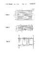
- FIG. 2is a schematic view, on an enlarged scale, of another embodiment of a soot filter arrangement in accordance with the present invention provided with several radial feed connections and one radial discharge connection;
- FIG. 3is an enlarged detailed view of an arrangement and construction of a support pipe of the soot filter arrangement of FIG. 2;
- FIG. 4is a longitudinal cross-sectional view through a soot filter arrangement corresponding to FIG. 2;
- FIG. 5is a cross-sectional view, on an enlarged scale, taken along the line of V--V of FIG. 4;
- FIG. 6is a longitudinal cross-sectional view through a supporting pipe and cross-winding of a filter material in accordance with the present invention.
- FIG. 7is a top view of the cross-winding of FIG. 6.
- a soot filter adapted to be disposed in an exhaust flow or exhaust gas stream of an internal combustion engineincludes a housing generally designated by the reference numeral 1 having at one end thereof a raidally connected feed connection or nipple 2 and at the other end a central axially directed discharge connection or nipple 3.
- a plurality of support pipes 4, provided with passage openings,are arranged in the housing 1 at a mutual spacing and are disposed in a parallel relationship with respect to one another.
- Filter material 5consisting of a wound thread of spun silicon dioxide or silica fibers is arranged on each of the support pipes 4.
- the support pipes 4are sealed toward a space 6 disposed in a zone of the feed connection 2 and open at the other end toward a space 7 disposed in a region of the discharge connection 3.
- Walls 8are disposed between the support pipes 4 at the open ends thereof in order to prevent exhaust gas, entering the space 6, from passing in between the support pipes 4 and along the latter directly into the space 7.
- the exhaust gasmust enter the support pipes 4 in a manner shown by the arrows 9 through the filter material 5 and then pass from the support pipes 4 into the space 7.
- the soot filter arrangement of FIG. 2includes a housing generally designated by the reference numeral 1' which is provided with a plurality of radial feed connections or nipples 2' for direct connection to an exhaust member of an internal combustion engine, such as, for example, an exhaust manifold, and a radial discharge connection 3'.
- Support pipes 4are disposed within the housing 1' with a filter material 5 being arranged on the respective support pipes.
- One end of the support pipes 4is unilaterally connected to an end wall of the housing 1', with the other end of the respective support pipes 4 being open toward the space 7 in a zone of the discharge connection 3'.
- Walls 8force the exhaust gases entering the housing 1' to flow through the filter material 5 into the support pipes 4 so only those exhaust gases may leave the housing 1' from which soot and other contaminants have been deposited in the filter material 5.
- Outwardly projecting corrugations 10are provided on the housing in order to enable a compensation for expansion and shrinking of the housing 1'.
- each support pipe 4 of the filter arrangement of FIG. 2is welded to the wall 8 with the other end of the support pipe being merely pushed onto a nipple 11 fixedly mounted at the housing wall 1a so as to compensate for thermal expansions.
- Support pipe 4is provided with a plurality of passage openings 12, the number and size of which may be adapted so as to attain maximally identical flow velocities in the filter without an appreciable pressure loss.
- Outwardly directed peripheral corrugations 13are provided at each of the support pipes 4, with the corrugations 13 serving for a positional stabilization of the filter material 5.
- bushing numbers 14may be arranged in the housing 1 or 1' for enabling an insertion of penetrating bolts or screws through the housing.
- the filter material 5is a thread 15 of spun silicon dioxide or silica fibers wound onto the support pipes 4.
- the thread 15may be roughened and a thread spacing of the cross-wound filter body ranges between 0.2 and 1 mm.
- the diameter of the thread 15ranges between 0.7 and 1 mm., and the fibers of which the thread 15 is spun have a diameter of about 9 ⁇ m.
Landscapes
- Engineering & Computer Science (AREA)
- Chemical & Material Sciences (AREA)
- Combustion & Propulsion (AREA)
- Mechanical Engineering (AREA)
- General Engineering & Computer Science (AREA)
- Processes For Solid Components From Exhaust (AREA)
- Exhaust Gas After Treatment (AREA)
- Filtering Of Dispersed Particles In Gases (AREA)
Abstract
Description
Claims (19)
Applications Claiming Priority (2)
| Application Number | Priority Date | Filing Date | Title |
|---|---|---|---|
| DE3007642ADE3007642C2 (en) | 1980-02-29 | 1980-02-29 | Soot filter in the exhaust gas flow of an internal combustion engine |
| DE3007642 | 1980-02-29 |
Publications (1)
| Publication Number | Publication Date |
|---|---|
| US4324572Atrue US4324572A (en) | 1982-04-13 |
Family
ID=6095858
Family Applications (1)
| Application Number | Title | Priority Date | Filing Date |
|---|---|---|---|
| US06/237,899Expired - LifetimeUS4324572A (en) | 1980-02-29 | 1981-02-25 | Soot filter for an exhaust arrangement of an internal combustion engine |
Country Status (5)
| Country | Link |
|---|---|
| US (1) | US4324572A (en) |
| DE (1) | DE3007642C2 (en) |
| FR (1) | FR2477222B1 (en) |
| GB (1) | GB2070972B (en) |
| SE (1) | SE453213B (en) |
Cited By (36)
| Publication number | Priority date | Publication date | Assignee | Title |
|---|---|---|---|---|
| US4436535A (en) | 1981-03-21 | 1984-03-13 | Filterwerk Mann & Hummel Gmbh | Method and device for removing soot from exhaust gases |
| US4478618A (en)* | 1983-08-01 | 1984-10-23 | General Motors Corporation | Diesel exhaust particulate trap with plural filter tubes |
| US4636232A (en)* | 1985-12-16 | 1987-01-13 | Amway Corporation | Filter stack |
| US4670233A (en)* | 1984-10-04 | 1987-06-02 | Filterwerk Mann & Hummel Gmbh | Method of removing soot which has been trapped in an exhaust gas filter of an internal combustion engine |
| US4811559A (en)* | 1986-11-03 | 1989-03-14 | Man Nutzfahrzeuge Gmbh | Apparatus for removing soot from the exhaust gases of an internal combustion engine |
| US4948398A (en)* | 1989-04-28 | 1990-08-14 | Ceco Filters, Inc. | Multi-candle fiber mist eliminator |
| EP0358522A3 (en)* | 1988-09-08 | 1991-06-26 | Minnesota Mining And Manufacturing Company | Regenerable diesel particulate trap |
| US5042249A (en)* | 1989-05-05 | 1991-08-27 | Filterwerk Mann & Hummel Gmbh | Soot filter for cleaning the exhaust from an internal combustion engine |
| WO1992017688A1 (en)* | 1991-04-05 | 1992-10-15 | Minnesota Mining And Manufacturing Company | Concentric-tube diesel particulate filter |
| US5171341A (en)* | 1991-04-05 | 1992-12-15 | Minnesota Mining And Manufacturing Company | Concentric-tube diesel particulate filter |
| US5174969A (en)* | 1991-04-05 | 1992-12-29 | Minnesota Mining And Manufacturing Company | Roll-pack diesel particulate filter |
| US5180409A (en)* | 1992-01-30 | 1993-01-19 | Minnesota Mining And Manufacturing Company | Hot-gas-filtering fabric of spaced uncrimped support strands and crimped lofty fill yarns |
| US5190571A (en)* | 1992-05-29 | 1993-03-02 | Minnesota Mining And Manufacturing Company | Diesel particulate trap based on a mass of fibrous filter material formed with longitudinal tunnels filled with flexible strands |
| US5248482A (en)* | 1991-04-05 | 1993-09-28 | Minnesota Mining And Manufacturing Company | Diesel particulate trap of perforated tubes wrapped with cross-wound inorganic yarn to form four-sided filter traps |
| US5248481A (en)* | 1992-05-11 | 1993-09-28 | Minnesota Mining And Manufacturing Company | Diesel particulate trap of perforated tubes having laterally offset cross-wound wraps of inorganic yarn |
| US5258164A (en)* | 1991-04-05 | 1993-11-02 | Minnesota Mining And Manufacturing Company | Electrically regenerable diesel particulate trap |
| US5298046A (en)* | 1993-01-06 | 1994-03-29 | Minnesota Mining And Manufacturing Company | Diesel particulate filter element and filter |
| US5409669A (en)* | 1993-01-25 | 1995-04-25 | Minnesota Mining And Manufacturing Company | Electrically regenerable diesel particulate filter cartridge and filter |
| US5656048A (en)* | 1994-04-06 | 1997-08-12 | Minnesota Mining And Manufacturing Company | Electrically regenerable diesel particulate filter cartridge and filter |
| US5702494A (en)* | 1995-06-09 | 1997-12-30 | Minnesota Mining And Manufacturing Company | Airbag filter assembly and method of assembly thereof |
| US6284201B1 (en) | 1993-02-10 | 2001-09-04 | Alfred Buck | Apparatus for the catalytic purification of flowing gases, in particular exhaust gases of internal combustion engines |
| EP1316692A1 (en)* | 2001-11-28 | 2003-06-04 | Isuzu Motors Limited | Exhaust gas purification system and method for controlling regeneration thereof |
| US20040079060A1 (en)* | 2002-10-28 | 2004-04-29 | Alward Gordon S. | Ceramic exhaust filter |
| US20060272319A1 (en)* | 2005-06-02 | 2006-12-07 | Dettling Joseph C | Segregated catalyzed metallic wire filter for diesel soot filtration |
| US7211232B1 (en) | 2005-11-07 | 2007-05-01 | Geo2 Technologies, Inc. | Refractory exhaust filtering method and apparatus |
| US20070207070A1 (en)* | 2006-03-03 | 2007-09-06 | Bilal Zuberi | Catalytic exhaust filter device |
| US7444805B2 (en) | 2005-12-30 | 2008-11-04 | Geo2 Technologies, Inc. | Substantially fibrous refractory device for cleaning a fluid |
| US7451849B1 (en) | 2005-11-07 | 2008-11-18 | Geo2 Technologies, Inc. | Substantially fibrous exhaust screening system for motor vehicles |
| US20080315733A1 (en)* | 2007-06-22 | 2008-12-25 | Terry Bosch | Modular Monitor Support Apparatus |
| US20090190106A1 (en)* | 2008-01-29 | 2009-07-30 | Asml Holding Nv | Immersion lithography apparatus |
| US7572311B2 (en) | 2002-10-28 | 2009-08-11 | Geo2 Technologies, Inc. | Highly porous mullite particulate filter substrate |
| US7574796B2 (en) | 2002-10-28 | 2009-08-18 | Geo2 Technologies, Inc. | Nonwoven composites and related products and methods |
| US7582270B2 (en) | 2002-10-28 | 2009-09-01 | Geo2 Technologies, Inc. | Multi-functional substantially fibrous mullite filtration substrates and devices |
| US7682578B2 (en) | 2005-11-07 | 2010-03-23 | Geo2 Technologies, Inc. | Device for catalytically reducing exhaust |
| US7682577B2 (en) | 2005-11-07 | 2010-03-23 | Geo2 Technologies, Inc. | Catalytic exhaust device for simplified installation or replacement |
| US7722828B2 (en) | 2005-12-30 | 2010-05-25 | Geo2 Technologies, Inc. | Catalytic fibrous exhaust system and method for catalyzing an exhaust gas |
Families Citing this family (16)
| Publication number | Priority date | Publication date | Assignee | Title |
|---|---|---|---|---|
| DE3538105A1 (en)* | 1985-10-26 | 1987-04-30 | Man Technologie Gmbh | FILTER FOR THE EXHAUST FLOW OF AN INTERNAL COMBUSTION ENGINE |
| DE3602154A1 (en)* | 1986-01-24 | 1987-07-30 | Man Technologie Gmbh | Particle filter for exhaust gases |
| US4925463A (en)* | 1986-05-30 | 1990-05-15 | Dieter Kuhnert | Exhaust gas cleaning system for diesel engines |
| DE3637331A1 (en)* | 1986-07-05 | 1988-05-11 | Man Nutzfahrzeuge Gmbh | Device for the removal of soot from the exhaust gases of an internal combustion engine, especially a diesel internal combustion engine |
| DE3622623A1 (en)* | 1986-07-05 | 1988-01-14 | Man Nutzfahrzeuge Gmbh | METHOD AND DEVICE FOR ELIMINATING SOOT SEPARATED IN AN EXHAUST FILTER OF AN INTERNAL COMBUSTION ENGINE |
| DE3731766A1 (en)* | 1987-09-22 | 1989-03-30 | Alfred Buck | Soot filter |
| DE3800723A1 (en)* | 1988-01-13 | 1989-07-27 | Daimler Benz Ag | Soot burn-off filter for diesel engines |
| DE3807539A1 (en)* | 1988-03-08 | 1989-09-21 | Peter Voelskow | Soot filters |
| DE3815148A1 (en)* | 1988-05-04 | 1989-11-16 | Eberspaecher J | Arrangement for mounting an exhaust gas filter in a metal housing |
| DE3823205A1 (en)* | 1988-07-08 | 1990-01-11 | Eberspaecher J | Soot-filter plug for the purification of exhaust gases and soot-filter arrangement formed from soot-filter plugs |
| DE4007724A1 (en)* | 1990-03-10 | 1991-09-12 | Ernst Apparatebau Gmbh & Co | SOOT FILTER FOR DIESEL ENGINES |
| DE4025568A1 (en)* | 1990-08-11 | 1992-02-13 | Daimler Benz Ag | Ceramic yarn material used for engine exhaust particle filter - has fibre tufts or loops projecting from yarn with yarn structure reducing splitting and breaking of fibre ends |
| DE4041735C1 (en)* | 1990-12-24 | 1991-11-07 | Mercedes-Benz Aktiengesellschaft, 7000 Stuttgart, De | Particle filter for exhaust gas from combustion engine - includes ceramic filter material sleeved support tubes arranged in parallel and having planar walls |
| DE59303868D1 (en)* | 1992-12-22 | 1996-10-24 | Leistritz Abgastech | Device for reducing exhaust gas pollutants, in particular for motor vehicles |
| DE4339686C1 (en)* | 1993-11-22 | 1994-11-03 | Daimler Benz Ag | Electrically heatable exhaust catalytic converter |
| CN112604404B (en)* | 2020-12-18 | 2022-04-05 | 盐城诚达环保工程有限公司 | Energy-saving safe pulse bag-type dust collector |
Citations (13)
| Publication number | Priority date | Publication date | Assignee | Title |
|---|---|---|---|---|
| GB189700618A (en)* | 1897-01-09 | 1897-11-13 | Auguste Emile Henri Loze | Improvements in Filters. |
| US2008560A (en)* | 1932-12-29 | 1935-07-16 | American Air Filter Co | Air filter medium |
| US2574221A (en)* | 1946-03-16 | 1951-11-06 | Johns Manville | Method of forming a multilayered mat of intercrossed filaments |
| US2780363A (en)* | 1952-12-22 | 1957-02-05 | Infilco Inc | Apparatus and process for washing diatomite type filters |
| US2823117A (en)* | 1953-11-23 | 1958-02-11 | L O F Glass Fibers Inc | Glass paper-calcium silicate |
| US3051602A (en)* | 1959-01-12 | 1962-08-28 | United States Gypsum Co | Multi-speed furnace traverse |
| US3398837A (en)* | 1964-12-03 | 1968-08-27 | Commercial Filters Corp | Impregnated self-supporting honeycombed filter cartridge |
| US3843561A (en)* | 1970-05-13 | 1974-10-22 | Universal Oil Prod Co | Mat of inorganic oxide fibers,its method of preparation and its impregnation with catalytic materials |
| US3857688A (en)* | 1971-10-27 | 1974-12-31 | Ppg Industries Inc | Lead filter |
| US3918945A (en)* | 1971-11-01 | 1975-11-11 | Ppg Industries Inc | Particulate lead trap |
| DE2810937A1 (en)* | 1978-03-14 | 1979-09-27 | Heinz Hoelter | Inorganic fibres filter for hot gases - consists of needle felt which contains ceramic fibres e.g. aluminosilicate |
| US4205971A (en)* | 1977-11-15 | 1980-06-03 | Daimler-Benz Aktiengesellschaft | Soot filter in the exhaust gas flow of air-compressing internal combustion engines |
| US4248929A (en)* | 1979-10-24 | 1981-02-03 | Monsanto Company | Filter media coated with flame resistant compositions |
Family Cites Families (4)
| Publication number | Priority date | Publication date | Assignee | Title |
|---|---|---|---|---|
| GB308790A (en)* | 1928-03-31 | 1930-05-29 | Deutsche Gasgluehlicht-Auer-Gesellschaft M.B.H. | |
| FR1337630A (en)* | 1961-10-23 | 1963-09-13 | Berliet Automobiles | Method and device for filtering and catalytic purification of exhaust gases containing solid components |
| FR2097502A5 (en)* | 1970-07-09 | 1972-03-03 | Tecalemit | |
| DE2322990B2 (en)* | 1973-05-08 | 1978-05-24 | Purolator Filter Gmbh, 7110 Oehringen | Filters for exhaust gas recirculation systems of internal combustion engines |
- 1980
- 1980-02-29DEDE3007642Apatent/DE3007642C2/ennot_activeExpired
- 1981
- 1981-02-23GBGB8105682Apatent/GB2070972B/ennot_activeExpired
- 1981-02-25USUS06/237,899patent/US4324572A/ennot_activeExpired - Lifetime
- 1981-02-27FRFR8103934Apatent/FR2477222B1/ennot_activeExpired
- 1981-02-27SESE8101312Apatent/SE453213B/ennot_activeIP Right Cessation
Patent Citations (13)
| Publication number | Priority date | Publication date | Assignee | Title |
|---|---|---|---|---|
| GB189700618A (en)* | 1897-01-09 | 1897-11-13 | Auguste Emile Henri Loze | Improvements in Filters. |
| US2008560A (en)* | 1932-12-29 | 1935-07-16 | American Air Filter Co | Air filter medium |
| US2574221A (en)* | 1946-03-16 | 1951-11-06 | Johns Manville | Method of forming a multilayered mat of intercrossed filaments |
| US2780363A (en)* | 1952-12-22 | 1957-02-05 | Infilco Inc | Apparatus and process for washing diatomite type filters |
| US2823117A (en)* | 1953-11-23 | 1958-02-11 | L O F Glass Fibers Inc | Glass paper-calcium silicate |
| US3051602A (en)* | 1959-01-12 | 1962-08-28 | United States Gypsum Co | Multi-speed furnace traverse |
| US3398837A (en)* | 1964-12-03 | 1968-08-27 | Commercial Filters Corp | Impregnated self-supporting honeycombed filter cartridge |
| US3843561A (en)* | 1970-05-13 | 1974-10-22 | Universal Oil Prod Co | Mat of inorganic oxide fibers,its method of preparation and its impregnation with catalytic materials |
| US3857688A (en)* | 1971-10-27 | 1974-12-31 | Ppg Industries Inc | Lead filter |
| US3918945A (en)* | 1971-11-01 | 1975-11-11 | Ppg Industries Inc | Particulate lead trap |
| US4205971A (en)* | 1977-11-15 | 1980-06-03 | Daimler-Benz Aktiengesellschaft | Soot filter in the exhaust gas flow of air-compressing internal combustion engines |
| DE2810937A1 (en)* | 1978-03-14 | 1979-09-27 | Heinz Hoelter | Inorganic fibres filter for hot gases - consists of needle felt which contains ceramic fibres e.g. aluminosilicate |
| US4248929A (en)* | 1979-10-24 | 1981-02-03 | Monsanto Company | Filter media coated with flame resistant compositions |
Cited By (44)
| Publication number | Priority date | Publication date | Assignee | Title |
|---|---|---|---|---|
| US4436535A (en) | 1981-03-21 | 1984-03-13 | Filterwerk Mann & Hummel Gmbh | Method and device for removing soot from exhaust gases |
| US4478618A (en)* | 1983-08-01 | 1984-10-23 | General Motors Corporation | Diesel exhaust particulate trap with plural filter tubes |
| US4670233A (en)* | 1984-10-04 | 1987-06-02 | Filterwerk Mann & Hummel Gmbh | Method of removing soot which has been trapped in an exhaust gas filter of an internal combustion engine |
| US4636232A (en)* | 1985-12-16 | 1987-01-13 | Amway Corporation | Filter stack |
| US4811559A (en)* | 1986-11-03 | 1989-03-14 | Man Nutzfahrzeuge Gmbh | Apparatus for removing soot from the exhaust gases of an internal combustion engine |
| EP0358522A3 (en)* | 1988-09-08 | 1991-06-26 | Minnesota Mining And Manufacturing Company | Regenerable diesel particulate trap |
| US4948398A (en)* | 1989-04-28 | 1990-08-14 | Ceco Filters, Inc. | Multi-candle fiber mist eliminator |
| US5042249A (en)* | 1989-05-05 | 1991-08-27 | Filterwerk Mann & Hummel Gmbh | Soot filter for cleaning the exhaust from an internal combustion engine |
| US5174969A (en)* | 1991-04-05 | 1992-12-29 | Minnesota Mining And Manufacturing Company | Roll-pack diesel particulate filter |
| US5258164A (en)* | 1991-04-05 | 1993-11-02 | Minnesota Mining And Manufacturing Company | Electrically regenerable diesel particulate trap |
| WO1992017688A1 (en)* | 1991-04-05 | 1992-10-15 | Minnesota Mining And Manufacturing Company | Concentric-tube diesel particulate filter |
| US5171341A (en)* | 1991-04-05 | 1992-12-15 | Minnesota Mining And Manufacturing Company | Concentric-tube diesel particulate filter |
| US5248482A (en)* | 1991-04-05 | 1993-09-28 | Minnesota Mining And Manufacturing Company | Diesel particulate trap of perforated tubes wrapped with cross-wound inorganic yarn to form four-sided filter traps |
| US5180409A (en)* | 1992-01-30 | 1993-01-19 | Minnesota Mining And Manufacturing Company | Hot-gas-filtering fabric of spaced uncrimped support strands and crimped lofty fill yarns |
| WO1993014859A1 (en)* | 1992-01-30 | 1993-08-05 | Minnesota Mining And Manufacturing Company | Hot-gas-filtering fabric of spaced uncrimped support strands and crimped lofty fill yarns |
| US5248481A (en)* | 1992-05-11 | 1993-09-28 | Minnesota Mining And Manufacturing Company | Diesel particulate trap of perforated tubes having laterally offset cross-wound wraps of inorganic yarn |
| US5190571A (en)* | 1992-05-29 | 1993-03-02 | Minnesota Mining And Manufacturing Company | Diesel particulate trap based on a mass of fibrous filter material formed with longitudinal tunnels filled with flexible strands |
| US5298046A (en)* | 1993-01-06 | 1994-03-29 | Minnesota Mining And Manufacturing Company | Diesel particulate filter element and filter |
| US5409669A (en)* | 1993-01-25 | 1995-04-25 | Minnesota Mining And Manufacturing Company | Electrically regenerable diesel particulate filter cartridge and filter |
| US6284201B1 (en) | 1993-02-10 | 2001-09-04 | Alfred Buck | Apparatus for the catalytic purification of flowing gases, in particular exhaust gases of internal combustion engines |
| US5656048A (en)* | 1994-04-06 | 1997-08-12 | Minnesota Mining And Manufacturing Company | Electrically regenerable diesel particulate filter cartridge and filter |
| US5702494A (en)* | 1995-06-09 | 1997-12-30 | Minnesota Mining And Manufacturing Company | Airbag filter assembly and method of assembly thereof |
| EP1316692A1 (en)* | 2001-11-28 | 2003-06-04 | Isuzu Motors Limited | Exhaust gas purification system and method for controlling regeneration thereof |
| CN100393992C (en)* | 2001-11-28 | 2008-06-11 | 五十铃自动车株式会社 | Exhaust purification system and regeneration control method thereof |
| US7582270B2 (en) | 2002-10-28 | 2009-09-01 | Geo2 Technologies, Inc. | Multi-functional substantially fibrous mullite filtration substrates and devices |
| US20050191218A1 (en)* | 2002-10-28 | 2005-09-01 | Geo2 Technologies, Inc. | Ceramic diesel exhaust filters |
| US6946013B2 (en) | 2002-10-28 | 2005-09-20 | Geo2 Technologies, Inc. | Ceramic exhaust filter |
| US7578979B2 (en) | 2002-10-28 | 2009-08-25 | Geo2 Technologies, Inc. | Ceramic diesel exhaust filters |
| US20040079060A1 (en)* | 2002-10-28 | 2004-04-29 | Alward Gordon S. | Ceramic exhaust filter |
| US20080171650A1 (en)* | 2002-10-28 | 2008-07-17 | Alward Gordon S | Nonwoven Composites and Related Products and Methods |
| US7574796B2 (en) | 2002-10-28 | 2009-08-18 | Geo2 Technologies, Inc. | Nonwoven composites and related products and methods |
| US7572416B2 (en) | 2002-10-28 | 2009-08-11 | Geo2 Technologies, Inc | Nonwoven composites and related products and methods |
| US7572311B2 (en) | 2002-10-28 | 2009-08-11 | Geo2 Technologies, Inc. | Highly porous mullite particulate filter substrate |
| US20060272319A1 (en)* | 2005-06-02 | 2006-12-07 | Dettling Joseph C | Segregated catalyzed metallic wire filter for diesel soot filtration |
| US7682578B2 (en) | 2005-11-07 | 2010-03-23 | Geo2 Technologies, Inc. | Device for catalytically reducing exhaust |
| US7682577B2 (en) | 2005-11-07 | 2010-03-23 | Geo2 Technologies, Inc. | Catalytic exhaust device for simplified installation or replacement |
| US7451849B1 (en) | 2005-11-07 | 2008-11-18 | Geo2 Technologies, Inc. | Substantially fibrous exhaust screening system for motor vehicles |
| US7211232B1 (en) | 2005-11-07 | 2007-05-01 | Geo2 Technologies, Inc. | Refractory exhaust filtering method and apparatus |
| US7722828B2 (en) | 2005-12-30 | 2010-05-25 | Geo2 Technologies, Inc. | Catalytic fibrous exhaust system and method for catalyzing an exhaust gas |
| US7444805B2 (en) | 2005-12-30 | 2008-11-04 | Geo2 Technologies, Inc. | Substantially fibrous refractory device for cleaning a fluid |
| US20070207070A1 (en)* | 2006-03-03 | 2007-09-06 | Bilal Zuberi | Catalytic exhaust filter device |
| US7563415B2 (en) | 2006-03-03 | 2009-07-21 | Geo2 Technologies, Inc | Catalytic exhaust filter device |
| US20080315733A1 (en)* | 2007-06-22 | 2008-12-25 | Terry Bosch | Modular Monitor Support Apparatus |
| US20090190106A1 (en)* | 2008-01-29 | 2009-07-30 | Asml Holding Nv | Immersion lithography apparatus |
Also Published As
| Publication number | Publication date |
|---|---|
| SE8101312L (en) | 1981-08-30 |
| DE3007642C2 (en) | 1985-01-31 |
| FR2477222A1 (en) | 1981-09-04 |
| GB2070972B (en) | 1984-02-22 |
| GB2070972A (en) | 1981-09-16 |
| FR2477222B1 (en) | 1987-03-06 |
| SE453213B (en) | 1988-01-18 |
| DE3007642A1 (en) | 1981-09-10 |
Similar Documents
| Publication | Publication Date | Title |
|---|---|---|
| US4324572A (en) | Soot filter for an exhaust arrangement of an internal combustion engine | |
| US4693338A (en) | Exhaust muffler for a motor vehicle or the like | |
| US4002433A (en) | Heat shield for a catalytic emission control device | |
| EP0724070B1 (en) | Honeycomb catalytic converter | |
| JP2694389B2 (en) | Metal honeycomb bodies, especially catalyst carrier bodies retained in inner and outer jacket tubes | |
| EP0690212B1 (en) | A method for utilising a silencer unit and an arrangement for applying the method in a large diesel engine | |
| EP2187013B1 (en) | Construction for an exhaust after treatment device | |
| DE50010423D1 (en) | Conduit for exhaust pipes of motor vehicles | |
| WO1994007588A1 (en) | Heat-resistant filter | |
| US11623180B2 (en) | Catalytic converter | |
| US3994130A (en) | Exhaust manifold assembly with catalytic converter | |
| US4151717A (en) | Catalytic converter apparatus for engine | |
| JP3318696B2 (en) | Exhaust gas purification device for internal combustion engine | |
| JP2009052441A (en) | Exhaust purification device | |
| US20050142043A1 (en) | Hot end systems including an insertable inner cone | |
| JPH06280555A (en) | Supporting construction of exhaust pipe for vehicle | |
| JPS6114568Y2 (en) | ||
| JP2007100608A (en) | Exhaust system of engine | |
| WO1991007575A1 (en) | Exhaust system | |
| JP3277801B2 (en) | Exhaust gas purification device | |
| JPH0752328Y2 (en) | Exhaust purification catalyst | |
| JPH0610134Y2 (en) | Catalyst converter | |
| JPH0716010Y2 (en) | Exhaust gas purification device for multi-cylinder internal combustion engine | |
| JP3146136B2 (en) | Silencer | |
| JPS6215460Y2 (en) |
Legal Events
| Date | Code | Title | Description |
|---|---|---|---|
| AS | Assignment | Owner name:FILTERWERK MANN & HUMMEL GMBH 7140 LUDWIGSBURG, GE Free format text:ASSIGNMENT OF ASSIGNORS INTEREST.;ASSIGNORS:ERDMANNSDORFER HANS;BERGMANN HORST;DAUDEL HELMUT;REEL/FRAME:003870/0322;SIGNING DATES FROM 19801219 TO 19810114 Owner name:DAIMLER-BENZ AKTIENGESELLSCHAFT , 7000 STUTTGART 6 Free format text:ASSIGNMENT OF ASSIGNORS INTEREST.;ASSIGNORS:ERDMANNSDORFER HANS;BERGMANN HORST;DAUDEL HELMUT;REEL/FRAME:003870/0322;SIGNING DATES FROM 19801219 TO 19810114 | |
| STCF | Information on status: patent grant | Free format text:PATENTED CASE | |
| FEPP | Fee payment procedure | Free format text:MAINTENANCE FEE REMINDER MAILED (ORIGINAL EVENT CODE: REM.); ENTITY STATUS OF PATENT OWNER: LARGE ENTITY | |
| FEPP | Fee payment procedure | Free format text:SURCHARGE FOR LATE PAYMENT, PL 96-517 (ORIGINAL EVENT CODE: M176); ENTITY STATUS OF PATENT OWNER: LARGE ENTITY | |
| MAFP | Maintenance fee payment | Free format text:PAYMENT OF MAINTENANCE FEE, 4TH YEAR, PL 96-517 (ORIGINAL EVENT CODE: M170); ENTITY STATUS OF PATENT OWNER: LARGE ENTITY Year of fee payment:4 | |
| MAFP | Maintenance fee payment | Free format text:PAYMENT OF MAINTENANCE FEE, 8TH YEAR, PL 96-517 (ORIGINAL EVENT CODE: M171); ENTITY STATUS OF PATENT OWNER: LARGE ENTITY Year of fee payment:8 | |
| MAFP | Maintenance fee payment | Free format text:PAYMENT OF MAINTENANCE FEE, 12TH YEAR, LARGE ENTITY (ORIGINAL EVENT CODE: M185); ENTITY STATUS OF PATENT OWNER: LARGE ENTITY Year of fee payment:12 | |
| FEPP | Fee payment procedure | Free format text:PAYOR NUMBER ASSIGNED (ORIGINAL EVENT CODE: ASPN); ENTITY STATUS OF PATENT OWNER: LARGE ENTITY |