US4323723A - Surface mounted outlet unit - Google Patents
Surface mounted outlet unitDownload PDFInfo
- Publication number
- US4323723A US4323723AUS06/137,545US13754580AUS4323723AUS 4323723 AUS4323723 AUS 4323723AUS 13754580 AUS13754580 AUS 13754580AUS 4323723 AUS4323723 AUS 4323723A
- Authority
- US
- United States
- Prior art keywords
- bottom wall
- end walls
- cover member
- base member
- outlet unit
- Prior art date
- Legal status (The legal status is an assumption and is not a legal conclusion. Google has not performed a legal analysis and makes no representation as to the accuracy of the status listed.)
- Expired - Lifetime
Links
Images


Classifications
- H—ELECTRICITY
- H02—GENERATION; CONVERSION OR DISTRIBUTION OF ELECTRIC POWER
- H02G—INSTALLATION OF ELECTRIC CABLES OR LINES, OR OF COMBINED OPTICAL AND ELECTRIC CABLES OR LINES
- H02G3/00—Installations of electric cables or lines or protective tubing therefor in or on buildings, equivalent structures or vehicles
- H02G3/02—Details
- H02G3/08—Distribution boxes; Connection or junction boxes
- H02G3/18—Distribution boxes; Connection or junction boxes providing line outlets
- H02G3/185—Floor outlets and access cups
Definitions
- This inventionrelates to an improved electrical outlet unit for use in connection with underfloor wiring systems for buildings; and more particularly to an improved outlet unit of the surface mounted type providing access to power and communications wiring.
- the floors of modern buildingsincorporate underfloor metal conduits or raceways for distributing wiring of different services, such as, high voltage power wiring and low voltage communications wiring.
- the power wiring and the communications wiringare housed in separate conduits.
- outlets of REILAND, GURITZ, FORK and KLINKMAN et alconsist of a multiplicity of components which reinstates the use of various fastening means to secure the parts together.
- the outlet unitsare relatively expensive to manufacture, and require a considerable length of time to assemble the parts for shipment, and to disassemble and reassemble the parts during installation in a building floor.
- the outlet unit of BROTHERHOODprovides access to a single service.
- the cover and base membersare extruded elements, whereby advantage is taken of the economies provided by extrusion techniques.
- the principal object of this inventionis to provide an improved floor-mounted outlet unit providing segregated compartments offering above-the floor access to different electrical services.
- Another object of this inventionis to provide a floor-mounted outlet unit having two principal components which comprise segments of different metal extrusions, thereby taking advantage of the economies offered by conventional extrusion techniques.
- an improved outlet unitcomposed of two principal interfitting components, that is, a base member and a cover member.
- the base membercomprises a segment of a first metal extrusion having a U-shaped profile and includes a bottom wall, upstanding opposite end walls, and an upstanding partition intermediate of the end walls.
- the cover membercomprises a segment of a second metal extrusion having an inverted U-shaped profile and includes a top wall and depending opposite sidewalls. When assembled, the cover member straddles the base member such that the opposite sidewalls thereof confront opposite end edges of the end walls and the bottom wall of the base member. The cover member cooperates with the partition to define segregated compartments in which electrical connections can be made. Means is provided for securing the cover member to the base member.
- inlet openingsare provided in the bottom wall, at least one in each of the compartments, for admitting power and communications wiring into the compartments.
- Outlet openingsare provided, at least one in each of the end walls of the base member.
- the opening or openings in one end wallmay accommodate the projecting face portions of special or conventional receptacles.
- the outlet opening or openings provided in the other end wallmay accommodate suitable bushings or grommets through which multiple conductor cables, such as telephone cables, extend out of the unit.
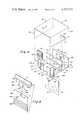
- FIG. 1is a fragmentary isometric view illustrating the present outlet unit installed in a building floor
- FIG. 2is an isometric view of two metal extrusions, segments of which constitute the cover and base member of the present outlet unit;
- FIG. 3is an isometric exploded view of the present outlet unit illustrating the components thereof;
- FIG. 4is a cross-sectional view, taken along the line 4--4 of FIG. 1;
- FIG. 5is a fragmentary cross-sectional view, similar to FIG. 4, illustrating alternative means for securing the base member to the substructure;
- FIG. 6is a fragmentary isometric view illustrating an alternative receptacle support arrangement.
- FIG. 1illustrates an above-the-floor dual service outlet unit 10 of this invention.
- the unit 10is mounted on the upper surface of a floor 12 of which only a fragment of a layer of concrete 14 and of a decorative covering, such as a carpet 16, are shown.
- the unit 10offers--at one location in the floor 12--accessibility to electrical power by way of a duplex receptacle 18 presented at one end face 20 for plug connections; and accessibility to telephone and signal services, by way of telephone and signal cables 22, 24, respectively, which extend from the opposite end face 26.
- the unit 10(FIG. 1) is assembled from base and cover members 28, 30.
- the base and cover members 28, 30comprise segments S 1 and S 2 of first and second metal extrusions 32, 34, respectively.
- the segments S 1 , S 2are illustrated in full lines whereas the remaining length of the metal extrusions 32, 34 are shown in dash-dot outline.
- the first extrusion 32has a generally U-shaped profile providing the base member 28 with a bottom wall 36, upstanding opposite end walls 38, 40, and an upstanding partition 42 intermediate of the end walls 38, 40.
- the partition 42cooperates with the end walls 38, 40 and with the bottom wall 36 to define separate U-shaped channels 64, 66.
- the partition 42has a rib 44 formed integrally therewith substantially parallel with the bottom wall 36.
- the rib 44is provided with an axially extending groove 46 formed therein during the extrusion process. As will become apparent, the opposite ends of the groove 46 receive fasteners which secure the cover member 30 to the base member 28.
- a depending flange 48is provided serving as one member of a two member partition.
- the flange 48is conveniently formed integrally with the bottom wall 36 and preferably is aligned with the partition 42.
- the second metal extrusion 34has a generally inverted U-shaped profile providing the cover member 30 with a top wall 50 and depending opposite sidewalls 52, 54.
- the length 56 of the base member 28corresponds substantially with the interior width 60 of the cover member 30; and that the length 62 of the cover member 30 is at least equal to and preferably slightly greater than the width 58 of the base member 28.
- the arrangementis such that the cover member 30 is adapted to straddle the base member 28 such that the opposite sidewalls 52, 54 thereof confront opposite end edges of the opposite end walls 38, 40 and of the bottom wall 36.
- the cover membercaps the U-shaped channels 64, 66 and converts the same into segregated compartments later to be identified.
- the segments S 1 and S 2which are cut from the extrusions 32, 34, undergo fabricating steps to adapt the same for use as the base and cover members 28, 30.
- the fabrication stepsprovide various openings now to be described in connection with FIG. 3.
- a countersunk opening 64is provided in each of the sidewalls 52, 54.
- the openings 64are located so as to be axially aligned with the opposite ends of the groove 46 when the base and cover members 28, 30 are assembled.
- Each opening 64receives a fastener 66 (only one illustrated in FIG. 3) which secures the cover 30 to the base 28.
- Spaced-apart apertures 68 and a screw-receiving opening 70 intermediate thereofare provided in the end wall 38.
- the opening 68 and the aperture 70adapt the end wall 38 to receive and retain the duplex receptacle 18 (FIG. 1).
- An inlet opening 72is provided in that portion of the bottom wall 36 presented within the U-shaped channel 64. The inlet opening 72 allows passage of power wiring into the channel 64 for connection to the duplex receptacle 18.
- the end wall 40is provided with at least and preferably two notches 74 adapted to receive grommets 76 (only one illustrated in FIG. 3).
- the grommets 76may present concentric weakened areas 78 certain of which are cut away to allow passage of telephone or signal cables.
- An inlet opening 80is provided in that portion of the bottom wall 36 presented within the U-shaped channel 66. The inlet opening 80 allows passage of telephone and signal cables from the space below the base member 28 into the U-shaped channel 66.
- Fastening meansalso are provided for securing the base member 28 to a substructure.
- the fastening meanscomprises two sets of spaced-apart screw-receiving openings 82, provided in the bottom wall 36, one set adjacent to each of the end walls 38, 40.
- the openings 82are adapted to receive fasteners 84 (only one illustrated in FIG. 3) which are engageable with a substructure.
- the width of the flange 48may be adjusted to correspond with an opening in a supporting substructure. As can be seen in FIG. 3, the width adjustment may be made by cutting away opposite end portions of the flange 48.
- a partition flange 86 having an opening 92is provided which cooperates with the flange 48 to provide full-height partitioning of a subjacent cavity.
- Fastening meanssuch as cooperating fastener 90 and nut 94, is provided for positively securing the partition flange 86 in vertically adjusted relation with respect to the flange 48.
- FIG. 4illustrates the outlet unit 10 installed on the floor 12.
- the base member 28is secured to an activating ring 96 by means of the fasteners 84.
- Power wiring 98extends from a raceway 100 into a power compartment 102 of an underfloor cavity 104 through the outlet opening 72 and is connected to the duplex receptacle 18.
- the receptacle 18is secured to the end wall 38 with the outlets thereof presented in the openings 68.
- a telephone cable 108extends from a second raceway 110 into a telephone/signal compartment 112 of the underfloor cavity 104.
- the flange 48 and the partition flange 86divide the underfloor cavity 104 into the power compartment 102 and the telephone/signal compartment 112.
- the upstanding flange 42 of the base member 28divides the interior of the unit 10 into a power compartment 102A and a telephone/signal compartment 112A.
- the arrangementis such that the power wiring 98 is completely segregated from the telephone/signal wiring 108.
- Alternative fastening means 117may be provided for securing the base member 28 to the activating ring 96.
- the fastening means 117comprises an L-shaped flange 118 formed integrally with the bottom wall 36 at a lower face thereof.
- the L-shaped flange 118includes a terminal portion 120 which is substantially parallel with the bottom wall 36 and which is engaged in hooked relation with a lower face 122 of the activating ring 96.
- the opposite end of the base member 28is secured to the activating ring by the fasteners 84.
- the fastening means 117may replace that set of the openings 82 and fasteners 84 situated next to either of the end walls 38, 40.
- the position of the fastening means 117 shown in FIG. 5is preferred since it avoids the introduction of screw fasteners which may be longer than necessary into the high tension power compartment 102.
- the outlet fitting 10may include a second receptacle offering semi-permanent type electrical connections to equipment which normally remains in a fixed position.
- the second receptacleshown in dotted outline at 106 in FIG. 4, may be mounted on the partition flange 86 after removing the knockouts 124 (FIG. 3).
- the second receptacle 106is accessible through the telephone/signal compartments 112, 112A after removing the cover 30.
- the electrical cord (not illustrated) which is connected to the receptacle 106may conveniently and neatly pass through a second grommet 76.
- FIG. 6An alternative arrangement for supporting the second receptacle 106 is illustrated in FIG. 6. Openings 68', 70' are provided in the flange 48 for receiving and supporting the receptacle 106 (not shown). Vertical adjustment of the partition flange 86' relative to the flange 48 is provided for by a central slot 124 and a series of break-off strips 126. The partition flange 86' is secured to the flange 48 by a fastener 128 which will pass through the slot 124 and into a threaded opening 130 in the flange 48. The central slot 124 allows slight vertical movement of the flange 86' relative to the flange 48. The height of the partition flange 86' is adjusted to match that of the cavity 104, by removing one or more of the strips 126.
Landscapes
- Engineering & Computer Science (AREA)
- Architecture (AREA)
- Civil Engineering (AREA)
- Structural Engineering (AREA)
- Connector Housings Or Holding Contact Members (AREA)
- Connection Or Junction Boxes (AREA)
- Installation Of Indoor Wiring (AREA)
Abstract
Description
Claims (11)
Priority Applications (4)
| Application Number | Priority Date | Filing Date | Title |
|---|---|---|---|
| US06/137,545US4323723A (en) | 1980-04-04 | 1980-04-04 | Surface mounted outlet unit |
| JP3238481AJPS56148116A (en) | 1980-04-04 | 1981-03-06 | Surface mounting type outlet unit |
| BR8101701ABR8101701A (en) | 1980-04-04 | 1981-03-23 | DOUBLE SERVICE SOCKET UNIT |
| MX186605AMX152608A (en) | 1980-04-04 | 1981-03-30 | IMPROVEMENTS TO FLOOR CONTACT UNIT FOR DISTRIBUTION OF ELECTRICAL ENERGY WIRING AND SIMILAR |
Applications Claiming Priority (1)
| Application Number | Priority Date | Filing Date | Title |
|---|---|---|---|
| US06/137,545US4323723A (en) | 1980-04-04 | 1980-04-04 | Surface mounted outlet unit |
Publications (1)
| Publication Number | Publication Date |
|---|---|
| US4323723Atrue US4323723A (en) | 1982-04-06 |
Family
ID=22477905
Family Applications (1)
| Application Number | Title | Priority Date | Filing Date |
|---|---|---|---|
| US06/137,545Expired - LifetimeUS4323723A (en) | 1980-04-04 | 1980-04-04 | Surface mounted outlet unit |
Country Status (4)
| Country | Link |
|---|---|
| US (1) | US4323723A (en) |
| JP (1) | JPS56148116A (en) |
| BR (1) | BR8101701A (en) |
| MX (1) | MX152608A (en) |
Cited By (35)
| Publication number | Priority date | Publication date | Assignee | Title |
|---|---|---|---|---|
| US4477694A (en)* | 1982-02-08 | 1984-10-16 | John E. Kohaut | Through-floor electrical outlet fitting |
| US4641222A (en)* | 1984-05-29 | 1987-02-03 | Motorola, Inc. | Mounting system for stress relief in surface mounted components |
| US4958047A (en)* | 1989-01-13 | 1990-09-18 | Square D Company | Monument fitting |
| US5003127A (en)* | 1989-05-12 | 1991-03-26 | Thomas & Betts Corporation | Interfloor power/communication connection apparatus |
| US5195288A (en)* | 1991-08-30 | 1993-03-23 | Butler Manufacturing Company | Floor fitting |
| US5203711A (en)* | 1991-10-01 | 1993-04-20 | Molex Incorporated | Modular interchangeable power distribution system |
| US5237128A (en)* | 1991-09-27 | 1993-08-17 | Hubbell Incorporated | Above-floor service fitting for poke-through wiring device |
| USD354671S (en) | 1991-08-30 | 1995-01-24 | Walker Systems, Inc. | Floor fitting |
| US5629496A (en)* | 1993-07-05 | 1997-05-13 | Aparellaje Electrico, S.A. | Device for adapting an electrical mechanism to a raceway means for electrical conductors |
| US5828001A (en)* | 1995-02-15 | 1998-10-27 | Guilford (Delaware), Inc. | Plastic junction box with receptacle boxes |
| USD405416S (en) | 1997-07-18 | 1999-02-09 | Byrne Norman R | Shaped power and data unit |
| US5920033A (en)* | 1994-05-12 | 1999-07-06 | Bosse, Jr.; John J. | Combined wall mount and electrical outlet box |
| US5952610A (en)* | 1994-05-12 | 1999-09-14 | Bosse, Jr.; John J. | Combined wall mount and electrical outlet box |
| US6042426A (en)* | 1996-11-13 | 2000-03-28 | Byrne; Norman R. | Multi-user electrical services outlet |
| US6091023A (en)* | 1998-01-21 | 2000-07-18 | O`Donnell; Patrick | Enclosure for interfacing electrical and control or communication devices |
| US6218613B1 (en)* | 1998-08-19 | 2001-04-17 | Leviton Manufacturing Co., Inc. | Divided standard device inch box |
| US6435364B1 (en)* | 1998-03-18 | 2002-08-20 | Rittal-Werk Rudolf Loh Gmbh & Co. Kg | Wall-mounted installation housing |
| US20040055774A1 (en)* | 2002-09-24 | 2004-03-25 | Bluegrass Products, L.L.C. | Exterior mounting block for electrical fixtures |
| US20040112622A1 (en)* | 2002-09-24 | 2004-06-17 | Michael Vagedes | Exterior mounting block for electrical fixtures |
| US6795300B1 (en) | 2002-09-13 | 2004-09-21 | Edward L. Holley | Roof-top mounted wiring portal assembly |
| US7032614B2 (en) | 2000-11-03 | 2006-04-25 | Applied Materials, Inc. | Facilities connection box for pre-facilitation of wafer fabrication equipment |
| US7063301B2 (en) | 2000-11-03 | 2006-06-20 | Applied Materials, Inc. | Facilities connection bucket for pre-facilitation of wafer fabrication equipment |
| US20070082588A1 (en)* | 2005-09-27 | 2007-04-12 | De Vries Nicholas | Methods and apparatus for coupling semiconductor device manufacturing equipment to the facilities of a manufacturing location |
| US20070215614A1 (en)* | 2006-03-06 | 2007-09-20 | Yazaki Corporation | Waterproof box |
| USD736159S1 (en) | 2013-04-15 | 2015-08-11 | Daniel P. Byrne | Electrical power unit for a work surface |
| USD739821S1 (en) | 2014-04-15 | 2015-09-29 | Norman R. Byrne | Power center for a work surface |
| US9148006B2 (en) | 2013-05-03 | 2015-09-29 | Norman R. Byrne | Interchangeable base system |
| USD761732S1 (en) | 2015-02-06 | 2016-07-19 | Norman R. Byrne | Electrical power unit |
| USD762175S1 (en) | 2015-02-06 | 2016-07-26 | Norman R. Byrne | Electrical power unit for a work surface |
| USD772817S1 (en)* | 2015-02-27 | 2016-11-29 | Premaco Limited | Recessed media hub |
| USD844565S1 (en)* | 2017-04-23 | 2019-04-02 | Ningbo Well Electric Appliance Co., Ltd. | Electrical socket |
| USD848371S1 (en) | 2017-05-17 | 2019-05-14 | Daniel P. Byrne | Electrical power unit for a work surface |
| US10547188B2 (en) | 2016-03-11 | 2020-01-28 | Norman R. Byrne | Furniture-mounted charging station |
| US10680392B2 (en) | 2017-07-24 | 2020-06-09 | Norman R. Byrne | Furniture-mounted electrical charging station |
| USD887363S1 (en) | 2018-01-24 | 2020-06-16 | Norman R. Byrne | Electrical power unit |
Families Citing this family (2)
| Publication number | Priority date | Publication date | Assignee | Title |
|---|---|---|---|---|
| JPS61134627U (en)* | 1985-02-12 | 1986-08-22 | ||
| JPH0735308Y2 (en)* | 1990-11-15 | 1995-08-09 | 松下電工株式会社 | Flat cable connector |
Citations (10)
| Publication number | Priority date | Publication date | Assignee | Title |
|---|---|---|---|---|
| US2420184A (en)* | 1944-11-03 | 1947-05-06 | Cutler Hammer Inc | Cover fastening device |
| US2887525A (en)* | 1956-09-25 | 1959-05-19 | Alexander J Lewus | Electrical wiring apparatus |
| US3047650A (en)* | 1959-06-24 | 1962-07-31 | Square D Co | Service fitting housing for under-floor wiring system |
| US3335214A (en)* | 1965-08-13 | 1967-08-08 | Brotherhood Donald Middleton | Electrical outlet |
| US3417191A (en)* | 1966-02-14 | 1968-12-17 | Robertson Co H H | Dual function electrical outlet and electrical distribution system utilizing the same |
| US3597523A (en)* | 1970-02-17 | 1971-08-03 | Kenneth E Guritz | Unted outlet boxes |
| USRE27549E (en) | 1971-05-15 | 1973-01-16 | Single and dual service fittings | |
| US3721762A (en)* | 1971-12-08 | 1973-03-20 | Plastic J Corp | Electrical raceway and decorative molding |
| US3728470A (en)* | 1971-09-27 | 1973-04-17 | W Maier | Electrical outlet box with cable connectors |
| US3751576A (en)* | 1972-04-13 | 1973-08-07 | Mac Fab Products | Plural-cell duct |
- 1980
- 1980-04-04USUS06/137,545patent/US4323723A/ennot_activeExpired - Lifetime
- 1981
- 1981-03-06JPJP3238481Apatent/JPS56148116A/enactivePending
- 1981-03-23BRBR8101701Apatent/BR8101701A/enunknown
- 1981-03-30MXMX186605Apatent/MX152608A/enunknown
Patent Citations (10)
| Publication number | Priority date | Publication date | Assignee | Title |
|---|---|---|---|---|
| US2420184A (en)* | 1944-11-03 | 1947-05-06 | Cutler Hammer Inc | Cover fastening device |
| US2887525A (en)* | 1956-09-25 | 1959-05-19 | Alexander J Lewus | Electrical wiring apparatus |
| US3047650A (en)* | 1959-06-24 | 1962-07-31 | Square D Co | Service fitting housing for under-floor wiring system |
| US3335214A (en)* | 1965-08-13 | 1967-08-08 | Brotherhood Donald Middleton | Electrical outlet |
| US3417191A (en)* | 1966-02-14 | 1968-12-17 | Robertson Co H H | Dual function electrical outlet and electrical distribution system utilizing the same |
| US3597523A (en)* | 1970-02-17 | 1971-08-03 | Kenneth E Guritz | Unted outlet boxes |
| USRE27549E (en) | 1971-05-15 | 1973-01-16 | Single and dual service fittings | |
| US3728470A (en)* | 1971-09-27 | 1973-04-17 | W Maier | Electrical outlet box with cable connectors |
| US3721762A (en)* | 1971-12-08 | 1973-03-20 | Plastic J Corp | Electrical raceway and decorative molding |
| US3751576A (en)* | 1972-04-13 | 1973-08-07 | Mac Fab Products | Plural-cell duct |
Cited By (46)
| Publication number | Priority date | Publication date | Assignee | Title |
|---|---|---|---|---|
| US4477694A (en)* | 1982-02-08 | 1984-10-16 | John E. Kohaut | Through-floor electrical outlet fitting |
| US4641222A (en)* | 1984-05-29 | 1987-02-03 | Motorola, Inc. | Mounting system for stress relief in surface mounted components |
| US4958047A (en)* | 1989-01-13 | 1990-09-18 | Square D Company | Monument fitting |
| US5003127A (en)* | 1989-05-12 | 1991-03-26 | Thomas & Betts Corporation | Interfloor power/communication connection apparatus |
| US5195288A (en)* | 1991-08-30 | 1993-03-23 | Butler Manufacturing Company | Floor fitting |
| USD354671S (en) | 1991-08-30 | 1995-01-24 | Walker Systems, Inc. | Floor fitting |
| US5237128A (en)* | 1991-09-27 | 1993-08-17 | Hubbell Incorporated | Above-floor service fitting for poke-through wiring device |
| US5203711A (en)* | 1991-10-01 | 1993-04-20 | Molex Incorporated | Modular interchangeable power distribution system |
| US5629496A (en)* | 1993-07-05 | 1997-05-13 | Aparellaje Electrico, S.A. | Device for adapting an electrical mechanism to a raceway means for electrical conductors |
| US5952610A (en)* | 1994-05-12 | 1999-09-14 | Bosse, Jr.; John J. | Combined wall mount and electrical outlet box |
| US6133524A (en)* | 1994-05-12 | 2000-10-17 | Boss Products Corporation | Combined wall mount and electrical outlet box |
| US5920033A (en)* | 1994-05-12 | 1999-07-06 | Bosse, Jr.; John J. | Combined wall mount and electrical outlet box |
| US6417447B1 (en) | 1994-05-12 | 2002-07-09 | Boss Products Corporation | Combined wall mount and electrical outlet box |
| US6303858B1 (en) | 1994-05-12 | 2001-10-16 | John J. Bosse, Jr. | Combined wall mount and electrical outlet box |
| US5828001A (en)* | 1995-02-15 | 1998-10-27 | Guilford (Delaware), Inc. | Plastic junction box with receptacle boxes |
| US6042426A (en)* | 1996-11-13 | 2000-03-28 | Byrne; Norman R. | Multi-user electrical services outlet |
| USD405416S (en) | 1997-07-18 | 1999-02-09 | Byrne Norman R | Shaped power and data unit |
| US6091023A (en)* | 1998-01-21 | 2000-07-18 | O`Donnell; Patrick | Enclosure for interfacing electrical and control or communication devices |
| US6414241B1 (en) | 1998-01-21 | 2002-07-02 | Christopher J. Carter | Enclosure for interfacing electrical and control or communication devices |
| US6435364B1 (en)* | 1998-03-18 | 2002-08-20 | Rittal-Werk Rudolf Loh Gmbh & Co. Kg | Wall-mounted installation housing |
| US6218613B1 (en)* | 1998-08-19 | 2001-04-17 | Leviton Manufacturing Co., Inc. | Divided standard device inch box |
| US7063301B2 (en) | 2000-11-03 | 2006-06-20 | Applied Materials, Inc. | Facilities connection bucket for pre-facilitation of wafer fabrication equipment |
| US7032614B2 (en) | 2000-11-03 | 2006-04-25 | Applied Materials, Inc. | Facilities connection box for pre-facilitation of wafer fabrication equipment |
| US6795300B1 (en) | 2002-09-13 | 2004-09-21 | Edward L. Holley | Roof-top mounted wiring portal assembly |
| US6723921B2 (en) | 2002-09-24 | 2004-04-20 | Bluegrass Products, Llc | Exterior mounting block for electrical fixtures |
| US6825414B2 (en) | 2002-09-24 | 2004-11-30 | Bluegrass Products, L.L.C. | Exterior mounting block for electrical fixtures |
| US20040112622A1 (en)* | 2002-09-24 | 2004-06-17 | Michael Vagedes | Exterior mounting block for electrical fixtures |
| US20040055774A1 (en)* | 2002-09-24 | 2004-03-25 | Bluegrass Products, L.L.C. | Exterior mounting block for electrical fixtures |
| US20070082588A1 (en)* | 2005-09-27 | 2007-04-12 | De Vries Nicholas | Methods and apparatus for coupling semiconductor device manufacturing equipment to the facilities of a manufacturing location |
| US20070215614A1 (en)* | 2006-03-06 | 2007-09-20 | Yazaki Corporation | Waterproof box |
| US7762415B2 (en)* | 2006-03-06 | 2010-07-27 | Yazaki Corporation | Waterproof box for a wiring harness connector |
| USD736159S1 (en) | 2013-04-15 | 2015-08-11 | Daniel P. Byrne | Electrical power unit for a work surface |
| USD744953S1 (en) | 2013-04-15 | 2015-12-08 | Norman R. Byrne | Electrical power unit for a work surface |
| US9148006B2 (en) | 2013-05-03 | 2015-09-29 | Norman R. Byrne | Interchangeable base system |
| USD739821S1 (en) | 2014-04-15 | 2015-09-29 | Norman R. Byrne | Power center for a work surface |
| USD761732S1 (en) | 2015-02-06 | 2016-07-19 | Norman R. Byrne | Electrical power unit |
| USD762175S1 (en) | 2015-02-06 | 2016-07-26 | Norman R. Byrne | Electrical power unit for a work surface |
| USD816037S1 (en) | 2015-02-06 | 2018-04-24 | Norman R. Byrne | Electrical power unit for a work surface |
| USD849686S1 (en) | 2015-02-06 | 2019-05-28 | Norman R. Byrne | Electrical power unit |
| USD772817S1 (en)* | 2015-02-27 | 2016-11-29 | Premaco Limited | Recessed media hub |
| US10547188B2 (en) | 2016-03-11 | 2020-01-28 | Norman R. Byrne | Furniture-mounted charging station |
| US11146083B2 (en) | 2016-03-11 | 2021-10-12 | Norman R. Byrne | Furniture-mounted charging station |
| USD844565S1 (en)* | 2017-04-23 | 2019-04-02 | Ningbo Well Electric Appliance Co., Ltd. | Electrical socket |
| USD848371S1 (en) | 2017-05-17 | 2019-05-14 | Daniel P. Byrne | Electrical power unit for a work surface |
| US10680392B2 (en) | 2017-07-24 | 2020-06-09 | Norman R. Byrne | Furniture-mounted electrical charging station |
| USD887363S1 (en) | 2018-01-24 | 2020-06-16 | Norman R. Byrne | Electrical power unit |
Also Published As
| Publication number | Publication date |
|---|---|
| MX152608A (en) | 1985-09-17 |
| JPS56148116A (en) | 1981-11-17 |
| BR8101701A (en) | 1981-10-06 |
Similar Documents
| Publication | Publication Date | Title |
|---|---|---|
| US4323723A (en) | Surface mounted outlet unit | |
| US7348487B2 (en) | Floor box with voltage divider | |
| US5546717A (en) | Access floor trench raceway | |
| US7262371B2 (en) | Modular raceway with base and integral divider | |
| US3303264A (en) | Dual service conduit and outlet system | |
| US5195288A (en) | Floor fitting | |
| US5024614A (en) | Surface accessible wiring system and assembly | |
| US6175078B1 (en) | Flush poke-through wiring fitting having a height adjustable data jack mounting bracket | |
| US4232183A (en) | Electrical connection system for panel structures | |
| US3453791A (en) | Underfloor electrical raceway crossover unit | |
| US2132400A (en) | Electrical wiring system for buildings | |
| US4373111A (en) | Service poles | |
| US20060117684A1 (en) | Modular raceway | |
| US4209660A (en) | Out-of-sight service fittings | |
| US3417191A (en) | Dual function electrical outlet and electrical distribution system utilizing the same | |
| US4297524A (en) | Electrical activating assembly and receptacle support means therefor | |
| US5839594A (en) | Thruway electrical outlet box system | |
| US20180166872A1 (en) | Floor box and method of installing | |
| US4931597A (en) | Junction boxes | |
| US4594826A (en) | Field-assembled raceway forming member | |
| US4932181A (en) | Base assembly for an open office partition panel | |
| US4847444A (en) | Electric outlet box holder | |
| US4577055A (en) | Power pole wiring assembly | |
| CA2068250C (en) | Above-floor service fitting for poke-through wiring device | |
| US6865851B2 (en) | Modular floor panels with enclosed wireway channels |
Legal Events
| Date | Code | Title | Description |
|---|---|---|---|
| AS | Assignment | Owner name:H.H. ROBERTSON COMPANY, TWO GATEWAY CENTER, PITTSB Free format text:ASSIGNMENT OF ASSIGNORS INTEREST.;ASSIGNORS:FORK, FRANK W.;KELLY, CHARLES J.;REEL/FRAME:003932/0168;SIGNING DATES FROM 19800508 TO 19800512 | |
| STCF | Information on status: patent grant | Free format text:PATENTED CASE | |
| AS | Assignment | Owner name:EQUITABLE BANK, NATIONAL ASSOCIATION, AS AGENT Free format text:SECURITY INTEREST;ASSIGNOR:H.H. ROBERTSON COMPANY;REEL/FRAME:005261/0382 Effective date:19891013 | |
| AS | Assignment | Owner name:WELLS FARGO BANK, N.A., A NATIONAL BANKING ASSOCIA Free format text:SECURITY INTEREST;ASSIGNOR:ROBERTSON-CECO CORPORATION, A DE CORP.;REEL/FRAME:005498/0434 Effective date:19901108 Owner name:WELLS FARGO BANK, N.A., A NATIONAL BANKING ASSOCIA Free format text:SECURITY INTEREST;ASSIGNOR:ROBERTSON CECO CORPORATION, A DE CORP.;REEL/FRAME:005617/0421 Effective date:19901108 Owner name:H. H. ROBERTSON, A CORP. OF DELAWARE, PENNSYLVANIA Free format text:RELEASED BY SECURED PARTY;ASSIGNOR:MARYLAND NATIONAL BANK;REEL/FRAME:005518/0120 Effective date:19901107 Owner name:H. H. ROBERTSON, A CORP. OF DELAWARE, PENNSYLVANIA Free format text:RELEASED BY SECURED PARTY;ASSIGNOR:FIRST CITY SECURITIES INC.;REEL/FRAME:005518/0137 Effective date:19901106 | |
| AS | Assignment | Owner name:ROBERTSON-CECO CORPORATION, A DE CORP. Free format text:ASSIGNMENT OF ASSIGNORS INTEREST. EFFECTIVE NOVEMBER 8, 1990;ASSIGNOR:H.H. ROBERTSON COMPANY;REEL/FRAME:005587/0020 Effective date:19901105 | |
| AS | Assignment | Owner name:WELLS FARGO BANK, N.A. A NATIONAL BANKING ASSOCIA Free format text:SECURITY INTEREST;ASSIGNOR:ROBERTSON-CECO CORPORATION, A DE CORP.;REEL/FRAME:006066/0524 Effective date:19920131 | |
| AS | Assignment | Owner name:UNITED DOMINION INDUSTRIES, INC., NORTH CAROLINA Free format text:ASSIGNOR HEREBY CONFIRMS THE ENTIRE INTEREST IN SAID PATENTS TO ASSIGNEE EFFECTIVE AS OF MARCH 20, 1992.;ASSIGNOR:ROBERTSON-CECO CORPORATION, A CORP. OF DE;REEL/FRAME:006057/0047 Effective date:19920320 | |
| AS | Assignment | Owner name:SMITH STEELITE, PENNSYLVANIA Free format text:ASSIGNMENT OF ASSIGNORS INTEREST;ASSIGNOR:ROSS HOLDING, INC.;REEL/FRAME:008031/0184 Effective date:19960627 Owner name:ROSS HOLDING, INC., NORTH CAROLINA Free format text:ASSIGNMENT OF ASSIGNORS INTEREST;ASSIGNOR:UNITED DOMINION INDUSTRIES, INC.;REEL/FRAME:008031/0216 Effective date:19960627 Owner name:PNC BANK, NATIONAL ASSOCIATION, PENNSYLVANIA Free format text:SECURITY AGREEMENT;ASSIGNOR:STEELITE, SMITH;REEL/FRAME:008031/0224 Effective date:19960627 | |
| AS | Assignment | Owner name:CENTRIA, PENNSYLVANIA Free format text:CHANGE OF NAME;ASSIGNOR:STEELITE, SMITH;REEL/FRAME:008328/0291 Effective date:19961018 |