US4308514A - Current-limiting fuse - Google Patents
Current-limiting fuseDownload PDFInfo
- Publication number
- US4308514A US4308514AUS06/171,558US17155880AUS4308514AUS 4308514 AUS4308514 AUS 4308514AUS 17155880 AUS17155880 AUS 17155880AUS 4308514 AUS4308514 AUS 4308514A
- Authority
- US
- United States
- Prior art keywords
- section
- sheet
- reduced cross
- point
- cross
- Prior art date
- Legal status (The legal status is an assumption and is not a legal conclusion. Google has not performed a legal analysis and makes no representation as to the accuracy of the status listed.)
- Expired - Lifetime
Links
- 229910052709silverInorganic materials0.000claimsabstractdescription33
- 239000004332silverSubstances0.000claimsabstractdescription33
- RYGMFSIKBFXOCR-UHFFFAOYSA-NCopperChemical compound[Cu]RYGMFSIKBFXOCR-UHFFFAOYSA-N0.000claimsabstractdescription24
- 229910052802copperInorganic materials0.000claimsabstractdescription24
- 239000010949copperSubstances0.000claimsabstractdescription24
- BQCADISMDOOEFD-UHFFFAOYSA-NSilverChemical compound[Ag]BQCADISMDOOEFD-UHFFFAOYSA-N0.000claimsdescription29
- 239000000945fillerSubstances0.000claimsdescription10
- 238000010791quenchingMethods0.000claimsdescription10
- 238000002844meltingMethods0.000claimsdescription7
- 230000008018meltingEffects0.000claimsdescription7
- 239000004744fabricSubstances0.000claimsdescription4
- 229920003002synthetic resinPolymers0.000claimsdescription4
- 239000000057synthetic resinSubstances0.000claimsdescription4
- 239000011810insulating materialSubstances0.000claimsdescription3
- 230000000694effectsEffects0.000claimsdescription2
- 230000017525heat dissipationEffects0.000claims1
- 239000000155meltSubstances0.000claims1
- 239000002184metalSubstances0.000description3
- 229910052751metalInorganic materials0.000description3
- 238000000034methodMethods0.000description3
- 230000000630rising effectEffects0.000description2
- 229910000679solderInorganic materials0.000description2
- 239000006004Quartz sandSubstances0.000description1
- VYPSYNLAJGMNEJ-UHFFFAOYSA-NSilicium dioxideChemical compoundO=[Si]=OVYPSYNLAJGMNEJ-UHFFFAOYSA-N0.000description1
- 239000002131composite materialSubstances0.000description1
- 239000002657fibrous materialSubstances0.000description1
- 230000004927fusionEffects0.000description1
- 238000010438heat treatmentMethods0.000description1
- 238000010309melting processMethods0.000description1
- 150000002739metalsChemical class0.000description1
- 230000004048modificationEffects0.000description1
- 238000012986modificationMethods0.000description1
- 238000005476solderingMethods0.000description1
- 238000003466weldingMethods0.000description1
Images
Classifications
- H—ELECTRICITY
- H01—ELECTRIC ELEMENTS
- H01H—ELECTRIC SWITCHES; RELAYS; SELECTORS; EMERGENCY PROTECTIVE DEVICES
- H01H85/00—Protective devices in which the current flows through a part of fusible material and this current is interrupted by displacement of the fusible material when this current becomes excessive
- H01H85/02—Details
- H01H85/04—Fuses, i.e. expendable parts of the protective device, e.g. cartridges
- H01H85/05—Component parts thereof
- H01H85/055—Fusible members
Definitions
- a current-limiting fuseincludes a casing of electric insulating material, preferably of a synthetic-resin glass-cloth laminate.
- a fusible elementis embedded in said arc-quenching filler and conductively interconnects said pair of terminal elements.
- the fusible elementincludes a relatively long portion of sheet copper having at least one point of reduced cross-section.
- Said fusible elementfurther includes at least one relatively short end portion of sheet silver conductively interconnecting one of said pair of terminal elements and one end of said portion of sheet copper.
- Said portion of sheet silverhas a single point of reduced cross-section, and said single point has a smaller cross-section than any point of reduced cross-section in said portion of sheet copper.
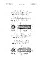
- FIG. 1is a top-plan view of a fusible element according to the present invention
- FIG. 2is a side elevation of the fusible element shown in FIG. 1;
- FIG. 3is a longitudinal section of a fuse including a fusible element as shown in FIGS. 1 and 2;
- FIG. 4is a cross-section of the fuse shown in FIG. 3 along IV--IV of FIG. 3;
- FIG. 5is a modification of the fusible element of FIG. 1 shown in top-plan view
- FIG. 6is a side elevation of the fusible element shown in FIG. 5;
- FIG. 7is a longitudinal section of a fuse including the fusible element shown in FIGS. 5 and 6;
- FIG. 8is a cross-section along VII--VII of the fuse shown in FIG. 7.
- FIGS. 1 to 4numeral 1 has been applied to indicate a tubular casing of electric insulating material, preferably a synthetic resin glass-cloth laminate which is filled with a granular arc-quenching filler 2, e.g. quartz sand.
- a pair of electro-conductive terminal elements 3close the ends of casing 1. Terminal elements 3 may, for instance, be in the shape of caps mounted on the outer ends of casing 1.
- a fusible element generally indicated at 4 embedded in arc-quenching filler 2conductively interconnects said pair of terminal elements. Fusible element 4 includes a relatively long portion 4a of sheet copper having at least one point of reduced cross-section.
- sheet copper portion 4ahas four serially arranged points of reduced cross-section 4a' to generate a relatively high arc voltage upon fusion thereof.
- Fusible element 4further includes at least one relatively short end portion 4b of sheet silver conductively connecting one of said pair of terminal elements 3 and one end of said portion of sheet copper 4a.
- the end portion 4b of sheet silverhas one single point of reduced cross-section 4b.
- the provision of an overlay 5 of an M-effect metalis optional. As generally known in the art, M-effect overlays are used either when it is desired to limit the highest temperature which a fuse may reach, or when it is desired to provide overload protection in addition to short-circuit protection.
- the portions 4a, 4b of the fusible element 4overlap at 6 and are conductively bonded together at the point where they overlap as, for instance, by spot welding.
- the portion of sheet silver 4bis inserted into a slot in a washer 7 of fibrous material, bent a first time 90 deg. at the center of cap 3, then bent a second time 90 deg. about the rim of casing 1 and bent at its end to the outer surface of cap 3.
- the left end of sheet silver portion 4bis spot-welded at 3a to the left terminal cap 3.
- This mode of conductively connecting portion 4b of fusible element 4 to the left cap 3is, however, not the most economical since it requires a relatively long length for silver portion 4b of fusible element 4.
- the length of the silver portion 4b of the fusible element between the end surface of cap 3 and weld 3acan be saved. This can be achieved by the process known as blind soldering which relies on solder in paste form for establishing inaccessible solder joints.
- FIGS. 5 to 8the same reference characters as in FIGS. 1-4 have been applied to designate like parts. It is, therefore, sufficient to describe FIGS. 5 to 8 only to the extent that the structure shown in these figures differs from that shown in FIGS. 1 to 4.
- the center portion 4a of sheet copperhas two end portions 4b of sheet silver.
- the center portion 4a of sheet coppermay have one or several points of reduced cross-section 4a' whose cross-section is relatively large, while each of the end portions 4b of sheet silver has but one single point of reduced cross-section whose cross-section is relatively small.
- the length of center portion 4aexceeds the length of each end portion 4b.
- Portions 4a,4bare spot-welded together at points 6 where they overlap.
- points 4b ' of sheet silver ends 4bwill generate much heat, particularly because they are the points in the fusible element having the smallest cross-section. But since points 4b are so closely positioned to the terminals 3 which, in turn, remain cool because of the fact that they are in contact with a fuse holder having a large heat absorbing and heat dissipating capacity, all the heat generated at points 4b' will readily be dissipated by an axial heat flow toward caps 3 and the fuse holder which is in engagement with caps 3. As a result, the points of reduced cross-section 4b' will have no or very little effect in the load and overload range on the current-carrying capacity of the fusible element and the current rating of the fuse.
- the arc voltage generated at point or points 4b'will keep the arc-current from rising, or rising significantly, during a short while.
- the arc-voltage generated at the point or points 4b'causes a delay in the rise of the current sufficient for the points of reduced cross-section 4a to melt in accordance with the i 2 ⁇ t of points 4a, and the latter to generate the arc-voltage required to bring the fault current rapidly down to zero.
Landscapes
- Fuses (AREA)
Abstract
Description
Claims (3)
Priority Applications (2)
| Application Number | Priority Date | Filing Date | Title |
|---|---|---|---|
| US06/171,558US4308514A (en) | 1980-07-23 | 1980-07-23 | Current-limiting fuse |
| CA000378886ACA1155155A (en) | 1980-07-23 | 1981-06-02 | Current-limiting fuse |
Applications Claiming Priority (1)
| Application Number | Priority Date | Filing Date | Title |
|---|---|---|---|
| US06/171,558US4308514A (en) | 1980-07-23 | 1980-07-23 | Current-limiting fuse |
Publications (1)
| Publication Number | Publication Date |
|---|---|
| US4308514Atrue US4308514A (en) | 1981-12-29 |
Family
ID=22624202
Family Applications (1)
| Application Number | Title | Priority Date | Filing Date |
|---|---|---|---|
| US06/171,558Expired - LifetimeUS4308514A (en) | 1980-07-23 | 1980-07-23 | Current-limiting fuse |
Country Status (2)
| Country | Link |
|---|---|
| US (1) | US4308514A (en) |
| CA (1) | CA1155155A (en) |
Cited By (10)
| Publication number | Priority date | Publication date | Assignee | Title |
|---|---|---|---|---|
| US4488137A (en)* | 1983-08-29 | 1984-12-11 | Commercial Enclosed Fuse Company | Composite fuse links employing dissimilar fusible elements in a series |
| US4547830A (en)* | 1979-09-11 | 1985-10-15 | Rohm Company Limited | Device for protection of a semiconductor device |
| US4731600A (en)* | 1985-12-17 | 1988-03-15 | Brush Fusegear Limited | Fuse |
| US4958426A (en)* | 1987-09-01 | 1990-09-25 | Yazaki Corporation | Fuse terminal manufacturing method |
| US20030156005A1 (en)* | 2002-02-21 | 2003-08-21 | Yazaki Corporation | Fuse and fuse production method |
| US6614340B2 (en)* | 2001-02-13 | 2003-09-02 | Cooper Technologies Company | Full-range high voltage current limiting fuse |
| US20050040926A1 (en)* | 2001-10-03 | 2005-02-24 | Brian Ely | Fuse element and method for making same |
| US20090102594A1 (en)* | 2005-09-23 | 2009-04-23 | William Ogilvie | fuse |
| US20090189730A1 (en)* | 2008-01-30 | 2009-07-30 | Littelfuse, Inc. | Low temperature fuse |
| US20100245028A1 (en)* | 2007-11-08 | 2010-09-30 | Tomoyuki Washizaki | Circuit protective device and method for manufacturing the same |
Citations (1)
| Publication number | Priority date | Publication date | Assignee | Title |
|---|---|---|---|---|
| US2653203A (en)* | 1951-01-30 | 1953-09-22 | Chase Shawmut Co | Current-limiting fuse |
- 1980
- 1980-07-23USUS06/171,558patent/US4308514A/ennot_activeExpired - Lifetime
- 1981
- 1981-06-02CACA000378886Apatent/CA1155155A/ennot_activeExpired
Patent Citations (1)
| Publication number | Priority date | Publication date | Assignee | Title |
|---|---|---|---|---|
| US2653203A (en)* | 1951-01-30 | 1953-09-22 | Chase Shawmut Co | Current-limiting fuse |
Cited By (14)
| Publication number | Priority date | Publication date | Assignee | Title |
|---|---|---|---|---|
| US4547830A (en)* | 1979-09-11 | 1985-10-15 | Rohm Company Limited | Device for protection of a semiconductor device |
| US4488137A (en)* | 1983-08-29 | 1984-12-11 | Commercial Enclosed Fuse Company | Composite fuse links employing dissimilar fusible elements in a series |
| US4731600A (en)* | 1985-12-17 | 1988-03-15 | Brush Fusegear Limited | Fuse |
| AU607687B2 (en)* | 1985-12-17 | 1991-03-14 | Cooper Industries, Inc. | Improved fuse |
| US4958426A (en)* | 1987-09-01 | 1990-09-25 | Yazaki Corporation | Fuse terminal manufacturing method |
| US6614340B2 (en)* | 2001-02-13 | 2003-09-02 | Cooper Technologies Company | Full-range high voltage current limiting fuse |
| US20050040926A1 (en)* | 2001-10-03 | 2005-02-24 | Brian Ely | Fuse element and method for making same |
| US7312688B2 (en)* | 2001-10-03 | 2007-12-25 | Metalor Technologies International S.A. | Fuse element and method for making same |
| US20030156005A1 (en)* | 2002-02-21 | 2003-08-21 | Yazaki Corporation | Fuse and fuse production method |
| US6917277B2 (en)* | 2002-02-21 | 2005-07-12 | Yazaki Corporation | Fuse and fuse production method |
| US20090102594A1 (en)* | 2005-09-23 | 2009-04-23 | William Ogilvie | fuse |
| US20100245028A1 (en)* | 2007-11-08 | 2010-09-30 | Tomoyuki Washizaki | Circuit protective device and method for manufacturing the same |
| US9035740B2 (en)* | 2007-11-08 | 2015-05-19 | Panasonic Intellectual Property Management Co., Ltd. | Circuit protective device and method for manufacturing the same |
| US20090189730A1 (en)* | 2008-01-30 | 2009-07-30 | Littelfuse, Inc. | Low temperature fuse |
Also Published As
| Publication number | Publication date |
|---|---|
| CA1155155A (en) | 1983-10-11 |
Similar Documents
| Publication | Publication Date | Title |
|---|---|---|
| US4216457A (en) | Electric fuse having folded fusible element and heat dams | |
| US3958206A (en) | Chemically augmented electrical fuse | |
| US3529270A (en) | Electric high interrupting capacity fuse for low current ratings | |
| US3705373A (en) | Current limiting fuse | |
| US4308514A (en) | Current-limiting fuse | |
| US4227168A (en) | Fusible element for electric fuses based on a M-effect | |
| US4300281A (en) | Method of making electric fuse having folded fusible element and heat dams | |
| US4388603A (en) | Current limiting fuse | |
| GB2376577A (en) | Time delay fuse | |
| US2827532A (en) | Current-limiting low impedance fuses for small current intensities | |
| US2832868A (en) | Fillerless one-time national electrical code fuses | |
| US2781434A (en) | Current-limiting fuses comprising fuse links of silver and copper | |
| US2688061A (en) | Time lag fuse | |
| US3374328A (en) | Cartridge-type fuse with explosion pots | |
| US4134094A (en) | Fuse element | |
| US2727110A (en) | Time-delay motor protective fuse | |
| US3094600A (en) | Electric fuse having improved cap link connection | |
| US4179677A (en) | Combination of fusible elements for electric fuses | |
| US4028655A (en) | Electrical current limiting fuse with bound sand filler and improved low current fault clearing | |
| US3012121A (en) | Electric fuses | |
| US2018556A (en) | Electric fuse | |
| US4626817A (en) | Current limiting fuse with less inverse time-current characteristic | |
| US3140371A (en) | Fuse constructions | |
| US2879354A (en) | Fusible devices | |
| US2094013A (en) | Expulsion fuse cut-out |
Legal Events
| Date | Code | Title | Description |
|---|---|---|---|
| AS | Assignment | Owner name:GOULD INC., ROLLINGS MEADOWS, IL Free format text:ASSIGNMENT OF ASSIGNORS INTEREST.;ASSIGNOR:KOZACKA FREDERICK J.;REEL/FRAME:003885/0018 Effective date:19810720 Owner name:GOULD INC., ILLINOIS Free format text:ASSIGNMENT OF ASSIGNORS INTEREST;ASSIGNOR:KOZACKA FREDERICK J.;REEL/FRAME:003885/0018 Effective date:19810720 | |
| AS | Assignment | Owner name:GOULD INC., ROLLINGS MEADOWS, ILL. Free format text:ASSIGNMENT OF ASSIGNORS INTEREST.;ASSIGNOR:KOZACKA, FREDERICK J.;REEL/FRAME:003926/0870 Effective date:19811022 | |
| STCF | Information on status: patent grant | Free format text:PATENTED CASE | |
| AS | Assignment | Owner name:GOULD ELECTRONICS INC., OHIO Free format text:ASSIGNMENT OF ASSIGNORS INTEREST;ASSIGNOR:GOULD INC.;REEL/FRAME:006865/0444 Effective date:19940131 | |
| AS | Assignment | Owner name:GA-TEK INC. ( DBA GOULD ELECTRONICS INC.), OHIO Free format text:CHANGE OF NAME;ASSIGNOR:GOULD ELECTRONICS INC.;REEL/FRAME:010033/0876 Effective date:19980101 |