US4306566A - Cholangiogram catheter - Google Patents
Cholangiogram catheterDownload PDFInfo
- Publication number
- US4306566A US4306566AUS06/154,214US15421480AUS4306566AUS 4306566 AUS4306566 AUS 4306566AUS 15421480 AUS15421480 AUS 15421480AUS 4306566 AUS4306566 AUS 4306566A
- Authority
- US
- United States
- Prior art keywords
- tip
- plastic tubing
- shaft
- inches
- conical tip
- Prior art date
- Legal status (The legal status is an assumption and is not a legal conclusion. Google has not performed a legal analysis and makes no representation as to the accuracy of the status listed.)
- Expired - Lifetime
Links
- 239000004033plasticSubstances0.000claimsabstractdescription40
- 229910001220stainless steelInorganic materials0.000claimsabstractdescription14
- 239000010935stainless steelSubstances0.000claimsabstractdescription14
- 210000003462veinAnatomy0.000claimsdescription8
- 230000006698inductionEffects0.000claimsdescription5
- 239000012530fluidSubstances0.000claims1
- 238000000034methodMethods0.000abstractdescription25
- 238000001356surgical procedureMethods0.000abstractdescription9
- 210000003445biliary tractAnatomy0.000abstractdescription3
- 239000002872contrast mediaSubstances0.000abstractdescription3
- 208000001130gallstonesDiseases0.000abstractdescription3
- 238000002347injectionMethods0.000abstract1
- 239000007924injectionSubstances0.000abstract1
- 210000001096cystic ductAnatomy0.000description9
- 238000010276constructionMethods0.000description8
- 238000003780insertionMethods0.000description4
- 230000037431insertionEffects0.000description4
- 230000003213activating effectEffects0.000description3
- 229920001074TenitePolymers0.000description2
- 210000000232gallbladderAnatomy0.000description2
- 239000000463materialSubstances0.000description2
- 241000237858GastropodaSpecies0.000description1
- 210000000683abdominal cavityAnatomy0.000description1
- 210000001367arteryAnatomy0.000description1
- 238000013189cholangiographyMethods0.000description1
- 201000001883cholelithiasisDiseases0.000description1
- 230000000994depressogenic effectEffects0.000description1
- 239000002874hemostatic agentSubstances0.000description1
- 239000007943implantSubstances0.000description1
- 210000004185liverAnatomy0.000description1
- 238000012986modificationMethods0.000description1
- 230000004048modificationEffects0.000description1
- 230000001105regulatory effectEffects0.000description1
- 230000000717retained effectEffects0.000description1
- 238000007789sealingMethods0.000description1
- 238000010998test methodMethods0.000description1
Images
Classifications
- A—HUMAN NECESSITIES
- A61—MEDICAL OR VETERINARY SCIENCE; HYGIENE
- A61M—DEVICES FOR INTRODUCING MEDIA INTO, OR ONTO, THE BODY; DEVICES FOR TRANSDUCING BODY MEDIA OR FOR TAKING MEDIA FROM THE BODY; DEVICES FOR PRODUCING OR ENDING SLEEP OR STUPOR
- A61M25/00—Catheters; Hollow probes
- A61M25/0067—Catheters; Hollow probes characterised by the distal end, e.g. tips
- A61M25/0068—Static characteristics of the catheter tip, e.g. shape, atraumatic tip, curved tip or tip structure
- A61M25/0069—Tip not integral with tube
- A—HUMAN NECESSITIES
- A61—MEDICAL OR VETERINARY SCIENCE; HYGIENE
- A61M—DEVICES FOR INTRODUCING MEDIA INTO, OR ONTO, THE BODY; DEVICES FOR TRANSDUCING BODY MEDIA OR FOR TAKING MEDIA FROM THE BODY; DEVICES FOR PRODUCING OR ENDING SLEEP OR STUPOR
- A61M5/00—Devices for bringing media into the body in a subcutaneous, intra-vascular or intramuscular way; Accessories therefor, e.g. filling or cleaning devices, arm-rests
- A61M5/007—Devices for bringing media into the body in a subcutaneous, intra-vascular or intramuscular way; Accessories therefor, e.g. filling or cleaning devices, arm-rests for contrast media
- A—HUMAN NECESSITIES
- A61—MEDICAL OR VETERINARY SCIENCE; HYGIENE
- A61M—DEVICES FOR INTRODUCING MEDIA INTO, OR ONTO, THE BODY; DEVICES FOR TRANSDUCING BODY MEDIA OR FOR TAKING MEDIA FROM THE BODY; DEVICES FOR PRODUCING OR ENDING SLEEP OR STUPOR
- A61M2210/00—Anatomical parts of the body
- A61M2210/10—Trunk
- A61M2210/1042—Alimentary tract
- A61M2210/1071—Liver; Hepar
- A—HUMAN NECESSITIES
- A61—MEDICAL OR VETERINARY SCIENCE; HYGIENE
- A61M—DEVICES FOR INTRODUCING MEDIA INTO, OR ONTO, THE BODY; DEVICES FOR TRANSDUCING BODY MEDIA OR FOR TAKING MEDIA FROM THE BODY; DEVICES FOR PRODUCING OR ENDING SLEEP OR STUPOR
- A61M2210/00—Anatomical parts of the body
- A61M2210/10—Trunk
- A61M2210/1042—Alimentary tract
- A61M2210/1075—Gall bladder
Definitions
- This inventionpertains to the construction of a tube particularly designed for inserting in a cystic duct utilizing a ligature for closing the duct around the catheter sealing against leakage or induction of air.
- the device of this inventionemploys a stainless steel conical tip securely affixed to the plastic tubing.
- the elongated section of plastic tubinghas a syringe adapter secured to the end of the tubing opposite the conical tip.
- a portion of the method of constructionpertains to an improved device and procedure for securely affixing the conical tip to the tubing.
- Rubber and plastic cathetersare utilized in numerous medical and surgical procedures and have been developed in various configurations, some of which have been patented.
- Plastic or rubber structures having integral tipscreate problems in their gripping by hemostats or forceps in the insertion in that the plastic is deformed and the tips could become detached. This fact prompted your inventor to develop a secure stainless steel tip for transparent tubing creating a structure lending itself to grasping by surgical instruments inserting into a duct and to a secure seal with a ligature encircling the duct adjacent the tip of the catheter.
- a principal object of this inventionwas to construct a catheter particularly suitable for utilization in a cholangiographic procedure producing by x-ray cholangiography.
- the instrument of this inventionis aptly described as a cholangiogram catheter.
- This applicationis designed to apply to the structure of an improved cholangiogram catheter.
- the description of the preferred embodimentwill describe both the device and the machine or method for construction or assembly.
- the device of this inventionpertains to an improved cholangiogram catheter 10 utilizing a stainless steel tip 11 to which is secured a section of plastic tubing 15 which is assembled in a particular configuration creating a ligature gap 16 adjacent the conical tip.
- the space between the flange 17 of conical tip 12 and the plastic tubing 15creates a ligature gap 16 particularly adaptable in the surgical or test procedures for which the cholangiogram catheter 10 of this invention was designed.
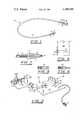
- FIG. 1is a plan, assembled view of the cholangiogram catheter illustrating the device including the stainless steel tip, plastic tubing and the syringe adapter.
- FIG. 2is an enlarged, sectional view of the stainless steel tip with a fragmented section of tubing attached.
- FIG. 3is a perspective view of the machine for practicing a method of assembly of the device of this invention.
- FIG. 4is a partially fragmented view of the pneumatic vise illustrating the vise base and the configuration of the tubing channel and face plate centering guide.
- FIG. 5is a sectional view of a tip die.
- FIG. 6is a sectional view of a cup die.
- Cholangiogram catheter 10is constructed with a stainless steel tip 11.
- Conical tip 12is 1/4" long, whereas the overall length of the stainless steel tip 11 is 3/4".
- the base of the conical tip 12is 91/1000" in diameter and the shaft of the conical tip 12 is 35/1000".
- the shaft 13is approximately 1/2" in length and the aperture 14 projecting through shaft 13 and conical tip 12 is 20/1000".
- the stainless steel tipis press fitted in assembly onto an 18" piece of plastic tubing 15.
- "Tenitea plastic tubing produced by Eastman Kodak Co., was successfully used in the preferred embodiment.
- the plastic tubing 15has an outside diameter of 60/1000" to 65/1000" and an inside diameter of 29/1000" to 30/1000".
- the ligature gap 16is formed between the flange 17 of the conical tip 12 and the flange 18 of plastic tubing 15.
- This ligature gap 16permits the tightening of a ligature around a duct or vein securing the duct or vein into the ligature gap 16 forming a highly satisfactory seal against leakage or induction of air into the duct or vein being subjected to the surgical procedure.
- the cobined action on the duct of the ligature gap 16, the flange 17 of conical tip 12 and the flange 18 of the plastic tubing 15contributes to this improved seal against leakage.
- a syringe adapter 19Secured to the opposite end of plastic tubing 15 is a syringe adapter 19. This structure is sometimes referred to as a blunt needle. This syringe adapter 19 is press fitted into plastic tubing 15 and crimped for maximum securing.
- the assembled device as illustrated in FIG. 1includes the plastic cup 20 receiving a surgical syringe. Secured to the plastic cup 20 is syringe shaft 13 which is formed integral with plastic cup 20 by shaft base 22. In the assembly procedure which will be discussed in detail later in the application, the machine assembling the device creates a tubing crimp 23 adjacent shaft base 22.
- the foregoinggenerally describes the material and construction of the cholangiogram catheter of this invention.
- the device for assembling the components of this inventionis generally described in FIG. 3.
- the devicemay be referred to as a pneumatic press 26 which is supported by mounting base 27 which is constructed of such configuration as to be supported on a table-like structure.
- a portion of the assembly as illustratedcomprises a pneumatic vise 28 which is generally utilized to retain the plastic tubing 15 in the assembly process.
- Pneumatic vise 28is constructed with a vise base 29 and a vise jaw 30.
- the vise base 29 and the vise jaw 30are constructed with a tubing channel 31 having a particular configuration for securely grasping and retaining the plastic tubing 15 in the assembly process.
- the tubing channel 31 at the end through which the extended length of plastic tubing 15 projectshas an inside diameter of 50/1000".
- the diameter of tubing channel 31 adjacent the face plate 32is 65/1000" in diameter to permit some expansion of the plastic tubing 15 in the forced fit assembly process.
- Face plate 32is constructed with a tapered centering cone 33 having a flared configuration for receiving shaft 13 of conical tip 12 in one portion of the assembly process or syringe shaft 21 in another portion of the assembly process.
- pressure regulating valvesare desirable and the pressure under which pneumatic vise 28 operates is normally 110 psi.
- a short distance from the pneumatic vise 28is positioned in an operable relationship pneumatic cylinder 34 which contains a pneumatic piston 35 to which is secured a pneumatic shaft 36 projecting in an operable relationship toward pneumatic vise 28.
- pneumatic shaft 36is constructed with a shaft threaded portion 27 to which is loosely secured a stop nut 38 adapting the pneumatic shaft 36 to receive a tip die 39 which will loosely engage a conical tip 12 with a shaft 13 projecting in the direction of vise 28.
- conical tip 12projects into the tip die 39 and a section of plastic tubing 15 is gripped by pneumatic vise 28, activating pneumatic cylinder 34 by applying approximately 12 psi to the pneumatic piston 35 projecting the shaft 13 through centering cone 33 into tubing channel 31 securely implanting shaft 13 into plastic tubing 15.
- Vise actuating pedal 41is pressed admitting the 110 psi to the vise securely grasping plastic tubing 15 after which piston activating button 42 is depressed admitting 12 psi to the pneumatic piston 35.
- This procedure in its first stepfirmly implants the syringe shaft 21 interior of plastic tubing 15.
- the plastic tubing 15may be projected to a position approximately adjacent the surface of face plate 32 and the vise activating pedal 41 again pressed. This procedure results in a gripping of the plastic tubing 15 adjacent shaft base 22 forming the tubing crimp 23 around syringe shaft 21.
- the characteristic of "Tenite" plastic tubing 15is that it retains this pressure crimp configuration forming a very secure seal on the syringe adapter 19 to plastic tubing 15.
- a typical surgical procedurewould be to open the abdominal cavity to expose the area adjacent the liver and gallbladder. A small incision would be made in the cystic duct. Utilizing the appropriate instrument the cystic duct would be cleared of stones or slugs and the stainless steel tip 11 of the cholangiogram catheters grasped with a hemostat and the tip inserted in the cystic duct. Prior to insertion, the cholangiogram catheter would be attached to the syringe filled with the contrast medium and all of the air expelled from the syringe and the tubing of the cholangiogram catheter. This preliminary procedure is to avoid the introduction of any air into the cystic duct or the biliary tract.
- a ligature or clampis placed around the cystic duct and the cholangiogram catheter is withdrawn slightly bringing the flange 17 adjacent the ligature encircling the cystic duct.
- a tightening of the ligature securing the duct in the ligature gap 16prevents leakage of the contrast medium or induction of air into the cystic duct. No attempt will be made to further describe any operative procedures in that they do not comprise a part of this invention.
- This inventionpertains to the construction and arrangement of an improved cholangiogram catheter and its method of construction or assembly.
Landscapes
- Health & Medical Sciences (AREA)
- Life Sciences & Earth Sciences (AREA)
- Hematology (AREA)
- Anesthesiology (AREA)
- Biomedical Technology (AREA)
- Heart & Thoracic Surgery (AREA)
- Engineering & Computer Science (AREA)
- Animal Behavior & Ethology (AREA)
- General Health & Medical Sciences (AREA)
- Public Health (AREA)
- Veterinary Medicine (AREA)
- Vascular Medicine (AREA)
- Biophysics (AREA)
- Pulmonology (AREA)
- Infusion, Injection, And Reservoir Apparatuses (AREA)
Abstract
Description
This is a continuation of application Ser. No. 913,443, filed June 7, 1978, abandoned.
In surgical procedures it is frequently necessary to insert tubes for injecting contrast mediums into arteries, ducts, and veins preliminary to or as a part of the surgical procedure. In inserting these tubes, hemostats, forceps or other clamp-like structures must be utilized to grip the instrument adjacent the tip for insertion in the vein or duct. Additional steps in the surgical procedure frequently necessitate the closure of the duct around the instrument adjacent the tip. Leakage can occur in this area. Inadvertent induction of air into the procedures hampers the test such as air in the biliary tree can appear on x-rays as a gallstone.
This invention pertains to the construction of a tube particularly designed for inserting in a cystic duct utilizing a ligature for closing the duct around the catheter sealing against leakage or induction of air. The device of this invention employs a stainless steel conical tip securely affixed to the plastic tubing. The elongated section of plastic tubing has a syringe adapter secured to the end of the tubing opposite the conical tip. A portion of the method of construction pertains to an improved device and procedure for securely affixing the conical tip to the tubing.
Catheters are extremely old in the medical field. Rubber and plastic catheters are utilized in numerous medical and surgical procedures and have been developed in various configurations, some of which have been patented. Plastic or rubber structures having integral tips create problems in their gripping by hemostats or forceps in the insertion in that the plastic is deformed and the tips could become detached. This fact prompted your inventor to develop a secure stainless steel tip for transparent tubing creating a structure lending itself to grasping by surgical instruments inserting into a duct and to a secure seal with a ligature encircling the duct adjacent the tip of the catheter.
A principal object of this invention was to construct a catheter particularly suitable for utilization in a cholangiographic procedure producing by x-ray cholangiography. The instrument of this invention is aptly described as a cholangiogram catheter. This application is designed to apply to the structure of an improved cholangiogram catheter. The description of the preferred embodiment will describe both the device and the machine or method for construction or assembly.
The device of this invention pertains to an improvedcholangiogram catheter 10 utilizing a stainless steel tip 11 to which is secured a section ofplastic tubing 15 which is assembled in a particular configuration creating aligature gap 16 adjacent the conical tip. The space between theflange 17 ofconical tip 12 and theplastic tubing 15 creates aligature gap 16 particularly adaptable in the surgical or test procedures for which thecholangiogram catheter 10 of this invention was designed.
For a detailed description of the construction of the device of this invention and the assembly thereof, reference is made to the attached several views wherein identical reference characters will be utilized and refer to identical or equivalent components throughout the several views and the following detailed description of the preferred embodiment.
FIG. 1 is a plan, assembled view of the cholangiogram catheter illustrating the device including the stainless steel tip, plastic tubing and the syringe adapter.
FIG. 2 is an enlarged, sectional view of the stainless steel tip with a fragmented section of tubing attached.
FIG. 3 is a perspective view of the machine for practicing a method of assembly of the device of this invention.
FIG. 4 is a partially fragmented view of the pneumatic vise illustrating the vise base and the configuration of the tubing channel and face plate centering guide.
FIG. 5 is a sectional view of a tip die.
FIG. 6 is a sectional view of a cup die.
For a description of the preferred embodiment, reference is particularly made to FIGS. 1 and 2.Cholangiogram catheter 10 is constructed with a stainless steel tip 11.Conical tip 12 is 1/4" long, whereas the overall length of the stainless steel tip 11 is 3/4". The base of theconical tip 12 is 91/1000" in diameter and the shaft of theconical tip 12 is 35/1000". Theshaft 13 is approximately 1/2" in length and the aperture 14 projecting throughshaft 13 andconical tip 12 is 20/1000". The stainless steel tip is press fitted in assembly onto an 18" piece ofplastic tubing 15. "Tenite", a plastic tubing produced by Eastman Kodak Co., was successfully used in the preferred embodiment. Theplastic tubing 15 has an outside diameter of 60/1000" to 65/1000" and an inside diameter of 29/1000" to 30/1000". In the final assembly of this device, theligature gap 16 is formed between theflange 17 of theconical tip 12 and theflange 18 ofplastic tubing 15. Thisligature gap 16 permits the tightening of a ligature around a duct or vein securing the duct or vein into theligature gap 16 forming a highly satisfactory seal against leakage or induction of air into the duct or vein being subjected to the surgical procedure. The cobined action on the duct of theligature gap 16, theflange 17 ofconical tip 12 and theflange 18 of theplastic tubing 15 contributes to this improved seal against leakage. Secured to the opposite end ofplastic tubing 15 is asyringe adapter 19. This structure is sometimes referred to as a blunt needle. Thissyringe adapter 19 is press fitted intoplastic tubing 15 and crimped for maximum securing. The assembled device as illustrated in FIG. 1 includes theplastic cup 20 receiving a surgical syringe. Secured to theplastic cup 20 issyringe shaft 13 which is formed integral withplastic cup 20 byshaft base 22. In the assembly procedure which will be discussed in detail later in the application, the machine assembling the device creates atubing crimp 23adjacent shaft base 22. The foregoing generally describes the material and construction of the cholangiogram catheter of this invention.
The device for assembling the components of this invention is generally described in FIG. 3. The device may be referred to as apneumatic press 26 which is supported bymounting base 27 which is constructed of such configuration as to be supported on a table-like structure. A portion of the assembly as illustrated comprises apneumatic vise 28 which is generally utilized to retain theplastic tubing 15 in the assembly process.Pneumatic vise 28 is constructed with avise base 29 and avise jaw 30. Thevise base 29 and thevise jaw 30 are constructed with atubing channel 31 having a particular configuration for securely grasping and retaining theplastic tubing 15 in the assembly process. Thetubing channel 31 at the end through which the extended length ofplastic tubing 15 projects has an inside diameter of 50/1000". The diameter oftubing channel 31 adjacent theface plate 32 is 65/1000" in diameter to permit some expansion of theplastic tubing 15 in the forced fit assembly process.Face plate 32 is constructed with a tapered centeringcone 33 having a flared configuration for receivingshaft 13 ofconical tip 12 in one portion of the assembly process orsyringe shaft 21 in another portion of the assembly process. In operation of the device, pressure regulating valves are desirable and the pressure under whichpneumatic vise 28 operates is normally 110 psi. A short distance from thepneumatic vise 28 is positioned in an operable relationshippneumatic cylinder 34 which contains apneumatic piston 35 to which is secured apneumatic shaft 36 projecting in an operable relationship towardpneumatic vise 28. The end ofpneumatic shaft 36 is constructed with a shaft threadedportion 27 to which is loosely secured astop nut 38 adapting thepneumatic shaft 36 to receive atip die 39 which will loosely engage aconical tip 12 with ashaft 13 projecting in the direction ofvise 28. In the process for attaching a stainless steel tip 11 to theplastic tubing 15,conical tip 12 projects into thetip die 39 and a section ofplastic tubing 15 is gripped bypneumatic vise 28, activatingpneumatic cylinder 34 by applying approximately 12 psi to thepneumatic piston 35 projecting theshaft 13 through centeringcone 33 intotubing channel 31 securely implantingshaft 13 intoplastic tubing 15. This assembly process results in the leaving or forming of theligature gap 16 adjacent theflange 17 ofcone 12 and theflange 18 oftubing 15. A similar procedure is utilized in attaching thesyringe adapter 19 to the opposite end ofplastic tubing 15. A different adapter must be secured to thepneumatic shaft 36. An adapter designed to fit into thesyringe adapter 19 is secured to the shaft threadedportion 37 and affixed by rotation ofstop nut 38. Cup die 40 projects intosyringe adapter 19 and the section ofplastic tubing 15 is retained inpneumatic vise 28.Vise actuating pedal 41 is pressed admitting the 110 psi to the vise securely graspingplastic tubing 15 after whichpiston activating button 42 is depressed admitting 12 psi to thepneumatic piston 35. This procedure in its first step firmly implants thesyringe shaft 21 interior ofplastic tubing 15. After this initial step, theplastic tubing 15 may be projected to a position approximately adjacent the surface offace plate 32 and thevise activating pedal 41 again pressed. This procedure results in a gripping of theplastic tubing 15adjacent shaft base 22 forming thetubing crimp 23 aroundsyringe shaft 21. The characteristic of "Tenite"plastic tubing 15 is that it retains this pressure crimp configuration forming a very secure seal on thesyringe adapter 19 toplastic tubing 15.
In exploratory or gallbladder surgery, a typical surgical procedure would be to open the abdominal cavity to expose the area adjacent the liver and gallbladder. A small incision would be made in the cystic duct. Utilizing the appropriate instrument the cystic duct would be cleared of stones or slugs and the stainless steel tip 11 of the cholangiogram catheters grasped with a hemostat and the tip inserted in the cystic duct. Prior to insertion, the cholangiogram catheter would be attached to the syringe filled with the contrast medium and all of the air expelled from the syringe and the tubing of the cholangiogram catheter. This preliminary procedure is to avoid the introduction of any air into the cystic duct or the biliary tract. Air on x-rays can confuse the test by indicating or obscuring gallstones. After insertion of the stainless steel tip 11 into the cystic duct, a ligature or clamp is placed around the cystic duct and the cholangiogram catheter is withdrawn slightly bringing theflange 17 adjacent the ligature encircling the cystic duct. A tightening of the ligature securing the duct in theligature gap 16 prevents leakage of the contrast medium or induction of air into the cystic duct. No attempt will be made to further describe any operative procedures in that they do not comprise a part of this invention. This invention pertains to the construction and arrangement of an improved cholangiogram catheter and its method of construction or assembly.
Having described in detail the components of this invention including dimensions and preferred materials, together with a device for assembling the improved cholangiogram catheter, what is desired to be claimed are all modifications of the device or methods for assembly not departing from the scope of equivalents of the device and method of assembly as defined in the appended claims.
Claims (1)
1. A cholangiogram catheter comprising:
an elongated stainless steel tip having an overall length of about 0.75 inches;
said stainless steel tip having a conical tip portion with a base diameter of about 0.091 inches and terminating in a point and a cylindrical flange at the base of said conical tip;
a cylindrical shaft about 0.5 inches long having a diameter of about 0.035 inches projecting from the center of said cylindrical flange;
a central passageway having a diameter of about 0.020 inches extending through said tip and said shaft and opening at the point at the first end of the conical tip portion for flowing fluid through the passageway;
stable semi-rigid plastic tubing having an outside diameter of 0.060 to 0.065 inches and an inside diameter of 0.029 to 0.030 inches encasing and securely attached at a first end to said shaft of said tip;
a space provided along said shaft between said flange at the base of said conical tip and the said first end of said plastic tubing;
the spaced portion between said flange and said plastic tubing forming a ligature gap on said shaft adjacent said flange to permit tightening of a ligature around a duct or vein securing the duct or vein into the ligature gap to form a satisfactory seal against leakage or induction of air into the vein or duct; and
a syringe adapter including a shaft attached to a second end of said plastic tubing.
Priority Applications (1)
| Application Number | Priority Date | Filing Date | Title |
|---|---|---|---|
| US06/154,214US4306566A (en) | 1978-06-07 | 1980-05-29 | Cholangiogram catheter |
Applications Claiming Priority (2)
| Application Number | Priority Date | Filing Date | Title |
|---|---|---|---|
| US91344378A | 1978-06-07 | 1978-06-07 | |
| US06/154,214US4306566A (en) | 1978-06-07 | 1980-05-29 | Cholangiogram catheter |
Related Parent Applications (1)
| Application Number | Title | Priority Date | Filing Date |
|---|---|---|---|
| US91344378AContinuation | 1978-06-07 | 1978-06-07 |
Publications (1)
| Publication Number | Publication Date |
|---|---|
| US4306566Atrue US4306566A (en) | 1981-12-22 |
Family
ID=26851252
Family Applications (1)
| Application Number | Title | Priority Date | Filing Date |
|---|---|---|---|
| US06/154,214Expired - LifetimeUS4306566A (en) | 1978-06-07 | 1980-05-29 | Cholangiogram catheter |
Country Status (1)
| Country | Link |
|---|---|
| US (1) | US4306566A (en) |
Cited By (27)
| Publication number | Priority date | Publication date | Assignee | Title |
|---|---|---|---|---|
| US4368737A (en)* | 1980-07-07 | 1983-01-18 | Purdue Research Foundation | Implantable catheter |
| US4664659A (en)* | 1982-03-12 | 1987-05-12 | Terumo Kabushiki Kaisha | Medical device and method for manufacturing the same |
| US5071412A (en)* | 1991-03-01 | 1991-12-10 | Laparomed Corporation | Device and method for performing cholangiography |
| EP0437542A4 (en)* | 1988-10-07 | 1992-02-05 | Michel H Hayman | Apparatus for in situ radiotherapy |
| US5146925A (en)* | 1990-11-21 | 1992-09-15 | Lamar Snow | Cholangiocatheter and delivery system |
| EP0515007A1 (en)* | 1991-05-20 | 1992-11-25 | The Kendall Company | Tunnelled epidural catheter |
| WO1992021398A1 (en)* | 1991-06-07 | 1992-12-10 | Taut, Incorporated | Uncollapsible catheter and methods |
| US5183470A (en)* | 1991-03-04 | 1993-02-02 | International Medical, Inc. | Laparoscopic cholangiogram catheter and method of using same |
| US5246430A (en)* | 1992-03-27 | 1993-09-21 | Taut, Inc. | Reinforced cholangiogram catheter |
| US5303714A (en)* | 1990-11-09 | 1994-04-19 | Boston Scientific Corporation | Guidewire for crossing occlusions in blood vessels |
| WO1994014488A1 (en)* | 1992-12-24 | 1994-07-07 | Miguel Angel Gramajo Booth | Dosing apparatus producing an aspiration-impellent action applicable to phlebology and other medical applications |
| US5605539A (en)* | 1992-09-11 | 1997-02-25 | Urohealth Systems, Inc. | Self-introducing infusion catheter |
| US5716321A (en)* | 1995-10-10 | 1998-02-10 | Conceptus, Inc. | Method for maintaining separation between a falloposcope and a tubal wall |
| US5730733A (en)* | 1995-06-01 | 1998-03-24 | Scimed Life Systems, Inc. | Flow assisted catheter |
| US5899892A (en)* | 1996-05-31 | 1999-05-04 | Scimed Life Systems, Inc. | Catheter having distal fiber braid |
| US6193705B1 (en) | 1998-10-28 | 2001-02-27 | Scimed Life Systems, Inc. | Flow assisted catheter |
| US6673025B1 (en) | 1993-12-01 | 2004-01-06 | Advanced Cardiovascular Systems, Inc. | Polymer coated guidewire |
| US20070249964A1 (en)* | 1997-06-04 | 2007-10-25 | Advanced Cardiovascular Systems, Inc. | Polymer coated guide wire |
| US20080103483A1 (en)* | 2006-10-30 | 2008-05-01 | Johnson Benjamin A | Infusion catheter with composite tip |
| US7494474B2 (en) | 1997-06-04 | 2009-02-24 | Advanced Cardiovascular Systems, Inc. | Polymer coated guidewire |
| US20090143764A1 (en)* | 2007-11-30 | 2009-06-04 | Medtronic, Inc. | Infusion catheter assembly with reduced backflow |
| US7704245B2 (en) | 2003-04-14 | 2010-04-27 | Cook Incorporated | Large diameter delivery catheter/sheath |
| US20100198319A1 (en)* | 2007-07-04 | 2010-08-05 | Arad Eliahu | System and method for manipulating a temperature of a patient |
| US20100312226A1 (en)* | 2009-06-03 | 2010-12-09 | John Anderson Armistead | Barb-ended, self-actuating, partially indwelling and continually retained urinary catheter |
| US11000670B2 (en) | 2003-04-28 | 2021-05-11 | Cook Medical Technologies Llc | Flexible sheath with varying durometer |
| US11452533B2 (en) | 2019-01-10 | 2022-09-27 | Abbott Cardiovascular Systems Inc. | Guide wire tip having roughened surface |
| WO2024033359A1 (en)* | 2022-08-09 | 2024-02-15 | Biotronik Ag | Dilator tip design for enhanced force transmission |
Citations (8)
| Publication number | Priority date | Publication date | Assignee | Title |
|---|---|---|---|---|
| US504424A (en)* | 1893-09-05 | Oscar de pezzer | ||
| US1045326A (en)* | 1912-04-30 | 1912-11-26 | Charles A Ruflin | Irrigating-catheter. |
| US1888349A (en)* | 1932-02-15 | 1932-11-22 | Charles M Jacoby | Catheter |
| US2976865A (en)* | 1958-10-21 | 1961-03-28 | Shipley Richard Edwin | Cylindrical strain gauge |
| US3958557A (en)* | 1975-03-10 | 1976-05-25 | Texas Medical Products, Inc. | Coronary artery bypass graft testing device and method |
| US4116227A (en)* | 1976-06-28 | 1978-09-26 | Plasco, Inc. | Combination catheter venting and urine sample collecting unit and method of making the same |
| US4122858A (en)* | 1977-03-23 | 1978-10-31 | Peter Schiff | Adapter for intra-aortic balloons and the like |
| US4173228A (en)* | 1977-05-16 | 1979-11-06 | Applied Medical Devices | Catheter locating device |
- 1980
- 1980-05-29USUS06/154,214patent/US4306566A/ennot_activeExpired - Lifetime
Patent Citations (8)
| Publication number | Priority date | Publication date | Assignee | Title |
|---|---|---|---|---|
| US504424A (en)* | 1893-09-05 | Oscar de pezzer | ||
| US1045326A (en)* | 1912-04-30 | 1912-11-26 | Charles A Ruflin | Irrigating-catheter. |
| US1888349A (en)* | 1932-02-15 | 1932-11-22 | Charles M Jacoby | Catheter |
| US2976865A (en)* | 1958-10-21 | 1961-03-28 | Shipley Richard Edwin | Cylindrical strain gauge |
| US3958557A (en)* | 1975-03-10 | 1976-05-25 | Texas Medical Products, Inc. | Coronary artery bypass graft testing device and method |
| US4116227A (en)* | 1976-06-28 | 1978-09-26 | Plasco, Inc. | Combination catheter venting and urine sample collecting unit and method of making the same |
| US4122858A (en)* | 1977-03-23 | 1978-10-31 | Peter Schiff | Adapter for intra-aortic balloons and the like |
| US4173228A (en)* | 1977-05-16 | 1979-11-06 | Applied Medical Devices | Catheter locating device |
Cited By (45)
| Publication number | Priority date | Publication date | Assignee | Title |
|---|---|---|---|---|
| US4368737A (en)* | 1980-07-07 | 1983-01-18 | Purdue Research Foundation | Implantable catheter |
| US4664659A (en)* | 1982-03-12 | 1987-05-12 | Terumo Kabushiki Kaisha | Medical device and method for manufacturing the same |
| EP0437542A4 (en)* | 1988-10-07 | 1992-02-05 | Michel H Hayman | Apparatus for in situ radiotherapy |
| US5303714A (en)* | 1990-11-09 | 1994-04-19 | Boston Scientific Corporation | Guidewire for crossing occlusions in blood vessels |
| US5385152A (en)* | 1990-11-09 | 1995-01-31 | Boston Scientific Corporation | Guidewire for crossing occlusions in blood vessels |
| US5146925A (en)* | 1990-11-21 | 1992-09-15 | Lamar Snow | Cholangiocatheter and delivery system |
| US5071412A (en)* | 1991-03-01 | 1991-12-10 | Laparomed Corporation | Device and method for performing cholangiography |
| US5183470A (en)* | 1991-03-04 | 1993-02-02 | International Medical, Inc. | Laparoscopic cholangiogram catheter and method of using same |
| EP0515007A1 (en)* | 1991-05-20 | 1992-11-25 | The Kendall Company | Tunnelled epidural catheter |
| WO1992021398A1 (en)* | 1991-06-07 | 1992-12-10 | Taut, Incorporated | Uncollapsible catheter and methods |
| US5246430A (en)* | 1992-03-27 | 1993-09-21 | Taut, Inc. | Reinforced cholangiogram catheter |
| US5605539A (en)* | 1992-09-11 | 1997-02-25 | Urohealth Systems, Inc. | Self-introducing infusion catheter |
| WO1994014488A1 (en)* | 1992-12-24 | 1994-07-07 | Miguel Angel Gramajo Booth | Dosing apparatus producing an aspiration-impellent action applicable to phlebology and other medical applications |
| US6673025B1 (en) | 1993-12-01 | 2004-01-06 | Advanced Cardiovascular Systems, Inc. | Polymer coated guidewire |
| US5947939A (en)* | 1995-06-01 | 1999-09-07 | Scimed Life Systems, Inc. | Flow assisted catheter |
| US5730733A (en)* | 1995-06-01 | 1998-03-24 | Scimed Life Systems, Inc. | Flow assisted catheter |
| US5716321A (en)* | 1995-10-10 | 1998-02-10 | Conceptus, Inc. | Method for maintaining separation between a falloposcope and a tubal wall |
| US5873815A (en)* | 1995-10-10 | 1999-02-23 | Conceptus, Inc. | Access catheter and method for maintaining separation between a falloposcope and a tubal wall |
| US5935056A (en)* | 1995-10-10 | 1999-08-10 | Conceptus, Inc. | Access catheter and method for maintaining separation between a falloposcope and a tubal wall |
| US6196966B1 (en) | 1995-10-10 | 2001-03-06 | Conceptus, Inc. | Access catheter and method for maintaining separation between a falloposcope and a tubal wall |
| US5899892A (en)* | 1996-05-31 | 1999-05-04 | Scimed Life Systems, Inc. | Catheter having distal fiber braid |
| US5961511A (en)* | 1996-05-31 | 1999-10-05 | Scimed Life Systems, Inc. | Catheter having LCP reinforced distal portion |
| US7494474B2 (en) | 1997-06-04 | 2009-02-24 | Advanced Cardiovascular Systems, Inc. | Polymer coated guidewire |
| US7455646B2 (en) | 1997-06-04 | 2008-11-25 | Advanced Cardiovascular Systems, Inc. | Polymer coated guide wire |
| US20070249964A1 (en)* | 1997-06-04 | 2007-10-25 | Advanced Cardiovascular Systems, Inc. | Polymer coated guide wire |
| US6193705B1 (en) | 1998-10-28 | 2001-02-27 | Scimed Life Systems, Inc. | Flow assisted catheter |
| US7968038B2 (en) | 2003-04-14 | 2011-06-28 | Cook Medical Technologies Llc | Large diameter delivery catheter/sheath |
| US7704245B2 (en) | 2003-04-14 | 2010-04-27 | Cook Incorporated | Large diameter delivery catheter/sheath |
| US11000670B2 (en) | 2003-04-28 | 2021-05-11 | Cook Medical Technologies Llc | Flexible sheath with varying durometer |
| US20110238040A1 (en)* | 2006-10-30 | 2011-09-29 | Medtronic, Inc. | Infusion catheter with composite tip |
| US20080103456A1 (en)* | 2006-10-30 | 2008-05-01 | Johnson Benjamin A | Infusion catheter |
| WO2008054700A3 (en)* | 2006-10-30 | 2008-12-04 | Medtronic Inc | Infusion catheters |
| US8945089B2 (en) | 2006-10-30 | 2015-02-03 | Medtronic, Inc. | Infusion catheter with composite tip |
| US20080103483A1 (en)* | 2006-10-30 | 2008-05-01 | Johnson Benjamin A | Infusion catheter with composite tip |
| US7976530B2 (en) | 2006-10-30 | 2011-07-12 | Medtronic, Inc. | Infusion catheter with composite tip |
| US20100198319A1 (en)* | 2007-07-04 | 2010-08-05 | Arad Eliahu | System and method for manipulating a temperature of a patient |
| US8361132B2 (en)* | 2007-07-04 | 2013-01-29 | Biotempero Ltd. | System and method for manipulating a temperature of a patient |
| US8480626B2 (en) | 2007-11-30 | 2013-07-09 | Medtronic, Inc. | Infusion catheter assembly with reduced backflow |
| US8876774B2 (en) | 2007-11-30 | 2014-11-04 | Medtronic, Inc. | Infusion catheter assembly with reduced backflow |
| US20090143764A1 (en)* | 2007-11-30 | 2009-06-04 | Medtronic, Inc. | Infusion catheter assembly with reduced backflow |
| US8096986B2 (en)* | 2009-06-03 | 2012-01-17 | John Anderson Armistead | Barb-ended, self-actuating, partially indwelling and continually retained urinary catheter |
| US20100312226A1 (en)* | 2009-06-03 | 2010-12-09 | John Anderson Armistead | Barb-ended, self-actuating, partially indwelling and continually retained urinary catheter |
| US11452533B2 (en) | 2019-01-10 | 2022-09-27 | Abbott Cardiovascular Systems Inc. | Guide wire tip having roughened surface |
| US12137923B2 (en) | 2019-01-10 | 2024-11-12 | Abbott Cardiovascular Systems Inc. | Guide wire tip having roughened surface |
| WO2024033359A1 (en)* | 2022-08-09 | 2024-02-15 | Biotronik Ag | Dilator tip design for enhanced force transmission |
Similar Documents
| Publication | Publication Date | Title |
|---|---|---|
| US4306566A (en) | Cholangiogram catheter | |
| US4817631A (en) | Method for removing tissue from a body | |
| US11224440B2 (en) | Release device for medical tissue clips | |
| US7217277B2 (en) | Device for providing intracardiac access in an open chest | |
| US4263917A (en) | Method of sealing bile duct during cholangiography | |
| US4449532A (en) | Dilator to facilitate endoscope insertion into the body | |
| US4713057A (en) | Mechanical assist device for inserting catheters | |
| EP1113837B1 (en) | Catheter introducer with clamping wings | |
| US4813928A (en) | Nozzle for tissue adhesive | |
| US5741234A (en) | Anatomical cavity access sealing condit | |
| US5755727A (en) | Method device for locating and sealing a blood vessel | |
| US5366446A (en) | Introducer assembly | |
| US5312362A (en) | Seal for a cannula assembly | |
| US8403891B2 (en) | Method for centering a valve | |
| US5704925A (en) | Medical instrument for injecting liquids into a hollow organ and/or drawing off liquids from a hollow organ, in particular a bile duct | |
| JPH05137792A (en) | Medical access-sheathing device | |
| JPH04263870A (en) | Medical apparatus and endermic arrange- ment thereof in body cavity | |
| WO1985000009A1 (en) | Method and device to perforate, in particular to puncture a membranous member while utilizing vacuum fixation | |
| JPS6185934A (en) | Surgical instrument for forming skin opening part | |
| JPH02147072A (en) | Medical inserting and guide means | |
| CA2066354A1 (en) | Cannula | |
| US20040039306A1 (en) | Crimp and cut tool for sealing and unsealing guide wires and tubular instruments | |
| US20020068911A1 (en) | Removable protective cannula for use in surgery | |
| JP3126077B2 (en) | Trocar | |
| US11134983B1 (en) | Obturator and cannula for uterine and fetal surgeries |
Legal Events
| Date | Code | Title | Description |
|---|---|---|---|
| AS | Assignment | Owner name:GESCO INTERNATIONAL, INC., A TX CORP. Free format text:ASSIGNMENT OF ASSIGNORS INTEREST.;ASSIGNOR:SINKO, GEORGE E.;REEL/FRAME:003909/0339 Effective date:19810915 Owner name:GESCO INTERNATIONAL, INC., A TX CORP., TEXAS Free format text:ASSIGNMENT OF ASSIGNORS INTEREST;ASSIGNOR:SINKO, GEORGE E.;REEL/FRAME:003909/0339 Effective date:19810915 | |
| STCF | Information on status: patent grant | Free format text:PATENTED CASE | |
| AS | Assignment | Owner name:MEDCHEM PRODUCTS, INC., MASSACHUSETTS Free format text:ASSIGNMENT OF ASSIGNORS INTEREST.;ASSIGNOR:GESCO INTERNATIONAL, INC., A TX CORP.;REEL/FRAME:006223/0216 Effective date:19920806 | |
| AS | Assignment | Owner name:FLEET BANK OF MASSACHUSETTS, N.A. Free format text:SECURITY INTEREST;ASSIGNOR:MEDCHEM PRODUCTS, INC. A MA CORP.;REEL/FRAME:006258/0554 Effective date:19920731 |