US4305388A - Automatic inhalation temperature control - Google Patents
Automatic inhalation temperature controlDownload PDFInfo
- Publication number
- US4305388A US4305388AUS06/193,838US19383880AUS4305388AUS 4305388 AUS4305388 AUS 4305388AUS 19383880 AUS19383880 AUS 19383880AUS 4305388 AUS4305388 AUS 4305388A
- Authority
- US
- United States
- Prior art keywords
- temperature
- inhalation
- gas
- exhalation
- body core
- Prior art date
- Legal status (The legal status is an assumption and is not a legal conclusion. Google has not performed a legal analysis and makes no representation as to the accuracy of the status listed.)
- Expired - Lifetime
Links
- 230000036760body temperatureEffects0.000claimsabstractdescription20
- 238000000926separation methodMethods0.000claimsabstractdescription13
- 230000001105regulatory effectEffects0.000claimsdescription9
- 230000004044responseEffects0.000claimsdescription5
- 230000001276controlling effectEffects0.000claimsdescription4
- 238000000034methodMethods0.000claimsdescription4
- 238000010438heat treatmentMethods0.000claimsdescription3
- 230000007257malfunctionEffects0.000claimsdescription3
- 238000005259measurementMethods0.000claimsdescription2
- 230000029058respiratory gaseous exchangeEffects0.000claimsdescription2
- 238000001514detection methodMethods0.000claims1
- 230000000241respiratory effectEffects0.000claims1
- 238000002560therapeutic procedureMethods0.000abstractdescription3
- 206010002091AnaesthesiaDiseases0.000description3
- 230000037005anaesthesiaEffects0.000description3
- 230000000694effectsEffects0.000description3
- 239000000523sampleSubstances0.000description3
- 238000002627tracheal intubationMethods0.000description3
- 238000010586diagramMethods0.000description2
- 238000001356surgical procedureMethods0.000description2
- 230000010485copingEffects0.000description1
- 238000006073displacement reactionMethods0.000description1
- 230000008642heat stressEffects0.000description1
- 238000011084recoveryMethods0.000description1
- 210000002345respiratory systemAnatomy0.000description1
- 230000002269spontaneous effectEffects0.000description1
- 238000010792warmingMethods0.000description1
Images
Classifications
- A—HUMAN NECESSITIES
- A61—MEDICAL OR VETERINARY SCIENCE; HYGIENE
- A61M—DEVICES FOR INTRODUCING MEDIA INTO, OR ONTO, THE BODY; DEVICES FOR TRANSDUCING BODY MEDIA OR FOR TAKING MEDIA FROM THE BODY; DEVICES FOR PRODUCING OR ENDING SLEEP OR STUPOR
- A61M16/00—Devices for influencing the respiratory system of patients by gas treatment, e.g. ventilators; Tracheal tubes
- A61M16/10—Preparation of respiratory gases or vapours
- A61M16/1075—Preparation of respiratory gases or vapours by influencing the temperature
- A—HUMAN NECESSITIES
- A61—MEDICAL OR VETERINARY SCIENCE; HYGIENE
- A61M—DEVICES FOR INTRODUCING MEDIA INTO, OR ONTO, THE BODY; DEVICES FOR TRANSDUCING BODY MEDIA OR FOR TAKING MEDIA FROM THE BODY; DEVICES FOR PRODUCING OR ENDING SLEEP OR STUPOR
- A61M2205/00—General characteristics of the apparatus
- A61M2205/33—Controlling, regulating or measuring
- A61M2205/3368—Temperature
- A—HUMAN NECESSITIES
- A61—MEDICAL OR VETERINARY SCIENCE; HYGIENE
- A61M—DEVICES FOR INTRODUCING MEDIA INTO, OR ONTO, THE BODY; DEVICES FOR TRANSDUCING BODY MEDIA OR FOR TAKING MEDIA FROM THE BODY; DEVICES FOR PRODUCING OR ENDING SLEEP OR STUPOR
- A61M2230/00—Measuring parameters of the user
- A61M2230/50—Temperature
Definitions
- This inventionrelates generally to a ventilator therapy apparatus and method utilizing an inhalation heater and is an improvement over the system disclosed in my prior copending application, Ser. No. 89,320 filed Oct. 30, 1979 now U.S. Pat. No. 4,248,217, with respect to which the present application is a continuation-in-part.
- a plural mode type of control system for an inhalation heateris operative only in its tracking mode to so regulate the temperature of the inspired air to track below the temperature of the expired air by a substantially constant amount.
- the objective of such trackingwas to prevent the patient from absorbing heat through the respiratory system in excess amounts that may cause heat stress.
- temperature sensorswere provided for measuring the temperature of both the inspired gas and the expired gas without any direct measurement of body core temperature.
- the inspired gas temperatureis tracked only below the expired gas temperature by a substantially constant amount. The foregoing system was based on the heating of the gas by the body after it is inhaled under control of the body's temperature regulating system.
- an important object of the present inventionto provide an improved heater control system for inhalation heaters through which the patient's body temperature may be substantially maintained at a desired level determined by the anesthesiologist despite any malfunction of the body temperature regulatory system of the patient.
- the inhalation heater control systemis modified by the addition of a body temperature probe and temperature measuring circuit to sense the body core temperature in order to effect automatic switching between tracking below the expired gas temperature and tracking above the expired gas temperature in response to deviation from a desired body temperature.
- a logic control componenttherefore receives a temperature signal from a body core temperature measuring component to supply switching signals to an adjustment circuit from which an input is applied to an adjustable comparator to which a second input is applied from the inspired and expired gas temperature sensors in the automatic tracking mode of operation.
- the heater controlling signal output of the comparatorwill thereby produce an output signal controlling operation of the inhalation heater as a tracking function of the temperature of the expired gas causing the inspired gas temperature to track below the expired gas temperature by a constant separation amount such as 1° C. or track above the expired gas temperature by another substantially constant separation amount such as 3° C. Automatic switching between such negative and positive tracking functions occurs when the body core temperature drops below or rises above a desired body temperature preset through the body core temperature measuring component. The system will thereby maintain the patient's body core temperature close to the desired level by delivering a controlled amount of heat to the patient through the inhalation heater.
- the foregoing automatic switching mode of operationmay be effected in a separate operational mode of the inhalation heater control system disclosed in my prior copending application aforementioned, by the addition of the body core temperature measuring component, the logic control switch and the track separation adjustment circuit through which temperature tracking separation may be adjusted for tracking below and above the expired gas temperature.
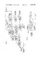
- FIG. 1is a schematic block diagram illustrating the system of the present invention.
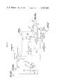
- FIG. 2is an electrical circuit diagram showing the improved features of the control system in greater detail.
- FIG. 3is a graphical illustration of the operational characteristics associated with the improved system of the present invention.
- FIG. 1illustrates a heater control system for an inhalation gas heater 7 associated with a ventilator 5 through which ventilator therapy may be applied to a patient as generally disclosed in my prior copending application aforementioned.
- inhaled or inspired gasis conducted through the ventilator 5 to the patient along an inhalation path 4 and through an intubation coupler 9.
- the intubation coupleris connected to the intubation tube installed within a patient as disclosed in detail in my prior copending application aforementioned.
- Expired gasis conducted through the coupler 9 to an exhalation path 3.
- the temperature of the inhaled and exhaled gasis monitored through gas probes 11 and 14 respectfully connected to temperature sensors 16 and 18 which may be of the electronic thermometer types.
- the output of the inhalation temperature sensor 16is fed to one input of adjustable comparator 36, while the output of the exhalation temperature sensor 18 is fed to the other input of the adjustable comparator 36 through a mode selector component 20.
- the signal output of the comparator 36is fed through a heater drive circuit 38 isolating the low voltage control portion of the system from a power supply 40.
- the power fed from the power supply 40 to the inhalation gas heater 7 for energization thereofwill be controlled by the signal received from the comparator 36.
- the systemmay be operated in a set temperature mode.
- the systemis, however, modified within the mode selector component 20 and by the addition of a logic control switch component 50 receiving an input from the output of a generally well known body core temperature measuring component 52 which includes a body probe 54 connected to a temperature sensor 56, the output of which is fed to one input of a comparator 58, the other input of the comparator being connected to a temperature reference 60.
- the output of the comparator 58supplies the aforementioned input signal to the logic control switch component 50 in order to effect automatic switching when the body temperature deviates from a desired body temperature level determined through the temperature reference 60.
- the signal output of the logic control component 50operates on the track separation adjustment circuit 46 to change the voltage level applied to the input 44 of the adjustable comparator 36.
- the control logicselects a track separation through the adjustment circuit 46 to cause the inspired gas to track along curve portion 72, 1° C. below the expired gas temperature denoted by curve 62. If the body temperature drops below the desired value again, the control logic will select the 3° C. track separation condition as denoted by curve portion 74 to again force the body temperature up toward the desired value.
- the expired gas temperature as denoted by curve 62 in FIG. 3thus provides a reference tracked by the inspired gas temperature along curve portions 72 and 74 which cross curve 62 at separation switching points 66, 68 and 70 in FIG. 3.
- FIG. 2illustrates in greater detail certain portions of the heater control circuit, which is otherwise generally similar to that disclosed in my prior copending application aforementioned.
- the heater control systemis switched to the various operational modes are previously described in my prior copending application aforementioned by displacement of the switch sections 76 and 78 of the mode selector component 20 between its operative positions engaging the various mode contacts.
- the automatic switching mode of operationis effected when the contactors of the switch sections 76 and 78 engage the contacts 80 and 82.
- contact 80is engaged, the exhalation temperature signal output of the temperature sensor 18 is fed to the input 42 of the comparator 36.
- normal negative tracking operationoccurs as described in my prior copending application aforementioned.
- the switch section 78engages a contact 82 which is connected to the logic control switch component 50. Accordingly, voltage is applied through contact 82 to one terminal of relay coil 84 in the logic control switch component, the other terminal of which is connected to the collector of a signal transistor 86 having an input base to which a signal input is applied from the output of the body core temperature component 52.
- the low voltage source connected to the switch section 78applies appropriate voltages to the interconnected terminals of the relay coil 84 and collector of transistor 86 in order to maintain the relay coil in one state when the body core temperature signal reflects a body temperature above the desired temperature level and in another operational state when the body core temperature is below the desired temperature level.
- the signal transistor 86When the body core temperature is above the desired level, the signal transistor 86 will be switched off and any back EMF from relay coil 84 is absorbed by diode 88. With the relay coil 84 thereby deenergized, its relay switch 94 will be in its normal position engaging one of the relay contacts connected to the normal potentiometer 96 associated with the track separation adjustment circuit 46. An adjusted reference voltage will therefore be applied by potentiometer 96, relay switch 94 and signal line resistor 98 to the input 44 of the comparator 36 to which the inhalation temperature signal is fed through resistor 100 thereby producing an output of the comparator 36 causing the heater to supply a controlled amount of heat to cause inhaled gas temperature to track the expired gas temperature by a substantially constant adjusted amount such as 1° C. as aforementioned.
- a signalis applied by component 52 to the signal transistor 86 causing it to conduct.
- a relay energizing circuitis thereby completed through the relay coil 84 in series with a light emitting diode 90 and resistor 92.
- the LED 90will then indicate operation of the control logic while the relay switch 94 is displaced to its other operative position engaging its other relay contact to thereby connect the warming potentiometer 102 to the input 44 of the comparator 36 through signal input resistor 98.
- the comparator 36will then be operative to cause the inhaled gas temperature to track above the expired gas temperature by an adjusted amount, such as 3° C., determined by the setting of potentiometer 102.
- a controlled amount of heatis thereby delivered to the patient's body to compensate for heat loss until the body temperature is again at or above desired level 64.
- the heater 7is shown in FIG. 1 in the gas line 4 between the patient and ventilator 5, the described system is also applicable to a patient on spontaneous respiration as well as a patient on anesthesia ventilator.
Landscapes
- Health & Medical Sciences (AREA)
- Emergency Medicine (AREA)
- Pulmonology (AREA)
- Engineering & Computer Science (AREA)
- Anesthesiology (AREA)
- Biomedical Technology (AREA)
- Heart & Thoracic Surgery (AREA)
- Hematology (AREA)
- Life Sciences & Earth Sciences (AREA)
- Animal Behavior & Ethology (AREA)
- General Health & Medical Sciences (AREA)
- Public Health (AREA)
- Veterinary Medicine (AREA)
- Control Of Temperature (AREA)
Abstract
Description
Claims (8)
Priority Applications (1)
| Application Number | Priority Date | Filing Date | Title |
|---|---|---|---|
| US06/193,838US4305388A (en) | 1979-10-30 | 1980-10-03 | Automatic inhalation temperature control |
Applications Claiming Priority (2)
| Application Number | Priority Date | Filing Date | Title |
|---|---|---|---|
| US06/089,320US4248217A (en) | 1979-10-30 | 1979-10-30 | Inhalation heater control |
| US06/193,838US4305388A (en) | 1979-10-30 | 1980-10-03 | Automatic inhalation temperature control |
Related Parent Applications (1)
| Application Number | Title | Priority Date | Filing Date |
|---|---|---|---|
| US06/089,320ContinuationUS4248217A (en) | 1979-10-30 | 1979-10-30 | Inhalation heater control |
Publications (1)
| Publication Number | Publication Date |
|---|---|
| US4305388Atrue US4305388A (en) | 1981-12-15 |
Family
ID=26780477
Family Applications (1)
| Application Number | Title | Priority Date | Filing Date |
|---|---|---|---|
| US06/193,838Expired - LifetimeUS4305388A (en) | 1979-10-30 | 1980-10-03 | Automatic inhalation temperature control |
Country Status (1)
| Country | Link |
|---|---|
| US (1) | US4305388A (en) |
Cited By (44)
| Publication number | Priority date | Publication date | Assignee | Title |
|---|---|---|---|---|
| US4453552A (en)* | 1981-06-22 | 1984-06-12 | Ensign John D | Electronic body temperature indicator |
| US4564748A (en)* | 1982-10-29 | 1986-01-14 | Respiratory Care, Inc. | Variable temperature heating control system for inhalation therapy apparatus |
| US4589409A (en)* | 1983-10-28 | 1986-05-20 | Chatburn Robert L | Heat and humidification system for high frequency jet ventilation |
| US4621633A (en)* | 1984-09-10 | 1986-11-11 | Bowles Dale D | Heated oxygen system and portable equipment case for hypothermia victims |
| US4621632A (en)* | 1984-11-01 | 1986-11-11 | Bear Medical Systems, Inc. | Humidifier system |
| US4793343A (en)* | 1987-08-20 | 1988-12-27 | Cummins Jr James M | Respiratory heated face mask |
| US5097424A (en)* | 1986-12-31 | 1992-03-17 | Elmed Genevri Srl | Constant flow and controlled ventilation, pressure responsive pulmotor |
| US5101820A (en)* | 1989-11-02 | 1992-04-07 | Christopher Kent L | Apparatus for high continuous flow augmentation of ventilation and method therefor |
| US5226411A (en)* | 1991-03-07 | 1993-07-13 | Walter Levine | Aerosol nebulizer heater |
| US5622182A (en)* | 1994-06-27 | 1997-04-22 | Jaffe; Richard A. | System for measuring core body temperature in vivo |
| US6201223B1 (en) | 1996-08-23 | 2001-03-13 | Respironics, Inc. | Humidification control unit and method of manufacturing same |
| US6394084B1 (en) | 1996-07-16 | 2002-05-28 | Respironics, Inc. | Humidification unit, method of making same, and ventilatory system using such a humidification unit |
| US6432124B1 (en) | 1999-03-11 | 2002-08-13 | Alsius Corporation | Method and system treating heart malady such as cardiac arrest and heart attack using hypothermia |
| US6457472B1 (en) | 1996-12-12 | 2002-10-01 | The Johns Hopkins University | Method and apparatus for providing ventilatory support to a patient |
| US20020193853A1 (en)* | 1999-03-11 | 2002-12-19 | Alsius Corp. | Method and system for treating cardiac arrest using hypothermia |
| US6529775B2 (en) | 2001-01-16 | 2003-03-04 | Alsius Corporation | System and method employing indwelling RF catheter for systemic patient warming by application of dielectric heating |
| US6582398B1 (en) | 1999-02-19 | 2003-06-24 | Alsius Corporation | Method of managing patient temperature with a heat exchange catheter |
| US6682551B1 (en) | 1999-03-11 | 2004-01-27 | Alsius Corporation | Method and system for treating cardiac arrest using hypothermia |
| US6726710B2 (en) | 1999-08-16 | 2004-04-27 | Alsius Corporation | Method and system for treating cardiac arrest using hypothermia |
| US7159608B1 (en)* | 2002-11-07 | 2007-01-09 | Tri-Tech Medical Inc. | Manifold system and method for compressed medical gases |
| US7278984B2 (en) | 2002-12-31 | 2007-10-09 | Alsius Corporation | System and method for controlling rate of heat exchange with patient |
| US20070283958A1 (en)* | 2006-05-23 | 2007-12-13 | Ray Naghavi | Positive airway pressure device |
| US20080202516A1 (en)* | 2007-02-23 | 2008-08-28 | Harvie Mark R | Portable pulmonary body core cooling and heating system |
| US20090110379A1 (en)* | 2007-10-29 | 2009-04-30 | Smiths Medical Asd, Inc. | Pid coefficient adjustment for respiratory heater closed loop control |
| US8267085B2 (en) | 2009-03-20 | 2012-09-18 | Nellcor Puritan Bennett Llc | Leak-compensated proportional assist ventilation |
| US8272379B2 (en) | 2008-03-31 | 2012-09-25 | Nellcor Puritan Bennett, Llc | Leak-compensated flow triggering and cycling in medical ventilators |
| US8418691B2 (en) | 2009-03-20 | 2013-04-16 | Covidien Lp | Leak-compensated pressure regulated volume control ventilation |
| US8424521B2 (en) | 2009-02-27 | 2013-04-23 | Covidien Lp | Leak-compensated respiratory mechanics estimation in medical ventilators |
| US8457706B2 (en) | 2008-05-16 | 2013-06-04 | Covidien Lp | Estimation of a physiological parameter using a neural network |
| US8511651B2 (en) | 2011-03-29 | 2013-08-20 | Smiths Medical Asd, Inc. | Heater unit humidification chamber monitor |
| US8551006B2 (en) | 2008-09-17 | 2013-10-08 | Covidien Lp | Method for determining hemodynamic effects |
| US8554298B2 (en) | 2010-09-21 | 2013-10-08 | Cividien LP | Medical ventilator with integrated oximeter data |
| US8676285B2 (en) | 2010-07-28 | 2014-03-18 | Covidien Lp | Methods for validating patient identity |
| US8746248B2 (en) | 2008-03-31 | 2014-06-10 | Covidien Lp | Determination of patient circuit disconnect in leak-compensated ventilatory support |
| US8789529B2 (en) | 2009-08-20 | 2014-07-29 | Covidien Lp | Method for ventilation |
| US20140283829A1 (en)* | 2011-10-21 | 2014-09-25 | Intersurgical Ag | System for controlling delivery of respiratory gas |
| US9089657B2 (en) | 2011-10-31 | 2015-07-28 | Covidien Lp | Methods and systems for gating user initiated increases in oxygen concentration during ventilation |
| US20160287832A1 (en)* | 2015-03-31 | 2016-10-06 | Vapotherm, Inc. | Systems and methods for patient-proximate vapor transfer for respiratory therapy |
| US9649458B2 (en) | 2008-09-30 | 2017-05-16 | Covidien Lp | Breathing assistance system with multiple pressure sensors |
| US9675771B2 (en) | 2013-10-18 | 2017-06-13 | Covidien Lp | Methods and systems for leak estimation |
| US9993604B2 (en) | 2012-04-27 | 2018-06-12 | Covidien Lp | Methods and systems for an optimized proportional assist ventilation |
| US10207069B2 (en) | 2008-03-31 | 2019-02-19 | Covidien Lp | System and method for determining ventilator leakage during stable periods within a breath |
| US20190209873A1 (en)* | 2018-01-05 | 2019-07-11 | Carlos Alberto Estrada Montoya | Portable device for heating the air that enters the nose of a user |
| US20220211960A1 (en)* | 2019-05-08 | 2022-07-07 | Respinova Ltd. | A system for delivering inhaled therapies |
Citations (7)
| Publication number | Priority date | Publication date | Assignee | Title |
|---|---|---|---|---|
| US3770938A (en)* | 1971-02-12 | 1973-11-06 | Petroles Fr Cie Des | Tank heater for respiratory mixtures used in deep diving |
| US3871371A (en)* | 1972-12-11 | 1975-03-18 | Puritan Bennett Corp | Respiration supply and control |
| US3942515A (en)* | 1974-09-11 | 1976-03-09 | Instrumentation & Control Systems, Inc. | Air caloric stimulation system |
| US4034740A (en)* | 1974-05-22 | 1977-07-12 | Atherton Harry D | Temperature controlling methods and apparatus |
| US4121571A (en)* | 1977-01-28 | 1978-10-24 | Pickering Donald E | Transportable life support chamber, method and system |
| US4191197A (en)* | 1978-03-14 | 1980-03-04 | Benzinger Theodor H | Touch free tympanic thermometer |
| US4263921A (en)* | 1976-04-22 | 1981-04-28 | Trugillo Katherine H | Temperature sensing method and endotracheal tube appliance |
- 1980
- 1980-10-03USUS06/193,838patent/US4305388A/ennot_activeExpired - Lifetime
Patent Citations (7)
| Publication number | Priority date | Publication date | Assignee | Title |
|---|---|---|---|---|
| US3770938A (en)* | 1971-02-12 | 1973-11-06 | Petroles Fr Cie Des | Tank heater for respiratory mixtures used in deep diving |
| US3871371A (en)* | 1972-12-11 | 1975-03-18 | Puritan Bennett Corp | Respiration supply and control |
| US4034740A (en)* | 1974-05-22 | 1977-07-12 | Atherton Harry D | Temperature controlling methods and apparatus |
| US3942515A (en)* | 1974-09-11 | 1976-03-09 | Instrumentation & Control Systems, Inc. | Air caloric stimulation system |
| US4263921A (en)* | 1976-04-22 | 1981-04-28 | Trugillo Katherine H | Temperature sensing method and endotracheal tube appliance |
| US4121571A (en)* | 1977-01-28 | 1978-10-24 | Pickering Donald E | Transportable life support chamber, method and system |
| US4191197A (en)* | 1978-03-14 | 1980-03-04 | Benzinger Theodor H | Touch free tympanic thermometer |
Cited By (64)
| Publication number | Priority date | Publication date | Assignee | Title |
|---|---|---|---|---|
| US4453552A (en)* | 1981-06-22 | 1984-06-12 | Ensign John D | Electronic body temperature indicator |
| US4564748A (en)* | 1982-10-29 | 1986-01-14 | Respiratory Care, Inc. | Variable temperature heating control system for inhalation therapy apparatus |
| US4589409A (en)* | 1983-10-28 | 1986-05-20 | Chatburn Robert L | Heat and humidification system for high frequency jet ventilation |
| US4621633A (en)* | 1984-09-10 | 1986-11-11 | Bowles Dale D | Heated oxygen system and portable equipment case for hypothermia victims |
| US4621632A (en)* | 1984-11-01 | 1986-11-11 | Bear Medical Systems, Inc. | Humidifier system |
| US5097424A (en)* | 1986-12-31 | 1992-03-17 | Elmed Genevri Srl | Constant flow and controlled ventilation, pressure responsive pulmotor |
| US4793343A (en)* | 1987-08-20 | 1988-12-27 | Cummins Jr James M | Respiratory heated face mask |
| US5101820A (en)* | 1989-11-02 | 1992-04-07 | Christopher Kent L | Apparatus for high continuous flow augmentation of ventilation and method therefor |
| US5226411A (en)* | 1991-03-07 | 1993-07-13 | Walter Levine | Aerosol nebulizer heater |
| US5622182A (en)* | 1994-06-27 | 1997-04-22 | Jaffe; Richard A. | System for measuring core body temperature in vivo |
| US6877510B2 (en) | 1996-07-16 | 2005-04-12 | Respironics, Inc. | Unit for adjusting humidification |
| US6394084B1 (en) | 1996-07-16 | 2002-05-28 | Respironics, Inc. | Humidification unit, method of making same, and ventilatory system using such a humidification unit |
| US6557551B2 (en) | 1996-07-16 | 2003-05-06 | Respironics, Inc. | Unit for adjusting humidification |
| US6201223B1 (en) | 1996-08-23 | 2001-03-13 | Respironics, Inc. | Humidification control unit and method of manufacturing same |
| US6457472B1 (en) | 1996-12-12 | 2002-10-01 | The Johns Hopkins University | Method and apparatus for providing ventilatory support to a patient |
| US6582398B1 (en) | 1999-02-19 | 2003-06-24 | Alsius Corporation | Method of managing patient temperature with a heat exchange catheter |
| US20030120210A1 (en)* | 1999-02-19 | 2003-06-26 | Worthen William J. | Method of managing patient temperature with a heat exchange catheter |
| US7014651B2 (en) | 1999-03-11 | 2006-03-21 | Alsius Corporation | Method and system for treating cardiac arrest using hypothermia |
| US6432124B1 (en) | 1999-03-11 | 2002-08-13 | Alsius Corporation | Method and system treating heart malady such as cardiac arrest and heart attack using hypothermia |
| US20020193853A1 (en)* | 1999-03-11 | 2002-12-19 | Alsius Corp. | Method and system for treating cardiac arrest using hypothermia |
| US6682551B1 (en) | 1999-03-11 | 2004-01-27 | Alsius Corporation | Method and system for treating cardiac arrest using hypothermia |
| US6726710B2 (en) | 1999-08-16 | 2004-04-27 | Alsius Corporation | Method and system for treating cardiac arrest using hypothermia |
| US6529775B2 (en) | 2001-01-16 | 2003-03-04 | Alsius Corporation | System and method employing indwelling RF catheter for systemic patient warming by application of dielectric heating |
| US7159608B1 (en)* | 2002-11-07 | 2007-01-09 | Tri-Tech Medical Inc. | Manifold system and method for compressed medical gases |
| US7278984B2 (en) | 2002-12-31 | 2007-10-09 | Alsius Corporation | System and method for controlling rate of heat exchange with patient |
| US7641632B2 (en) | 2002-12-31 | 2010-01-05 | Zoll Circulation, Inc. | System and method for controlling rate of heat exchange with patient |
| US20070283958A1 (en)* | 2006-05-23 | 2007-12-13 | Ray Naghavi | Positive airway pressure device |
| US20080202516A1 (en)* | 2007-02-23 | 2008-08-28 | Harvie Mark R | Portable pulmonary body core cooling and heating system |
| US20090110379A1 (en)* | 2007-10-29 | 2009-04-30 | Smiths Medical Asd, Inc. | Pid coefficient adjustment for respiratory heater closed loop control |
| US7983542B2 (en) | 2007-10-29 | 2011-07-19 | Smiths Medical Asd, Inc. | PID coefficient adjustment for respiratory heater closed loop control |
| US8272380B2 (en) | 2008-03-31 | 2012-09-25 | Nellcor Puritan Bennett, Llc | Leak-compensated pressure triggering in medical ventilators |
| US8272379B2 (en) | 2008-03-31 | 2012-09-25 | Nellcor Puritan Bennett, Llc | Leak-compensated flow triggering and cycling in medical ventilators |
| US11027080B2 (en) | 2008-03-31 | 2021-06-08 | Covidien Lp | System and method for determining ventilator leakage during stable periods within a breath |
| US10207069B2 (en) | 2008-03-31 | 2019-02-19 | Covidien Lp | System and method for determining ventilator leakage during stable periods within a breath |
| US9421338B2 (en) | 2008-03-31 | 2016-08-23 | Covidien Lp | Ventilator leak compensation |
| US8434480B2 (en) | 2008-03-31 | 2013-05-07 | Covidien Lp | Ventilator leak compensation |
| US8746248B2 (en) | 2008-03-31 | 2014-06-10 | Covidien Lp | Determination of patient circuit disconnect in leak-compensated ventilatory support |
| US8457706B2 (en) | 2008-05-16 | 2013-06-04 | Covidien Lp | Estimation of a physiological parameter using a neural network |
| US8551006B2 (en) | 2008-09-17 | 2013-10-08 | Covidien Lp | Method for determining hemodynamic effects |
| US9414769B2 (en) | 2008-09-17 | 2016-08-16 | Covidien Lp | Method for determining hemodynamic effects |
| US9649458B2 (en) | 2008-09-30 | 2017-05-16 | Covidien Lp | Breathing assistance system with multiple pressure sensors |
| US8424521B2 (en) | 2009-02-27 | 2013-04-23 | Covidien Lp | Leak-compensated respiratory mechanics estimation in medical ventilators |
| US8973577B2 (en) | 2009-03-20 | 2015-03-10 | Covidien Lp | Leak-compensated pressure regulated volume control ventilation |
| US8978650B2 (en) | 2009-03-20 | 2015-03-17 | Covidien Lp | Leak-compensated proportional assist ventilation |
| US8448641B2 (en) | 2009-03-20 | 2013-05-28 | Covidien Lp | Leak-compensated proportional assist ventilation |
| US8267085B2 (en) | 2009-03-20 | 2012-09-18 | Nellcor Puritan Bennett Llc | Leak-compensated proportional assist ventilation |
| US8418691B2 (en) | 2009-03-20 | 2013-04-16 | Covidien Lp | Leak-compensated pressure regulated volume control ventilation |
| US8789529B2 (en) | 2009-08-20 | 2014-07-29 | Covidien Lp | Method for ventilation |
| US8676285B2 (en) | 2010-07-28 | 2014-03-18 | Covidien Lp | Methods for validating patient identity |
| US8554298B2 (en) | 2010-09-21 | 2013-10-08 | Cividien LP | Medical ventilator with integrated oximeter data |
| US8511651B2 (en) | 2011-03-29 | 2013-08-20 | Smiths Medical Asd, Inc. | Heater unit humidification chamber monitor |
| US20140283829A1 (en)* | 2011-10-21 | 2014-09-25 | Intersurgical Ag | System for controlling delivery of respiratory gas |
| US9089657B2 (en) | 2011-10-31 | 2015-07-28 | Covidien Lp | Methods and systems for gating user initiated increases in oxygen concentration during ventilation |
| US9993604B2 (en) | 2012-04-27 | 2018-06-12 | Covidien Lp | Methods and systems for an optimized proportional assist ventilation |
| US10806879B2 (en) | 2012-04-27 | 2020-10-20 | Covidien Lp | Methods and systems for an optimized proportional assist ventilation |
| US10207068B2 (en) | 2013-10-18 | 2019-02-19 | Covidien Lp | Methods and systems for leak estimation |
| US9675771B2 (en) | 2013-10-18 | 2017-06-13 | Covidien Lp | Methods and systems for leak estimation |
| US11235114B2 (en) | 2013-10-18 | 2022-02-01 | Covidien Lp | Methods and systems for leak estimation |
| US10398871B2 (en)* | 2015-03-31 | 2019-09-03 | Vapotherm, Inc. | Systems and methods for patient-proximate vapor transfer for respiratory therapy |
| US20160287832A1 (en)* | 2015-03-31 | 2016-10-06 | Vapotherm, Inc. | Systems and methods for patient-proximate vapor transfer for respiratory therapy |
| US11497880B2 (en) | 2015-03-31 | 2022-11-15 | Vapotherm, Inc. | Systems and methods for patient-proximate vapor transfer for respiratory therapy |
| US20190209873A1 (en)* | 2018-01-05 | 2019-07-11 | Carlos Alberto Estrada Montoya | Portable device for heating the air that enters the nose of a user |
| US11110306B2 (en)* | 2018-01-05 | 2021-09-07 | Carlos Alberto Estrada Montoya | Portable device for heating the air that enters the nose of a user |
| US20220211960A1 (en)* | 2019-05-08 | 2022-07-07 | Respinova Ltd. | A system for delivering inhaled therapies |
Similar Documents
| Publication | Publication Date | Title |
|---|---|---|
| US4305388A (en) | Automatic inhalation temperature control | |
| US4564748A (en) | Variable temperature heating control system for inhalation therapy apparatus | |
| US4248217A (en) | Inhalation heater control | |
| US4322594A (en) | Temperature control system with alarm and shut down for non-tracking condition of dual thermometers | |
| US5307795A (en) | Medical ventilators | |
| US7140367B2 (en) | Conduit overheating detection system | |
| US12208204B2 (en) | Method of detecting errors in the connections in a humidification system | |
| EP2055338B1 (en) | PID coefficient adjustment for respiratory heater closed loop control | |
| US20090110022A1 (en) | Thermistor circuit calibration | |
| GB1294808A (en) | Temperature-controlled gas humidifier for a medical ventilator | |
| WO1991006336A1 (en) | Pressure sensor control device for supplying oxygen | |
| US4647219A (en) | Safety system for heating conduit | |
| US20180250480A1 (en) | Pressure control in respiratory treatment apparatus | |
| US20250276147A1 (en) | Respiratory apparatus airflow tube | |
| CN223095933U (en) | Breathing circuit and anesthesia machine | |
| US20230065301A1 (en) | Respiratory or surgical humidifier and method of use | |
| HK40075212A (en) | Respiratory or surgical humidifier and method of use | |
| JPS5818050Y2 (en) | Combustion safety device | |
| JPS62186485A (en) | Floor warming apparatus | |
| JP2000155108A (en) | Co sensor apparatus | |
| JPH04289683A (en) | Abnormality detection device for heating equipment | |
| JPH05200116A (en) | Auxiliary respirator | |
| JPH03110346A (en) | Fluid heating control device | |
| HK1005853B (en) | Improvements in or relating to medical ventilators | |
| HK1127755B (en) | Pid coefficient adjustment for respiratory heater closed loop control |
Legal Events
| Date | Code | Title | Description |
|---|---|---|---|
| AS | Assignment | Owner name:RESPIRATORY CARE, INC., 900 WEST UNIVERSITY DR., A Free format text:ASSIGNMENT OF ASSIGNORS INTEREST.;ASSIGNOR:BRISSON, A. GLEN;REEL/FRAME:003906/0956 Effective date:19810703 | |
| STCF | Information on status: patent grant | Free format text:PATENTED CASE | |
| AS | Assignment | Owner name:MANUFACTURERS HANOVER TRUST COMPANY Free format text:SECURITY INTEREST;ASSIGNOR:RESPIRATORY CARE INC.;REEL/FRAME:005060/0188 Effective date:19881031 | |
| AS | Assignment | Owner name:RESPIRATORY CARE, INC., ILLINOIS Free format text:RELEASED BY SECURED PARTY;ASSIGNOR:MANUFACTURERS HANOVER TRUST COMPANY, AS AGENT;REEL/FRAME:005249/0733 Effective date:19890712 | |
| AS | Assignment | Owner name:HUDSON OXYGEN THERAPY SALES COMPANY, A CA CORP., C Free format text:ASSIGNMENT OF ASSIGNORS INTEREST.;ASSIGNOR:RESPIRATORY CARE, INC.;REEL/FRAME:005228/0683 Effective date:19890712 | |
| AS | Assignment | Owner name:FIRST INTERSTATE BANK OF CALIFORNIA Free format text:SECURITY INTEREST;ASSIGNOR:HUDSON RESPIRATORY CARE, INC.;REEL/FRAME:005302/0948 Effective date:19900209 | |
| AS | Assignment | Owner name:HOMEFED BANK, F.S.B. Free format text:SECURITY INTEREST;ASSIGNOR:HUDSON RESPIRATORY CARE INC.;REEL/FRAME:005300/0204 Effective date:19900509 | |
| AS | Assignment | Owner name:CREDITANSTALT-BANKVEREIN, CALIFORNIA Free format text:ASSIGNMENT OF ASSIGNORS INTEREST;ASSIGNOR:HUDSON RESPIRATORY CARE INC.;REEL/FRAME:006570/0759 Effective date:19920914 | |
| AS | Assignment | Owner name:CREDITANSTALT CORPORATE FINANCE, INC., CALIFORNIA Free format text:SECOND ASSIGNMENT AND SUPPLEMENTAL NOTICE OF SECUR;ASSIGNOR:HUDSON RESPIRATORY CARE INC.;REEL/FRAME:007462/0386 Effective date:19950428 |