US4302635A - Headphone construction - Google Patents
Headphone constructionDownload PDFInfo
- Publication number
- US4302635A US4302635AUS06/109,504US10950480AUS4302635AUS 4302635 AUS4302635 AUS 4302635AUS 10950480 AUS10950480 AUS 10950480AUS 4302635 AUS4302635 AUS 4302635A
- Authority
- US
- United States
- Prior art keywords
- ear
- cup assembly
- plate
- headphone
- ear cup
- Prior art date
- Legal status (The legal status is an assumption and is not a legal conclusion. Google has not performed a legal analysis and makes no representation as to the accuracy of the status listed.)
- Expired - Lifetime
Links
Images


Classifications
- H—ELECTRICITY
- H04—ELECTRIC COMMUNICATION TECHNIQUE
- H04R—LOUDSPEAKERS, MICROPHONES, GRAMOPHONE PICK-UPS OR LIKE ACOUSTIC ELECTROMECHANICAL TRANSDUCERS; DEAF-AID SETS; PUBLIC ADDRESS SYSTEMS
- H04R1/00—Details of transducers, loudspeakers or microphones
- H04R1/10—Earpieces; Attachments therefor ; Earphones; Monophonic headphones
- H04R1/1058—Manufacture or assembly
- H—ELECTRICITY
- H04—ELECTRIC COMMUNICATION TECHNIQUE
- H04R—LOUDSPEAKERS, MICROPHONES, GRAMOPHONE PICK-UPS OR LIKE ACOUSTIC ELECTROMECHANICAL TRANSDUCERS; DEAF-AID SETS; PUBLIC ADDRESS SYSTEMS
- H04R1/00—Details of transducers, loudspeakers or microphones
- H04R1/10—Earpieces; Attachments therefor ; Earphones; Monophonic headphones
- H04R1/1008—Earpieces of the supra-aural or circum-aural type
- H—ELECTRICITY
- H04—ELECTRIC COMMUNICATION TECHNIQUE
- H04R—LOUDSPEAKERS, MICROPHONES, GRAMOPHONE PICK-UPS OR LIKE ACOUSTIC ELECTROMECHANICAL TRANSDUCERS; DEAF-AID SETS; PUBLIC ADDRESS SYSTEMS
- H04R1/00—Details of transducers, loudspeakers or microphones
- H04R1/10—Earpieces; Attachments therefor ; Earphones; Monophonic headphones
- H04R1/1058—Manufacture or assembly
- H04R1/1066—Constructional aspects of the interconnection between earpiece and earpiece support
- H—ELECTRICITY
- H04—ELECTRIC COMMUNICATION TECHNIQUE
- H04R—LOUDSPEAKERS, MICROPHONES, GRAMOPHONE PICK-UPS OR LIKE ACOUSTIC ELECTROMECHANICAL TRANSDUCERS; DEAF-AID SETS; PUBLIC ADDRESS SYSTEMS
- H04R5/00—Stereophonic arrangements
- H04R5/033—Headphones for stereophonic communication
- H04R5/0335—Earpiece support, e.g. headbands or neckrests
Definitions
- the field of the inventionis headphones, and particularly, high quality headphones which are mass produced for the high fidelity market.
- High quality headphoneswhich are intended to reproduce high fidelity sound are manufactured in many shapes and sizes. Most of them, however, include one or more acoustic transducers which are held over the user's ears by a supporting structure which also encloses the acoustic transducer and provides an aesthetically pleasing appearance. In many headphones this supporting structure takes the form of a pair of ear cup assemblies which are held in place over the user's ears by a headband.
- headphonesmay be worn for extended periods of time, user comfort is a major consideration in their design. This requires not only that the weight of the headphone be kept to a minimum, but also, that the ear cup assemblies be aligned correctly over the user's ears. The latter requirement is accomplished best by enabling each ear cup assembly to pivot about both a vertical axis and a horizontal axis. Numerous supporting structures which provide pivotal connection of the ear cup assemblies to the headband are known, and in most cases such structures include numerous parts which must be assembled with fasteners during manufacture.
- the present inventionrelates to a headphone structure for supporting an acoustic transducer over the user's ear, which structure includes a minimal number of parts which are easily assembled during manufacture. More specifically, the headphone structure includes an earplate having first integrally formed snap action fastener means and second integrally formed snap action fastening means, an acoustic transducer mounted to the ear plate and fastened in position on its back surface by said first snap action fastening means, a back plate mounted to the ear plate and fastened in position over the acoustic transducer by said second snap action fastening means, and a yoke for attaching the headphone structure to a headband, the yoke being entrapped in a channel formed between the ear plate and the back plate.
- a general object of the inventionis to provide an easily assembled headphone structure.
- Each ear cup assemblyincludes four basic elements which are fastened together with integrally formed fastening devices. Parts are thus minimal in number and assembly requires only the application of force to operate the snap action fastening mechanisms. No fastener is required for the yoke which is held in place by entrapping it in a channel formed between the assembled ear plate and back plate.
- a more specific object of the inventionis to provide a reliable means for pivotally connecting an ear cup assembly to the yoke.
- Bearing surfacesare formed on the ear plate and the back plate and these form the channel in which the yoke is entrapped. These surfaces are contoured to form U-shaped constrictions on opposite sides of the ear cup assembly and the legs on the yoke are formed with bights that fit within these constrictions.
- the bearing surfaces adjacent to the constrictionsare sloped to widen away from the constrictions and the resulting assembly enables the ear cup assembly to pivot about a horizontal axis which passes through the constricted regions. Pivotal motion is limited in both directions by the engagement of the yoke with a bearing surface.
- Another specific object of the inventionis to provide an easily assembled and removable ear cushion for a headphone.
- a third snap action fastener meansis integrally formed on the front surface of the ear plate and an ear cushion having a molded annular shaped support disc is fastened to the front of the ear plate by the third snap action fastener means.
- FIG. 1is a side elevation view of a headphone which incorporates the present invention
- FIG. 2is a back elevation view of a portion of the headphone of FIG. 1,
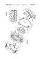
- FIG. 3is an exploded perspective view of one ear cup and yoke which forms part of the headphone of FIG. 1,
- FIG. 4is an exploded top view of the ear cup and yoke of FIG. 3,
- FIG. 5is a front elevation view of a ear plate which forms part of the headphone of FIG. 1, and
- FIG. 6is a cross section through the headphone of FIG. 1.
- the headphone of the present inventionincludes a headband 1 which supports a pair of ear cup assemblies 2 and 3 over the ears of a user.
- Each cup assembly 2 and 3is attached to the headband 1 by a metal yoke 4 and 5 respectively.
- Each yoke 4 and 5includes a bracket portion 6 which is fastened to one end of the headband 1 by a rivet that enables the yokes 4 and 5 to swivel.
- the ear cup assemblies 2 and 3are mounted to the headband 1 for pivotal motion about verticle axes.
- the yokes 4 and 5 as well as the ear cup assemblies 2 and 3are identical, and although the drawings and the following description refer to the yoke 5 and the ear cup assembly 3, the same applies to the ear cup assembly 2 and yoke 4.
- the yoke 5has a pair of legs 8a and 8b which extend downward and outward from the bracket 6 along a circular path. They connect to one another to form a rigid ring 9 that provides a firm supporting structure for the ear cup assembly 3.
- the yoke 5is stamped from metal and semicircular-shaped bights 10a and 10b are formed in the respective legs 8a and 8b.
- the bights 10a and 10bare located on opposite sides of the ring 9 along a substantially horizontal axis indicated by the dashed line 11 in FIG. 2.
- the ear cup assembly 3is attached to the yoke 5 at the bights 10a and 10b for pivotal motion about the horizontal axis 11.
- the ear cup assembly 3includes four primary elements: an ear cushion 13; a ear plate 14; an acoustic transducer 15; and a back plate 16.
- the ear plate 14 and the back plate 16are molded from ABS plastic and the acoustic transducer 15 is a self contained unit which is separately assembled.
- the cushion 13is molded from an open cell polyurethane foam as described in co-pending U.S. patent application Ser. No. 91,339 which was filed on Nov. 5, 1979, and which is entitled "Method for Molding Ear Cushions".
- the ear plate 14includes numerous elements which are integrally molded and which cooperate to fasten the four basic ear cup assembly elements together and to retain the resulting structure to the yoke 5. These include a circular plate portion 17 that has a centrally located pattern of openings 18 through which sound generated by the acoustic transducer 15 passes. The acoustic openings 18 are formed during the molding process and any number of patterns may be employed to achieve the desired acoustic effects.
- an annular shaped guideway 19is formed on the back surface of the plate 17.
- the guideway 19is spaced radially outward from and is concentric with the acoustic openings 18.
- the acoustic transducer 15has a flange 20 integrally formed around its circular periphery, and this flange 20 is received in the guideway 19 to align the acoustic transducer 15 over the acoustic openings 18.
- a set of four pawls 21are molded on the back surface of the ear plate 14 and these are located around the perimeter of the guideway 19.
- the pawls 21are deflected outward as the acoustic transducer 15 is inserted into the guideway 19, and when it is in place, the pawls snap over the flange 20 to firmly retain and fasten the acoustic transducer 15 to the ear plate 14.
- each opening 22Located radially outward from the four pawls 21 are four shaped openings 22 which serve as part of fastening means for retaining the ear cushion 13 and the back plate 16 to the ear plate 14.
- a relatively large rectangular portion 23 of each opening 22receives a latch 24 on the ear cushion 13 and a smaller portion 25 of each opening 22 receives a pawl 26 on the back plate 16.
- the foam portion of the ear cushion 13is bonded to the front surface of the support disc 27 and when it is rotated clockwise about an earphone sound emitting axis 28, the latches 24 hook the ear plate 14, slide across its rear surface, and snap into recesses 29 which are formed alongside each opening 22. Counterclockwise rotation of the ear cushion 13 unsnaps the latches 24 and enables the ear cushion to be withdrawn for cleaning or replacement.
- the ear plate 14also includes an integrally molded flange 30 which extends completely around the circular plate portion 17.
- the flange 30extends rearward from the plate portion 17 to present a rearward directed bearing surface 31.
- the bearing surface 31extends completely around the periphery of the ear plate 14 and it is contoured at the left and right sides of the ear plate 14 to form a pair of rearward extending projections 32. When assembled, as shown best in FIG. 2, these projections are received in the bights 10a and 10b formed in the yoke 5.
- the back plate 16is molded from ABS plastic and it has a substantially circular periphery which is defined by a forward extending side wall 34. As shown best in FIGS. 3, 4 and 5, the four pawls 26 are molded onto the leading edge of the side wall 34 and are arranged to pass through the openings 22 in the ear plate 14 when the back plate 16 is assembled. The pawls 26 pass through the smaller portions 25 of the openings 22 and they spring radially outward and over locking surfaces 35 formed on the front surface of the ear plate 14. A snap action fastening of the back plate 16 to the ear plate 14 is thus achieved.
- the back plate 16when assembled the back plate 16 nests within the raised flange 30 on the ear plate 14 to enclose the back of the acoustic transducer 15.
- the back plate 16also includes an integrally molded flange 36 which is formed by two radially extending portions 36a and 36b.
- the flange 36presents a forward directed bearing surface 37 which is divided into two portions 37a and 37b located on opposite sides of the back plate 14. These bearing surfaces 37a and 37b are countoured to form notches that receive the bights 10 in the yoke 5.
- the bearing surface 31 formed on the ear plate 14 and the bearing surface 37 formed on the back plate 16are spaced apart to form a channel in which the yoke 5 is entrapped.
- This channelis constricted over the contoured regions to snuggly bear against the bights 10 on the yoke 5.
- the yoke 5is free to pivot about the projections 32 and to thus enable the ear cup assembly 3 to adjust to the user's head by pivoting about the horizontal axis 11.
- the bearing surfaces 31 and 37are sloped in the region surrounding the constrictions to gradually widen the channel. This enables the ear cup assembly 3 to pivot over a range which is limited by the engagement of the yoke with the bearing surfaces 31 and 37. This motion limiting engagement is distributed over a large portion of the bearing surface 31. Localized stress in the materials is minimized and this enables the use of lighter weight construction which is consistant with the overall design objective of minimizing the weight of the headphone.
- the preferred embodiment of the inventionprovides a headphone construction which is light weight, durable and particularly easy to assemble. It should be apparent, however, that a number of variations can be made from this preferred construction without departing from the invention. For example, numerous variations are possible in the particular construction of the snap action fastening means used to hold the ear cup assembly elements together. Also, variations are possible in the shape of the ear cup assembly elements and in the shape of the yoke. Reference is therefore made to the following claims for a definition of the invention.
Landscapes
- Engineering & Computer Science (AREA)
- Manufacturing & Machinery (AREA)
- Physics & Mathematics (AREA)
- Acoustics & Sound (AREA)
- Signal Processing (AREA)
- Headphones And Earphones (AREA)
Abstract
Description
The field of the invention is headphones, and particularly, high quality headphones which are mass produced for the high fidelity market.
High quality headphones which are intended to reproduce high fidelity sound are manufactured in many shapes and sizes. Most of them, however, include one or more acoustic transducers which are held over the user's ears by a supporting structure which also encloses the acoustic transducer and provides an aesthetically pleasing appearance. In many headphones this supporting structure takes the form of a pair of ear cup assemblies which are held in place over the user's ears by a headband.
Because headphones may be worn for extended periods of time, user comfort is a major consideration in their design. This requires not only that the weight of the headphone be kept to a minimum, but also, that the ear cup assemblies be aligned correctly over the user's ears. The latter requirement is accomplished best by enabling each ear cup assembly to pivot about both a vertical axis and a horizontal axis. Numerous supporting structures which provide pivotal connection of the ear cup assemblies to the headband are known, and in most cases such structures include numerous parts which must be assembled with fasteners during manufacture.
The present invention relates to a headphone structure for supporting an acoustic transducer over the user's ear, which structure includes a minimal number of parts which are easily assembled during manufacture. More specifically, the headphone structure includes an earplate having first integrally formed snap action fastener means and second integrally formed snap action fastening means, an acoustic transducer mounted to the ear plate and fastened in position on its back surface by said first snap action fastening means, a back plate mounted to the ear plate and fastened in position over the acoustic transducer by said second snap action fastening means, and a yoke for attaching the headphone structure to a headband, the yoke being entrapped in a channel formed between the ear plate and the back plate.
A general object of the invention is to provide an easily assembled headphone structure. Each ear cup assembly includes four basic elements which are fastened together with integrally formed fastening devices. Parts are thus minimal in number and assembly requires only the application of force to operate the snap action fastening mechanisms. No fastener is required for the yoke which is held in place by entrapping it in a channel formed between the assembled ear plate and back plate.
A more specific object of the invention is to provide a reliable means for pivotally connecting an ear cup assembly to the yoke. Bearing surfaces are formed on the ear plate and the back plate and these form the channel in which the yoke is entrapped. These surfaces are contoured to form U-shaped constrictions on opposite sides of the ear cup assembly and the legs on the yoke are formed with bights that fit within these constrictions. The bearing surfaces adjacent to the constrictions are sloped to widen away from the constrictions and the resulting assembly enables the ear cup assembly to pivot about a horizontal axis which passes through the constricted regions. Pivotal motion is limited in both directions by the engagement of the yoke with a bearing surface.
Another specific object of the invention is to provide an easily assembled and removable ear cushion for a headphone. A third snap action fastener means is integrally formed on the front surface of the ear plate and an ear cushion having a molded annular shaped support disc is fastened to the front of the ear plate by the third snap action fastener means.
The foregoing and other objects and advantages of the invention will appear from the following description. In the description, reference is made to the accompanying drawings which form a part hereof, and in which there is shown by way of illustration a preferred embodiment of the invention. Such embodiment does not necessarily represent the full scope of the invention, however, and reference is made therefore to the claims herein for interpreting the scope of the invention.
FIG. 1 is a side elevation view of a headphone which incorporates the present invention,
FIG. 2 is a back elevation view of a portion of the headphone of FIG. 1,
FIG. 3 is an exploded perspective view of one ear cup and yoke which forms part of the headphone of FIG. 1,
FIG. 4 is an exploded top view of the ear cup and yoke of FIG. 3,
FIG. 5 is a front elevation view of a ear plate which forms part of the headphone of FIG. 1, and
FIG. 6 is a cross section through the headphone of FIG. 1.
Referring particularly to FIG. 1, the headphone of the present invention includes a headband 1 which supports a pair ofear cup assemblies cup assembly metal yoke yoke bracket portion 6 which is fastened to one end of the headband 1 by a rivet that enables theyokes yokes ear cup assemblies yoke 5 and theear cup assembly 3, the same applies to theear cup assembly 2 andyoke 4.
Referring particularly to FIGS. 2-4, theyoke 5 has a pair oflegs bracket 6 along a circular path. They connect to one another to form arigid ring 9 that provides a firm supporting structure for theear cup assembly 3. Theyoke 5 is stamped from metal and semicircular-shaped bights 10a and 10b are formed in therespective legs bights 10a and 10b are located on opposite sides of thering 9 along a substantially horizontal axis indicated by the dashed line 11 in FIG. 2. As will now be described in more detail, theear cup assembly 3 is attached to theyoke 5 at thebights 10a and 10b for pivotal motion about the horizontal axis 11.
As shown best in FIGS. 3 and 4, theear cup assembly 3 includes four primary elements: anear cushion 13; aear plate 14; anacoustic transducer 15; and aback plate 16. Theear plate 14 and theback plate 16 are molded from ABS plastic and theacoustic transducer 15 is a self contained unit which is separately assembled. Thecushion 13 is molded from an open cell polyurethane foam as described in co-pending U.S. patent application Ser. No. 91,339 which was filed on Nov. 5, 1979, and which is entitled "Method for Molding Ear Cushions".
Referring particularly to FIGS. 3-5, theear plate 14 includes numerous elements which are integrally molded and which cooperate to fasten the four basic ear cup assembly elements together and to retain the resulting structure to theyoke 5. These include acircular plate portion 17 that has a centrally located pattern ofopenings 18 through which sound generated by theacoustic transducer 15 passes. Theacoustic openings 18 are formed during the molding process and any number of patterns may be employed to achieve the desired acoustic effects.
As shown in FIG. 3, an annularshaped guideway 19 is formed on the back surface of theplate 17. Theguideway 19 is spaced radially outward from and is concentric with theacoustic openings 18. Theacoustic transducer 15 has aflange 20 integrally formed around its circular periphery, and thisflange 20 is received in theguideway 19 to align theacoustic transducer 15 over theacoustic openings 18. A set of fourpawls 21 are molded on the back surface of theear plate 14 and these are located around the perimeter of theguideway 19. Thepawls 21 are deflected outward as theacoustic transducer 15 is inserted into theguideway 19, and when it is in place, the pawls snap over theflange 20 to firmly retain and fasten theacoustic transducer 15 to theear plate 14.
Located radially outward from the fourpawls 21 are fourshaped openings 22 which serve as part of fastening means for retaining theear cushion 13 and theback plate 16 to theear plate 14. A relatively largerectangular portion 23 of eachopening 22 receives alatch 24 on theear cushion 13 and asmaller portion 25 of each opening 22 receives apawl 26 on theback plate 16. As shown best in FIGS. 3 and 4, there are fourlatches 24 formed on the back side of theear cushion 13. These latches are molded on a flat annularshaped support disc 27 and they extend rearward to form flexible arms that extend completely through theopenings 22 in theear plate 14. The foam portion of theear cushion 13 is bonded to the front surface of thesupport disc 27 and when it is rotated clockwise about an earphonesound emitting axis 28, thelatches 24 hook theear plate 14, slide across its rear surface, and snap into recesses 29 which are formed alongside eachopening 22. Counterclockwise rotation of theear cushion 13 unsnaps thelatches 24 and enables the ear cushion to be withdrawn for cleaning or replacement.
As shown best in FIG. 4, theear plate 14 also includes an integrally moldedflange 30 which extends completely around thecircular plate portion 17. Theflange 30 extends rearward from theplate portion 17 to present a rearward directedbearing surface 31. Thebearing surface 31 extends completely around the periphery of theear plate 14 and it is contoured at the left and right sides of theear plate 14 to form a pair of rearward extendingprojections 32. When assembled, as shown best in FIG. 2, these projections are received in thebights 10a and 10b formed in theyoke 5.
Theback plate 16 is molded from ABS plastic and it has a substantially circular periphery which is defined by a forward extendingside wall 34. As shown best in FIGS. 3, 4 and 5, the fourpawls 26 are molded onto the leading edge of theside wall 34 and are arranged to pass through theopenings 22 in theear plate 14 when theback plate 16 is assembled. Thepawls 26 pass through thesmaller portions 25 of theopenings 22 and they spring radially outward and over locking surfaces 35 formed on the front surface of theear plate 14. A snap action fastening of theback plate 16 to theear plate 14 is thus achieved.
As shown best in FIGS. 1-4, when assembled theback plate 16 nests within the raisedflange 30 on theear plate 14 to enclose the back of theacoustic transducer 15. Theback plate 16 also includes an integrally molded flange 36 which is formed by two radially extendingportions 36a and 36b. The flange 36 presents a forward directed bearing surface 37 which is divided into twoportions back plate 14. These bearing surfaces 37a and 37b are countoured to form notches that receive the bights 10 in theyoke 5.
As shown best in FIG. 1, the bearingsurface 31 formed on theear plate 14 and the bearing surface 37 formed on theback plate 16 are spaced apart to form a channel in which theyoke 5 is entrapped. This channel is constricted over the contoured regions to snuggly bear against the bights 10 on theyoke 5. Nevertheless, theyoke 5 is free to pivot about theprojections 32 and to thus enable theear cup assembly 3 to adjust to the user's head by pivoting about the horizontal axis 11. The bearing surfaces 31 and 37 are sloped in the region surrounding the constrictions to gradually widen the channel. This enables theear cup assembly 3 to pivot over a range which is limited by the engagement of the yoke with the bearing surfaces 31 and 37. This motion limiting engagement is distributed over a large portion of the bearingsurface 31. Localized stress in the materials is minimized and this enables the use of lighter weight construction which is consistant with the overall design objective of minimizing the weight of the headphone.
The preferred embodiment of the invention provides a headphone construction which is light weight, durable and particularly easy to assemble. It should be apparent, however, that a number of variations can be made from this preferred construction without departing from the invention. For example, numerous variations are possible in the particular construction of the snap action fastening means used to hold the ear cup assembly elements together. Also, variations are possible in the shape of the ear cup assembly elements and in the shape of the yoke. Reference is therefore made to the following claims for a definition of the invention.
Claims (18)
1. A headphone, the combination comprising:
an ear plate having acoustic openings distributed in a pattern around a sound emitting axis which passes through the ear plate;
an acoustic transducer disposed against the back surface of the ear plate and aligned over the acoustic openings;
first snap action fastening means for fastening the acoustic transducer to the ear plate, said first snap action fastening means having elements which are integrally formed on the ear plate and acoustic transducer;
a back plate disposed against the back surface of the ear plate to form an ear cup assembly which surrounds the acoustic transducer;
second snap action fastening means for fastening the back plate to the ear plate, said second snap action fastening means having elements which are integrally formed on the ear plate and back plate;
a headband for supporting the ear cup assembly over the ear of a listener; and
means for attaching the ear cup assembly to the headband.
2. The headphone as recited in claim 1 in which said means for attaching the ear cup assembly to the headband includes a yoke having a bracket which fastens to the headband and having a pair of legs which extend outward and downward from the bracket to make pivotal connection with the ear cup assembly.
3. The headphone as recited in claim 2 in which the pivotal connection of each leg to the ear cup assembly is accomplished by entrapping portions of each between the ear plate and back plate.
4. The headphone as recited in claim 1 in which means for attaching the ear cup assembly to the headband includes a yoke having a bracket which fastens to the headband and a ring which extends downward from the bracket to encircle a portion of the ear cup assembly and to make pivotal connection therewith.
5. The headphone as recited in claim 4 in which the ring includes a pair of bights and the pivotal connection with the ear cup assembly is accomplished by entrapping each bight in a constricted channel which is defined by a pair of opposing bearing surfaces formed respectively on the ear plate and the back plate.
6. The headphone as recited in claim 1 in which the acoustic transducer includes a flange around its periphery which is received in a guideway formed on the back surface of the ear plate and the first snap action fastening means includes pawls which are integrally formed on the back surface of the ear plate and located around the guideway.
7. The headphone as recited in claim 1 in which the second snap action fastening means includes a set of pawls integrally formed on the back plate and a set of corresponding openings in the ear plate through which the pawls extend.
8. The headphone as recited in claim 1 which includes an ear cushion having a support disc attached to its back surface and which includes third snap action fastening means for fastening the ear cushion to the front surface of the ear plate, said third snap action fastening means having elements which are integrally formed on the support disc and the front surface of the ear plate.
9. A headphone, the combination comprising;
an ear cup assembly having an ear plate in which acoustic openings are formed in a pattern about a sound emitting axis which extends through the ear plate and which includes a set of fastener openings disposed in a pattern radially outward from the acoustic openings;
an ear cushion having an annular shaped support disc attached to its back surface; and
a set of latches formed on the back surface of the support disc and aligned to extend through the fastener openings and engage the back surface of the ear plate to fasten the cushion to the ear cup assembly.
10. The headphone as recited in claim 9 in which recesses are formed on the back surface of the ear plate adjacent the fastener openings and the latches are moved along the back surface into the recesses by rotating the ear cushion about the sound emitting axis.
11. A headphone, the combination comprising:
an ear plate having acoustic openings disposed in a pattern around a sound emitting axis and having a flange formed on its periphery to provide a first bearing surface which is directed rearward;
an acoustic transducer mounted to the back of the ear plate to direct sound through the acoustic openings;
a back plate fastened to the ear plate to form an ear cup assembly which encloses the acoustic transducer, the back plate including a flange formed on its periphery which defines a second bearing surface which is directed forward toward the first bearing surface and is spaced therefrom to define a channel; and
a yoke for attaching the ear cup assembly to a headband, the yoke having a pair of legs which extend around the periphery of the back plate on opposite sides, each leg having a portion which extends into said channel and is entrapped therein to thereby fasten the yoke to the ear cup assembly.
12. The headphone as recited in claim 11, in which the first and second bearing surfaces are contoured at two regions on opposite sides of the ear cup to form constrictions at which points the legs of the yoke are entrapped.
13. The headphone as recited in claim 12 in which the legs of the yoke join to form a ring which encircles the ear assembly.
14. The headphone as recited in claim 11 in which the legs of the yoke join to form a ring which encircles the ear cup assembly.
15. The headphone as recited in claim 11 in which the first bearing surface is contoured to form rearward extending projections on the left and right sides of the ear cup assembly and the second bearing surface is contoured to form a pair of notches which receive the projections, and in which the legs of the yoke are joined to form a ring and bights are formed on opposite sides of the ring and are entrapped between the projections and their corresponding notches to provide a pivotal connection of the ear cup assembly with the yoke.
16. The headphone as recited in claim 15 in which the bearing surfaces are sloped in the regions surrounding the contoured areas to enable the ear cup assembly to pivot with respect to the yoke, and the ring engages said sloped bearing surfaces to limit the extent of pivotal motion.
17. A headphone, which comprises:
a headband for extending over the head of a user;
a yoke having a bracket which connects to one end of the headband and which includes a ring that extends downward from the bracket;
an ear cup assembly disposed within the ring; and
means for attaching the ear cup assembly to the ring to enable the ear cup assembly to pivot about a horizontal axis,
wherein the ear cup assembly includes a flange which extends completely around its periphery to present an annular shaped bearing surface, the bearing surface having a first sloped portion which engages the ring at points above the horizontal pivot axis when the ear cup assembly is pivoted in one direction, and a second sloped portion which engages the ring at points below the horizontal pivot axis when the ear cup assembly is pivoted in the other direction.
18. The headphone as recited in claim 17 in which said means for attaching includes elements formed on the ring which are received in channels formed on the left and right sides of the ear cup assembly by the assembly of its component parts.
Priority Applications (1)
| Application Number | Priority Date | Filing Date | Title |
|---|---|---|---|
| US06/109,504US4302635A (en) | 1980-01-04 | 1980-01-04 | Headphone construction |
Applications Claiming Priority (1)
| Application Number | Priority Date | Filing Date | Title |
|---|---|---|---|
| US06/109,504US4302635A (en) | 1980-01-04 | 1980-01-04 | Headphone construction |
Publications (1)
| Publication Number | Publication Date |
|---|---|
| US4302635Atrue US4302635A (en) | 1981-11-24 |
Family
ID=22328013
Family Applications (1)
| Application Number | Title | Priority Date | Filing Date |
|---|---|---|---|
| US06/109,504Expired - LifetimeUS4302635A (en) | 1980-01-04 | 1980-01-04 | Headphone construction |
Country Status (1)
| Country | Link |
|---|---|
| US (1) | US4302635A (en) |
Cited By (89)
| Publication number | Priority date | Publication date | Assignee | Title |
|---|---|---|---|---|
| USD265557S (en) | 1980-12-12 | 1982-07-27 | Koss Corporation | Stereo headphone |
| US4409442A (en)* | 1980-05-12 | 1983-10-11 | Hosiden Electronics Co., Ltd. | Headphone |
| US4420657A (en)* | 1981-10-29 | 1983-12-13 | Acs Communications, Inc. | Adjustable headset |
| US4588868A (en)* | 1984-07-12 | 1986-05-13 | Avicom International, Inc. | Headset |
| US4993074A (en)* | 1988-04-13 | 1991-02-12 | Carroll Robert J | Earphone spacer |
| US5056161A (en)* | 1989-09-26 | 1991-10-15 | Bose Corporation | Headset having reduced width nested bands which are grasped by earcup supporting block |
| US5257318A (en)* | 1989-01-11 | 1993-10-26 | Carroll Robert J | Earphone spacer with electronically variable sound level |
| US5357585A (en)* | 1993-07-09 | 1994-10-18 | Khyber Technologies Corporation | Headphone assembly |
| US5590213A (en)* | 1995-02-15 | 1996-12-31 | David Clark Company Inc. | Headset with adjustable headpad |
| USD391575S (en) | 1995-04-21 | 1998-03-03 | David Clark Company Inc. | Headset earcup |
| USD398309S (en) | 1996-04-18 | 1998-09-15 | David Clark Company Inc. | Headset |
| US5911314A (en)* | 1998-03-31 | 1999-06-15 | David Clark Company Inc. | Headset ear seal |
| US6163615A (en)* | 1997-08-06 | 2000-12-19 | University Research & Engineers & Associates, Inc. | Circumaural ear cup audio seal for use in connection with a headset, ear defender, helmet and the like |
| US20010040970A1 (en)* | 1998-08-03 | 2001-11-15 | Dage David Alan | Monopole low frequency test woofer |
| WO2002041608A1 (en)* | 2000-11-15 | 2002-05-23 | Gn Netcom A/S | Headset |
| US6466681B1 (en)* | 1999-09-21 | 2002-10-15 | Comprehensive Technical Solutions, Inc. | Weather resistant sound attenuating modular communications headset |
| US6856690B1 (en) | 2002-01-09 | 2005-02-15 | Plantronis, Inc. | Comfortable earphone cushions |
| US20050111687A1 (en)* | 2003-10-27 | 2005-05-26 | Wayne Lederer | Noise attenuating headset |
| US20050238181A1 (en)* | 2003-11-27 | 2005-10-27 | Sigvard Nilsson | Hearing protector |
| US20050286717A1 (en)* | 2004-06-23 | 2005-12-29 | Vocollect, Inc. | Method and system for an interchangeable headset module resistant to moisture infiltration |
| US20070053539A1 (en)* | 2005-09-05 | 2007-03-08 | Sony Corporation | Headphones and headphones placement device |
| US20070080930A1 (en)* | 2005-10-11 | 2007-04-12 | Logan James R | Terminal device for voice-directed work and information exchange |
| US20070183616A1 (en)* | 2006-02-06 | 2007-08-09 | James Wahl | Headset terminal with rear stability strap |
| USD549688S1 (en)* | 2006-01-10 | 2007-08-28 | Sony Corporation | Headphone |
| USD552595S1 (en) | 2005-11-16 | 2007-10-09 | Vocollect, Inc. | Control panel for a headset |
| US20070274529A1 (en)* | 2003-11-27 | 2007-11-29 | Henrik Nordin | Hearing Protector |
| US20080069391A1 (en)* | 2006-09-14 | 2008-03-20 | Phitek Systems Limited | Battery door |
| USD567219S1 (en) | 2005-11-15 | 2008-04-22 | Vocollect, Inc. | Headset |
| US20080187150A1 (en)* | 2005-04-29 | 2008-08-07 | Peltor Ab | Ear Cup With Micrphone Device |
| US20080192973A1 (en)* | 2005-04-29 | 2008-08-14 | Peltor Ab | Ear Cup |
| US20080226111A1 (en)* | 2007-03-12 | 2008-09-18 | Ching-Chi Wang | Headphone with components secured together by snapping |
| US20080311986A1 (en)* | 2007-03-12 | 2008-12-18 | Astro Gaming, Llc | Daisy-chained game audio exchange |
| US20090238397A1 (en)* | 2007-12-17 | 2009-09-24 | Astro Gaming, Llc | Headset with noise plates |
| US20090252352A1 (en)* | 2006-06-20 | 2009-10-08 | Peltor Ab | Ear cup |
| US20090262952A1 (en)* | 2008-04-22 | 2009-10-22 | Sennheiser Electronic Gmbh & Co. Kg | Earphone and headset |
| USD603370S1 (en)* | 2006-10-10 | 2009-11-03 | Sony Corporation | Headphone |
| US20090285433A1 (en)* | 2008-05-19 | 2009-11-19 | Chien-Cheng Yang | Headphone |
| USD605629S1 (en) | 2008-09-29 | 2009-12-08 | Vocollect, Inc. | Headset |
| USD626949S1 (en) | 2008-02-20 | 2010-11-09 | Vocollect Healthcare Systems, Inc. | Body-worn mobile device |
| US20110019834A1 (en)* | 2008-03-26 | 2011-01-27 | Henrik Fransson | Hearing protector |
| US7885419B2 (en) | 2006-02-06 | 2011-02-08 | Vocollect, Inc. | Headset terminal with speech functionality |
| US20110064239A1 (en)* | 2008-05-12 | 2011-03-17 | 3M Svenska Ab | Hearing protector |
| US20110107415A1 (en)* | 2009-11-05 | 2011-05-05 | Yangmin Shen | Portable computing device and headset interface |
| US20110130203A1 (en)* | 2009-12-02 | 2011-06-02 | Astro Gaming, Inc. | Wireless Game/Audio System and Method |
| ITRE20090120A1 (en)* | 2009-12-23 | 2011-06-24 | Cte Internat S R L | EARMUFFS |
| USD643013S1 (en) | 2010-08-20 | 2011-08-09 | Vocollect Healthcare Systems, Inc. | Body-worn mobile device |
| USD643400S1 (en) | 2010-08-19 | 2011-08-16 | Vocollect Healthcare Systems, Inc. | Body-worn mobile device |
| US20110225705A1 (en)* | 2010-03-16 | 2011-09-22 | 3M Innovative Properties Company | Hearing protective device with moisture resistant earmuff sound absorbers |
| US8130970B2 (en) | 2005-04-29 | 2012-03-06 | 3M Innovative Properties Company | Ear cup |
| US8128422B2 (en) | 2002-06-27 | 2012-03-06 | Vocollect, Inc. | Voice-directed portable terminals for wireless communication systems |
| US8160287B2 (en) | 2009-05-22 | 2012-04-17 | Vocollect, Inc. | Headset with adjustable headband |
| US8386261B2 (en) | 2008-11-14 | 2013-02-26 | Vocollect Healthcare Systems, Inc. | Training/coaching system for a voice-enabled work environment |
| US8417185B2 (en) | 2005-12-16 | 2013-04-09 | Vocollect, Inc. | Wireless headset and method for robust voice data communication |
| JP2013078013A (en)* | 2011-09-30 | 2013-04-25 | Jvc Kenwood Corp | Headphone |
| JP2013078014A (en)* | 2011-09-30 | 2013-04-25 | Jvc Kenwood Corp | Headphone |
| USD685759S1 (en)* | 2011-12-19 | 2013-07-09 | Skullcandy, Inc. | Headphone |
| US8602892B1 (en) | 2006-08-23 | 2013-12-10 | Ag Acquisition Corporation | Game system mixing player voice signals with game sound signal |
| US8659397B2 (en) | 2010-07-22 | 2014-02-25 | Vocollect, Inc. | Method and system for correctly identifying specific RFID tags |
| USD701196S1 (en) | 2012-12-26 | 2014-03-18 | Skullcandy, Inc. | Headphone |
| USD701197S1 (en) | 2012-12-26 | 2014-03-18 | Skullcandy, Inc. | Headphone |
| US20140177884A1 (en)* | 2012-11-29 | 2014-06-26 | Polk Audio, Inc. | Personalized modular headphone system and method |
| USD733682S1 (en) | 2013-09-25 | 2015-07-07 | Skullcandy, Inc. | Portable speaker |
| USD736176S1 (en)* | 2014-07-08 | 2015-08-11 | Akg Acoustics Gmbh | Headphones |
| USD754632S1 (en)* | 2014-10-28 | 2016-04-26 | Pioneer Dj Corporation | Headphone |
| US9332337B2 (en)* | 2009-03-02 | 2016-05-03 | Gn Netcom A/S | Headset with magnetically attached ear pad |
| USD760689S1 (en) | 2015-10-08 | 2016-07-05 | Raymond Gecawicz | Headset |
| USD760690S1 (en) | 2015-10-09 | 2016-07-05 | Raymond Gecawicz | Headset |
| US9675871B1 (en) | 2013-03-15 | 2017-06-13 | Ag Acquisition Corporation | PC transceiver and method of using the same |
| US20170245787A1 (en)* | 2014-09-19 | 2017-08-31 | 3M Innovative Properties Company | Acoustically probed over-the-ear hearing assessment devices and methods |
| US20170264984A1 (en)* | 2016-03-10 | 2017-09-14 | Princeton Audio, LLC | Headphone System And Components Thereof |
| US20170318371A1 (en)* | 2016-04-27 | 2017-11-02 | Carl McAllister | Headphone Protector |
| US9813799B2 (en) | 2015-01-05 | 2017-11-07 | Raymond Gecawicz | Modular headset with pivotable boom and speaker module |
| US9973854B1 (en)* | 2016-11-16 | 2018-05-15 | Trent Zimmer | Electronic headset |
| WO2018199873A1 (en) | 2017-04-25 | 2018-11-01 | Shymanovych Pavlo Olegovych | Headphones or a headset with a planar magnetic system |
| US10129631B2 (en) | 2015-08-26 | 2018-11-13 | Logitech Europe, S.A. | System and method for open to closed-back headset audio compensation |
| US10375464B2 (en)* | 2016-05-14 | 2019-08-06 | Qingdao GoerTeck Technology Co., Ltd. | Adjustable head-mounted structure |
| EP3585064A1 (en) | 2018-06-20 | 2019-12-25 | B&B Electronics AG | Earphone |
| US10556179B2 (en) | 2017-06-09 | 2020-02-11 | Performance Designed Products Llc | Video game audio controller |
| USD890129S1 (en)* | 2018-08-01 | 2020-07-14 | Suyun Liu | Headphone |
| USD912643S1 (en)* | 2018-08-01 | 2021-03-09 | Sintai Optical (Shenzhen) Co., Ltd. | Headphone |
| USD916681S1 (en)* | 2020-08-06 | 2021-04-20 | Liu He | Headset |
| US10999672B2 (en)* | 2019-10-08 | 2021-05-04 | Kingston Technology Corporation | Acoustic chambers to improve sound reproduction between left and right earcups |
| USD953288S1 (en)* | 2020-06-22 | 2022-05-31 | Apple Inc. | Component for a headphone |
| US20230139105A1 (en)* | 2021-11-02 | 2023-05-04 | Lightspeed Aviation, Inc. | Circumaural ear cushion/seal |
| US20230284726A1 (en)* | 2020-09-30 | 2023-09-14 | ResMed Asia Pte. Ltd. | Headgear |
| USD1010612S1 (en) | 2021-12-20 | 2024-01-09 | Raymond Gecawicz | Headset |
| US20240048887A1 (en)* | 2022-08-05 | 2024-02-08 | Bose Corporation | Headphones |
| US20240080598A1 (en)* | 2022-09-07 | 2024-03-07 | Sony Interactive Entertainment LLC | Headset with reciprocating microphone support |
| USD1081617S1 (en)* | 2023-03-27 | 2025-07-01 | Alphatheta Corporation | Headphone |
Citations (9)
| Publication number | Priority date | Publication date | Assignee | Title |
|---|---|---|---|---|
| US2989598A (en)* | 1960-02-24 | 1961-06-20 | Martin L Touger | Hard shell liquid seal earmuff with isolated inner close coupling ear shell |
| US3447160A (en)* | 1965-11-29 | 1969-06-03 | Telex Corp The | Adjustable headset |
| US3579640A (en)* | 1970-02-11 | 1971-05-25 | American Optical Corp | Hearing protector headsets |
| US3787899A (en)* | 1972-07-11 | 1974-01-29 | Imp Optical Co Ltd | Ear muff assembly |
| US3875592A (en)* | 1973-01-10 | 1975-04-08 | Gentex Corp | Sound attenuating earcup |
| US4027113A (en)* | 1974-09-12 | 1977-05-31 | Nippon Gakki Seizo Kabushiki Kaisha | Headphone |
| US4041256A (en)* | 1975-05-06 | 1977-08-09 | Victor Company Of Japan, Limited | Open-back type headphone with a detachable attachment |
| US4058688A (en)* | 1975-05-27 | 1977-11-15 | Matsushita Electric Industrial Co., Ltd. | Headphone |
| US4156118A (en)* | 1978-04-10 | 1979-05-22 | Hargrave Frances E | Audiometric headset |
- 1980
- 1980-01-04USUS06/109,504patent/US4302635A/ennot_activeExpired - Lifetime
Patent Citations (9)
| Publication number | Priority date | Publication date | Assignee | Title |
|---|---|---|---|---|
| US2989598A (en)* | 1960-02-24 | 1961-06-20 | Martin L Touger | Hard shell liquid seal earmuff with isolated inner close coupling ear shell |
| US3447160A (en)* | 1965-11-29 | 1969-06-03 | Telex Corp The | Adjustable headset |
| US3579640A (en)* | 1970-02-11 | 1971-05-25 | American Optical Corp | Hearing protector headsets |
| US3787899A (en)* | 1972-07-11 | 1974-01-29 | Imp Optical Co Ltd | Ear muff assembly |
| US3875592A (en)* | 1973-01-10 | 1975-04-08 | Gentex Corp | Sound attenuating earcup |
| US4027113A (en)* | 1974-09-12 | 1977-05-31 | Nippon Gakki Seizo Kabushiki Kaisha | Headphone |
| US4041256A (en)* | 1975-05-06 | 1977-08-09 | Victor Company Of Japan, Limited | Open-back type headphone with a detachable attachment |
| US4058688A (en)* | 1975-05-27 | 1977-11-15 | Matsushita Electric Industrial Co., Ltd. | Headphone |
| US4156118A (en)* | 1978-04-10 | 1979-05-22 | Hargrave Frances E | Audiometric headset |
Cited By (139)
| Publication number | Priority date | Publication date | Assignee | Title |
|---|---|---|---|---|
| US4409442A (en)* | 1980-05-12 | 1983-10-11 | Hosiden Electronics Co., Ltd. | Headphone |
| USD265557S (en) | 1980-12-12 | 1982-07-27 | Koss Corporation | Stereo headphone |
| US4420657A (en)* | 1981-10-29 | 1983-12-13 | Acs Communications, Inc. | Adjustable headset |
| US4588868A (en)* | 1984-07-12 | 1986-05-13 | Avicom International, Inc. | Headset |
| US4993074A (en)* | 1988-04-13 | 1991-02-12 | Carroll Robert J | Earphone spacer |
| US5257318A (en)* | 1989-01-11 | 1993-10-26 | Carroll Robert J | Earphone spacer with electronically variable sound level |
| US5056161A (en)* | 1989-09-26 | 1991-10-15 | Bose Corporation | Headset having reduced width nested bands which are grasped by earcup supporting block |
| US5357585A (en)* | 1993-07-09 | 1994-10-18 | Khyber Technologies Corporation | Headphone assembly |
| US5519783A (en)* | 1993-07-09 | 1996-05-21 | Khyber Technologies Corporation | Headphone assembly |
| US5590213A (en)* | 1995-02-15 | 1996-12-31 | David Clark Company Inc. | Headset with adjustable headpad |
| USD391575S (en) | 1995-04-21 | 1998-03-03 | David Clark Company Inc. | Headset earcup |
| USD398309S (en) | 1996-04-18 | 1998-09-15 | David Clark Company Inc. | Headset |
| US6163615A (en)* | 1997-08-06 | 2000-12-19 | University Research & Engineers & Associates, Inc. | Circumaural ear cup audio seal for use in connection with a headset, ear defender, helmet and the like |
| US5911314A (en)* | 1998-03-31 | 1999-06-15 | David Clark Company Inc. | Headset ear seal |
| US20010040970A1 (en)* | 1998-08-03 | 2001-11-15 | Dage David Alan | Monopole low frequency test woofer |
| US6937740B2 (en)* | 1998-08-03 | 2005-08-30 | Visteon Global Technologies, Inc. | Monopole low frequency test woofer |
| US6466681B1 (en)* | 1999-09-21 | 2002-10-15 | Comprehensive Technical Solutions, Inc. | Weather resistant sound attenuating modular communications headset |
| WO2002041608A1 (en)* | 2000-11-15 | 2002-05-23 | Gn Netcom A/S | Headset |
| US6760458B1 (en) | 2000-11-15 | 2004-07-06 | Gn Netcom, Inc. | Headset and method of manufacturing headsets that utilize a single transceiver form-factor design with a number of different housing styles |
| US20040190744A1 (en)* | 2000-11-15 | 2004-09-30 | Tom Bogeskov-Jensen | Communications headset |
| US6856690B1 (en) | 2002-01-09 | 2005-02-15 | Plantronis, Inc. | Comfortable earphone cushions |
| US8128422B2 (en) | 2002-06-27 | 2012-03-06 | Vocollect, Inc. | Voice-directed portable terminals for wireless communication systems |
| US20050111687A1 (en)* | 2003-10-27 | 2005-05-26 | Wayne Lederer | Noise attenuating headset |
| US7292704B2 (en)* | 2003-10-27 | 2007-11-06 | Wayne Lederer | Noise attenuating headset |
| US7609844B2 (en) | 2003-10-27 | 2009-10-27 | Wayne Lederer | Noise attenuating headset |
| USRE43595E1 (en) | 2003-10-27 | 2012-08-21 | Wayne Lederer | Noise attenuating headset |
| US20080013775A1 (en)* | 2003-10-27 | 2008-01-17 | Wayne Lederer | Noise Attenuating Headset |
| US20050238181A1 (en)* | 2003-11-27 | 2005-10-27 | Sigvard Nilsson | Hearing protector |
| US8243943B2 (en) | 2003-11-27 | 2012-08-14 | 3M Svenska Aktiebolag | Hearing protector with removable microphone, amplifier, and loudspeaker unit |
| US20070274529A1 (en)* | 2003-11-27 | 2007-11-29 | Henrik Nordin | Hearing Protector |
| US7391863B2 (en)* | 2004-06-23 | 2008-06-24 | Vocollect, Inc. | Method and system for an interchangeable headset module resistant to moisture infiltration |
| US20050286717A1 (en)* | 2004-06-23 | 2005-12-29 | Vocollect, Inc. | Method and system for an interchangeable headset module resistant to moisture infiltration |
| US8189801B2 (en)* | 2005-04-29 | 2012-05-29 | 3M Svenska Aktiebolag | Ear cup |
| US8224011B2 (en) | 2005-04-29 | 2012-07-17 | 3M Innovative Properties Company | Ear cup with microphone device |
| US20080187150A1 (en)* | 2005-04-29 | 2008-08-07 | Peltor Ab | Ear Cup With Micrphone Device |
| US20080192973A1 (en)* | 2005-04-29 | 2008-08-14 | Peltor Ab | Ear Cup |
| US8130970B2 (en) | 2005-04-29 | 2012-03-06 | 3M Innovative Properties Company | Ear cup |
| US20070053539A1 (en)* | 2005-09-05 | 2007-03-08 | Sony Corporation | Headphones and headphones placement device |
| US7853035B2 (en)* | 2005-09-05 | 2010-12-14 | Sony Corporation | Headphones and headphones placement device |
| US20070080930A1 (en)* | 2005-10-11 | 2007-04-12 | Logan James R | Terminal device for voice-directed work and information exchange |
| USD567219S1 (en) | 2005-11-15 | 2008-04-22 | Vocollect, Inc. | Headset |
| USD567799S1 (en) | 2005-11-15 | 2008-04-29 | Vocollect, Inc. | Headset |
| USD567806S1 (en) | 2005-11-15 | 2008-04-29 | Vocollect, Inc. | Headset |
| USD567218S1 (en) | 2005-11-16 | 2008-04-22 | Vocollect, Inc. | Control panel for a headset |
| USD552595S1 (en) | 2005-11-16 | 2007-10-09 | Vocollect, Inc. | Control panel for a headset |
| US8417185B2 (en) | 2005-12-16 | 2013-04-09 | Vocollect, Inc. | Wireless headset and method for robust voice data communication |
| USD549688S1 (en)* | 2006-01-10 | 2007-08-28 | Sony Corporation | Headphone |
| US7885419B2 (en) | 2006-02-06 | 2011-02-08 | Vocollect, Inc. | Headset terminal with speech functionality |
| US8842849B2 (en) | 2006-02-06 | 2014-09-23 | Vocollect, Inc. | Headset terminal with speech functionality |
| US20070223766A1 (en)* | 2006-02-06 | 2007-09-27 | Michael Davis | Headset terminal with rear stability strap |
| US20110116672A1 (en)* | 2006-02-06 | 2011-05-19 | James Wahl | Headset terminal with speech functionality |
| US7773767B2 (en) | 2006-02-06 | 2010-08-10 | Vocollect, Inc. | Headset terminal with rear stability strap |
| US20070183616A1 (en)* | 2006-02-06 | 2007-08-09 | James Wahl | Headset terminal with rear stability strap |
| US20090252352A1 (en)* | 2006-06-20 | 2009-10-08 | Peltor Ab | Ear cup |
| US8130985B2 (en)* | 2006-06-20 | 2012-03-06 | 3M Innovative Properties Company | Ear cup with bone conduction microphone |
| US8602892B1 (en) | 2006-08-23 | 2013-12-10 | Ag Acquisition Corporation | Game system mixing player voice signals with game sound signal |
| US20080069391A1 (en)* | 2006-09-14 | 2008-03-20 | Phitek Systems Limited | Battery door |
| USD603370S1 (en)* | 2006-10-10 | 2009-11-03 | Sony Corporation | Headphone |
| US20080311986A1 (en)* | 2007-03-12 | 2008-12-18 | Astro Gaming, Llc | Daisy-chained game audio exchange |
| US8571695B2 (en) | 2007-03-12 | 2013-10-29 | Ag Acquisition Corporation | Daisy-chained game audio exchange |
| US20080226111A1 (en)* | 2007-03-12 | 2008-09-18 | Ching-Chi Wang | Headphone with components secured together by snapping |
| US8335335B2 (en) | 2007-12-17 | 2012-12-18 | Astro Gaming, Inc. | Headset with noise plates |
| US20090238397A1 (en)* | 2007-12-17 | 2009-09-24 | Astro Gaming, Llc | Headset with noise plates |
| US8139807B2 (en)* | 2007-12-17 | 2012-03-20 | Astro Gaming, Inc. | Headset with noise plates |
| USD626949S1 (en) | 2008-02-20 | 2010-11-09 | Vocollect Healthcare Systems, Inc. | Body-worn mobile device |
| US20110019834A1 (en)* | 2008-03-26 | 2011-01-27 | Henrik Fransson | Hearing protector |
| US8995676B2 (en) | 2008-03-26 | 2015-03-31 | 3M Svenska Ab | Hearing protector |
| DE102008020264B4 (en) | 2008-04-22 | 2018-12-13 | Sennheiser Electronic Gmbh & Co. Kg | Handset and headset |
| US20090262952A1 (en)* | 2008-04-22 | 2009-10-22 | Sennheiser Electronic Gmbh & Co. Kg | Earphone and headset |
| US8369557B2 (en)* | 2008-04-22 | 2013-02-05 | Sennheiser Electronic Gmbh & Co. Kg | Earphone and headset |
| US20110064239A1 (en)* | 2008-05-12 | 2011-03-17 | 3M Svenska Ab | Hearing protector |
| US9131310B2 (en) | 2008-05-12 | 2015-09-08 | 3M Innovative Properties Company | Hearing protector |
| US20090285433A1 (en)* | 2008-05-19 | 2009-11-19 | Chien-Cheng Yang | Headphone |
| US8027501B2 (en)* | 2008-05-19 | 2011-09-27 | Merry Electronics Co., Ltd. | Headphone |
| USD616419S1 (en) | 2008-09-29 | 2010-05-25 | Vocollect, Inc. | Headset |
| USD605629S1 (en) | 2008-09-29 | 2009-12-08 | Vocollect, Inc. | Headset |
| USD613267S1 (en) | 2008-09-29 | 2010-04-06 | Vocollect, Inc. | Headset |
| US8386261B2 (en) | 2008-11-14 | 2013-02-26 | Vocollect Healthcare Systems, Inc. | Training/coaching system for a voice-enabled work environment |
| US9332337B2 (en)* | 2009-03-02 | 2016-05-03 | Gn Netcom A/S | Headset with magnetically attached ear pad |
| US8160287B2 (en) | 2009-05-22 | 2012-04-17 | Vocollect, Inc. | Headset with adjustable headband |
| US20110107415A1 (en)* | 2009-11-05 | 2011-05-05 | Yangmin Shen | Portable computing device and headset interface |
| US8438659B2 (en) | 2009-11-05 | 2013-05-07 | Vocollect, Inc. | Portable computing device and headset interface |
| US10124264B2 (en) | 2009-12-02 | 2018-11-13 | Logitech Europe, S.A. | Wireless game/audio system and method |
| US8491386B2 (en) | 2009-12-02 | 2013-07-23 | Astro Gaming, Inc. | Systems and methods for remotely mixing multiple audio signals |
| US20110130203A1 (en)* | 2009-12-02 | 2011-06-02 | Astro Gaming, Inc. | Wireless Game/Audio System and Method |
| ITRE20090120A1 (en)* | 2009-12-23 | 2011-06-24 | Cte Internat S R L | EARMUFFS |
| US20110225705A1 (en)* | 2010-03-16 | 2011-09-22 | 3M Innovative Properties Company | Hearing protective device with moisture resistant earmuff sound absorbers |
| US8659397B2 (en) | 2010-07-22 | 2014-02-25 | Vocollect, Inc. | Method and system for correctly identifying specific RFID tags |
| US10108824B2 (en) | 2010-07-22 | 2018-10-23 | Vocollect, Inc. | Method and system for correctly identifying specific RFID tags |
| US9449205B2 (en) | 2010-07-22 | 2016-09-20 | Vocollect, Inc. | Method and system for correctly identifying specific RFID tags |
| US8933791B2 (en) | 2010-07-22 | 2015-01-13 | Vocollect, Inc. | Method and system for correctly identifying specific RFID tags |
| USD643400S1 (en) | 2010-08-19 | 2011-08-16 | Vocollect Healthcare Systems, Inc. | Body-worn mobile device |
| USD643013S1 (en) | 2010-08-20 | 2011-08-09 | Vocollect Healthcare Systems, Inc. | Body-worn mobile device |
| JP2013078014A (en)* | 2011-09-30 | 2013-04-25 | Jvc Kenwood Corp | Headphone |
| JP2013078013A (en)* | 2011-09-30 | 2013-04-25 | Jvc Kenwood Corp | Headphone |
| USD701193S1 (en)* | 2011-12-19 | 2014-03-18 | Skullcandy, Inc. | Headphone |
| USD685759S1 (en)* | 2011-12-19 | 2013-07-09 | Skullcandy, Inc. | Headphone |
| US9226060B2 (en)* | 2012-11-29 | 2015-12-29 | Directed, Llc | Personalized modular headphone system and method |
| US20140177884A1 (en)* | 2012-11-29 | 2014-06-26 | Polk Audio, Inc. | Personalized modular headphone system and method |
| USD701197S1 (en) | 2012-12-26 | 2014-03-18 | Skullcandy, Inc. | Headphone |
| USD701196S1 (en) | 2012-12-26 | 2014-03-18 | Skullcandy, Inc. | Headphone |
| US9675871B1 (en) | 2013-03-15 | 2017-06-13 | Ag Acquisition Corporation | PC transceiver and method of using the same |
| USD733682S1 (en) | 2013-09-25 | 2015-07-07 | Skullcandy, Inc. | Portable speaker |
| USD736176S1 (en)* | 2014-07-08 | 2015-08-11 | Akg Acoustics Gmbh | Headphones |
| RU2679108C2 (en)* | 2014-09-19 | 2019-02-05 | 3М Инновейтив Пропертиз Компани | On-ear hearing protector containing acoustic port with possibility of estimating efficiency thereof and methods of efficiency estimation |
| US20170245787A1 (en)* | 2014-09-19 | 2017-08-31 | 3M Innovative Properties Company | Acoustically probed over-the-ear hearing assessment devices and methods |
| US11707210B2 (en) | 2014-09-19 | 2023-07-25 | 3M Innovative Properties Company | Acoustically probed over-the-ear hearing assessment devices and methods |
| US10617333B2 (en) | 2014-09-19 | 2020-04-14 | 3M Innovative Properties Company | Acoustically probed over-the-ear hearing assessment devices and methods |
| USD754632S1 (en)* | 2014-10-28 | 2016-04-26 | Pioneer Dj Corporation | Headphone |
| US9813799B2 (en) | 2015-01-05 | 2017-11-07 | Raymond Gecawicz | Modular headset with pivotable boom and speaker module |
| US10129631B2 (en) | 2015-08-26 | 2018-11-13 | Logitech Europe, S.A. | System and method for open to closed-back headset audio compensation |
| USD760689S1 (en) | 2015-10-08 | 2016-07-05 | Raymond Gecawicz | Headset |
| USD760690S1 (en) | 2015-10-09 | 2016-07-05 | Raymond Gecawicz | Headset |
| US20170264984A1 (en)* | 2016-03-10 | 2017-09-14 | Princeton Audio, LLC | Headphone System And Components Thereof |
| US20170318371A1 (en)* | 2016-04-27 | 2017-11-02 | Carl McAllister | Headphone Protector |
| US10375464B2 (en)* | 2016-05-14 | 2019-08-06 | Qingdao GoerTeck Technology Co., Ltd. | Adjustable head-mounted structure |
| US9973854B1 (en)* | 2016-11-16 | 2018-05-15 | Trent Zimmer | Electronic headset |
| US10743096B2 (en) | 2017-04-25 | 2020-08-11 | Pavlo Olegovych Shymanovych | Headphones or a headset with a planar magnetic system |
| WO2018199873A1 (en) | 2017-04-25 | 2018-11-01 | Shymanovych Pavlo Olegovych | Headphones or a headset with a planar magnetic system |
| US10556179B2 (en) | 2017-06-09 | 2020-02-11 | Performance Designed Products Llc | Video game audio controller |
| EP3585064A1 (en) | 2018-06-20 | 2019-12-25 | B&B Electronics AG | Earphone |
| USD890129S1 (en)* | 2018-08-01 | 2020-07-14 | Suyun Liu | Headphone |
| USD912643S1 (en)* | 2018-08-01 | 2021-03-09 | Sintai Optical (Shenzhen) Co., Ltd. | Headphone |
| US10999672B2 (en)* | 2019-10-08 | 2021-05-04 | Kingston Technology Corporation | Acoustic chambers to improve sound reproduction between left and right earcups |
| USD1018499S1 (en) | 2020-06-22 | 2024-03-19 | Apple Inc. | Component for a headphone |
| USD1057682S1 (en) | 2020-06-22 | 2025-01-14 | Apple Inc. | Component for a headphone |
| USD991217S1 (en) | 2020-06-22 | 2023-07-04 | Apple Inc. | Component for a headphone |
| USD953288S1 (en)* | 2020-06-22 | 2022-05-31 | Apple Inc. | Component for a headphone |
| USD968364S1 (en) | 2020-06-22 | 2022-11-01 | Apple Inc. | Component for a headphone |
| USD916681S1 (en)* | 2020-08-06 | 2021-04-20 | Liu He | Headset |
| US12156563B2 (en)* | 2020-09-30 | 2024-12-03 | ResMed Asia Pte. Ltd. | Headgear |
| US20230284726A1 (en)* | 2020-09-30 | 2023-09-14 | ResMed Asia Pte. Ltd. | Headgear |
| US20230139105A1 (en)* | 2021-11-02 | 2023-05-04 | Lightspeed Aviation, Inc. | Circumaural ear cushion/seal |
| USD1010612S1 (en) | 2021-12-20 | 2024-01-09 | Raymond Gecawicz | Headset |
| US20240048887A1 (en)* | 2022-08-05 | 2024-02-08 | Bose Corporation | Headphones |
| US12302050B2 (en)* | 2022-08-05 | 2025-05-13 | Bose Corporation | Headphones |
| US20240080598A1 (en)* | 2022-09-07 | 2024-03-07 | Sony Interactive Entertainment LLC | Headset with reciprocating microphone support |
| US12382206B2 (en)* | 2022-09-07 | 2025-08-05 | Sony Interactive Entertainment LLC | Headset with reciprocating microphone support |
| USD1081617S1 (en)* | 2023-03-27 | 2025-07-01 | Alphatheta Corporation | Headphone |
Similar Documents
| Publication | Publication Date | Title |
|---|---|---|
| US4302635A (en) | Headphone construction | |
| US3272926A (en) | Headphone assembly | |
| US9930433B2 (en) | External attachments for speakers in seats | |
| US10764671B2 (en) | Headband assembly | |
| US4032725A (en) | Speaker mounting | |
| US6550866B1 (en) | Chair backrest with ventilating function | |
| CN104890552B (en) | Trim and foam assembly for vehicle seat | |
| US4058688A (en) | Headphone | |
| JP2019513102A (en) | Speaker grille assembly for vehicle seat | |
| US5331119A (en) | Speaker support frame | |
| JP2021527350A (en) | Loudspeaker with 3D printed lattice grille | |
| JP7703524B2 (en) | Ear covers | |
| JP2023524991A (en) | Headset mechanism for comfortable coupling of the earcups to the head | |
| US11931665B2 (en) | Toy system and toy figure head and headwear | |
| US9022482B2 (en) | Stretching structure of a tension member for a chair | |
| US20210352988A1 (en) | Replaceable earmuffs | |
| CN221429067U (en) | Earmuff fixed knot constructs and headphone | |
| JPH0470468U (en) | ||
| USD1034162S1 (en) | Fastening holder for cables | |
| JP2020151052A (en) | Sheet with speaker | |
| TW202133911A (en) | Toy with interchangeable parts having selectively engageable fasteners | |
| JPS5850702Y2 (en) | headphone | |
| WO2025181606A1 (en) | Earcup and headgear | |
| WO2025181613A1 (en) | Earcup and headgear | |
| KR200391732Y1 (en) | Net fixing structure for the net backrest of chair |
Legal Events
| Date | Code | Title | Description |
|---|---|---|---|
| STCF | Information on status: patent grant | Free format text:PATENTED CASE |