US4300497A - Prevaporizing diesel precombustion chamber - Google Patents
Prevaporizing diesel precombustion chamberDownload PDFInfo
- Publication number
- US4300497A US4300497AUS06/164,395US16439580AUS4300497AUS 4300497 AUS4300497 AUS 4300497AUS 16439580 AUS16439580 AUS 16439580AUS 4300497 AUS4300497 AUS 4300497A
- Authority
- US
- United States
- Prior art keywords
- precombustion chamber
- diesel engine
- fuel
- chamber
- opening
- Prior art date
- Legal status (The legal status is an assumption and is not a legal conclusion. Google has not performed a legal analysis and makes no representation as to the accuracy of the status listed.)
- Expired - Lifetime
Links
- 239000000446fuelSubstances0.000claimsabstractdescription39
- 238000002156mixingMethods0.000claimsabstractdescription10
- 230000006835compressionEffects0.000claimsabstractdescription7
- 238000007906compressionMethods0.000claimsabstractdescription7
- 238000009834vaporizationMethods0.000claimsdescription6
- 230000008016vaporizationEffects0.000claimsdescription6
- 239000011810insulating materialSubstances0.000claimsdescription2
- 230000006641stabilisationEffects0.000claims3
- 238000011105stabilizationMethods0.000claims3
- 238000002955isolationMethods0.000abstractdescription7
- 238000002485combustion reactionMethods0.000description8
- 230000035939shockEffects0.000description6
- 230000001965increasing effectEffects0.000description4
- 230000015572biosynthetic processEffects0.000description2
- 230000002708enhancing effectEffects0.000description2
- 238000010438heat treatmentMethods0.000description2
- 238000003915air pollutionMethods0.000description1
- 238000010420art techniqueMethods0.000description1
- 239000000919ceramicSubstances0.000description1
- 239000003344environmental pollutantSubstances0.000description1
- 239000007789gasSubstances0.000description1
- 238000009413insulationMethods0.000description1
- 238000004519manufacturing processMethods0.000description1
- 239000000203mixtureSubstances0.000description1
- 238000012986modificationMethods0.000description1
- 230000004048modificationEffects0.000description1
- 239000003208petroleumSubstances0.000description1
- 231100000719pollutantToxicity0.000description1
- 238000007493shaping processMethods0.000description1
- 239000007921spraySubstances0.000description1
- 239000010409thin filmSubstances0.000description1
Images
Classifications
- F—MECHANICAL ENGINEERING; LIGHTING; HEATING; WEAPONS; BLASTING
- F02—COMBUSTION ENGINES; HOT-GAS OR COMBUSTION-PRODUCT ENGINE PLANTS
- F02B—INTERNAL-COMBUSTION PISTON ENGINES; COMBUSTION ENGINES IN GENERAL
- F02B19/00—Engines characterised by precombustion chambers
- F02B19/16—Chamber shapes or constructions not specific to sub-groups F02B19/02 - F02B19/10
- F02B19/165—The shape or construction of the pre-combustion chambers is specially adapted to be formed, at least in part, of ceramic material
- F—MECHANICAL ENGINEERING; LIGHTING; HEATING; WEAPONS; BLASTING
- F02—COMBUSTION ENGINES; HOT-GAS OR COMBUSTION-PRODUCT ENGINE PLANTS
- F02B—INTERNAL-COMBUSTION PISTON ENGINES; COMBUSTION ENGINES IN GENERAL
- F02B19/00—Engines characterised by precombustion chambers
- F02B19/02—Engines characterised by precombustion chambers the chamber being periodically isolated from its cylinder
- F—MECHANICAL ENGINEERING; LIGHTING; HEATING; WEAPONS; BLASTING
- F02—COMBUSTION ENGINES; HOT-GAS OR COMBUSTION-PRODUCT ENGINE PLANTS
- F02B—INTERNAL-COMBUSTION PISTON ENGINES; COMBUSTION ENGINES IN GENERAL
- F02B19/00—Engines characterised by precombustion chambers
- F02B2019/002—Engines characterised by precombustion chambers with electric heater fitted to at least part of prechamber-wall or transfer passage
- F—MECHANICAL ENGINEERING; LIGHTING; HEATING; WEAPONS; BLASTING
- F02—COMBUSTION ENGINES; HOT-GAS OR COMBUSTION-PRODUCT ENGINE PLANTS
- F02B—INTERNAL-COMBUSTION PISTON ENGINES; COMBUSTION ENGINES IN GENERAL
- F02B3/00—Engines characterised by air compression and subsequent fuel addition
- F02B3/06—Engines characterised by air compression and subsequent fuel addition with compression ignition
- Y—GENERAL TAGGING OF NEW TECHNOLOGICAL DEVELOPMENTS; GENERAL TAGGING OF CROSS-SECTIONAL TECHNOLOGIES SPANNING OVER SEVERAL SECTIONS OF THE IPC; TECHNICAL SUBJECTS COVERED BY FORMER USPC CROSS-REFERENCE ART COLLECTIONS [XRACs] AND DIGESTS
- Y02—TECHNOLOGIES OR APPLICATIONS FOR MITIGATION OR ADAPTATION AGAINST CLIMATE CHANGE
- Y02T—CLIMATE CHANGE MITIGATION TECHNOLOGIES RELATED TO TRANSPORTATION
- Y02T10/00—Road transport of goods or passengers
- Y02T10/10—Internal combustion engine [ICE] based vehicles
- Y02T10/12—Improving ICE efficiencies
Definitions
- This inventionrelates to diesel engines and is particularly directed to means for enhancing fuel combustion in diesel engines.
- the advantages of the present inventionare preferably attained by preheating and prevaporizing the fuel within the precombustion chamber, while isolating the precombustion chamber from the engine cylinder during a substantial portion of the engine cycle in order to maintain conditions of pressure and temperature most suitable for vaporization, admitting compressed air from the engine cylinder into the precombustion chamber near the end of the compression stroke of the piston, and shaping the precombustion chamber to enhance mixing of said compressed air with said preheated and vaporized fuel.
- Another object of the present inventionis to provide a diesel engine having improved combustion characteristics.
- a further object of the present inventionis to provide a diesel engine having improved fuel efficiency.
- An additional object of the present inventionis to provide a diesel engine having reduced particulate exhaust emissions.
- a specific object of the present inventionis to provide an improved diesel engine wherein fuel is preheated and vaporized within the precombustion chamber during a substantial portion of the engine cycle in which the precombustion chamber is isolated from the cylinder by an isolation valve. Compressed air from the engine cylinder is admitted to the precombustion chamber near the end of the compression stroke by the timed opening of the isolation valve.
- the precombustion chamberis shaped to enhance mixing of the compressed air with the preheated and vaporized fuel.
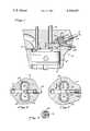
- FIG. 1is a diagrammatic representation of a diesel engine embodying the present invention.
- FIG. 2is a transverse section through the diesel engine of FIG. 1, taken on the line 2--2 of FIG. 1;
- FIG. 3is a view, similar to that of FIG. 2, showing an alternative form of the present invention.
- FIG. 4is a vertical section through the precombustion chamber of FIG. 3.
- a diesel engineis shown indicated generally at 2, having a piston 4 movable within a cylinder 6.
- the head 8 of the cylinder 6is formed with openings 10 and 12.
- Valve 14represents intake and/or exhaust valves which serve to close opening 10 and is operable, in a conventional manner, to permit intake of air and discharge of exhaust products.
- Isolation valve 16is seated in opening 12 and is operable to close opening 12 from the beginning of the exhaust stroke of piston 4 to near the end of the compression stroke. Opening 12 communicates, via throat 18, with precombustion chamber 20 and a suitable fuel injector 22 serves to deliver fuel into precombustion chamber 20, in a predetermined manner, for subsequent ignition by suitable means, such as glow plug 24.
- the precombustion chamber 20may be surrounded by a layer 26 of ceramic or other suitable thermal insulating material to retard heat loss from the precombustion chamber 20 and to maintain the temperature of the precombustion chamber in the range of about 400° F. to 1000° F., thereby enhancing vaporization of the fuel delivered by the injector 22.
- vanes 28 or the likemay be provided on the walls of the precombustion chamber 20 to further enhance thermal transfer to the fuel and, hence, to promote vaporization.
- heating meanssuch as electrical resistance wires 30 may be embedded in the walls of the precombustion chamber 20 and may be energized by a suitable source (not shown) to maintain the temperature of the precombustion chamber 20 within the desired range.
- the precombustion chamber 20is formed with two generally circular portions 32 and 34, separated by a generally rectangular portion, as indicated by dashed lines at 36 in FIG. 2.
- the portions 32 and 34are configured to promote mixing of the air entering the precombustion chamber 20 to further enhance mixing of the air with the prevaporized fuel.
- portions 32 and 34are shown as being generally circular, it will be understood that other configurations which promote mixing would be equally desirable.
- the rectangular portion 36provides an abrupt wall 38 directly in the path of the air entering precombustion chamber 20 through opening 12 and throat 18, and serves to establish a standing shock wave in the region of the rectangular portion 36 in front of wall 38. This shock wave contributes to rapid ignition of the vaporized fuel and aids in mixing the incoming air with the vaporized fuel.
- Throat 18forms the incoming air into a jet, which entrains the fuel vapors, enhances formation of the shock wave, and drives mixing action induced by portions 32 and 34.
- the shock wave formationmay be enhanced by elongating the rectangular portion 36 of the precombustion chamber, as seen at 40 in FIG. 3.
- isolation valve 16serves to close opening 12 from about the beginning of the exhaust stroke of piston 4 until near the end of the compression stroke. Shortly after valve 16 closes, fuel injector 22 sprays a predetermined amount of fuel into precombustion chamber 20. This fuel will be vaporized in the precombustion chamber 20 under controlled conditions of pressure and temperature and while isolated from the charge of air contained in cylinder 6. The vaporization takes place to a limited extent from heat transfer from the residual gases trapped in precombustion chamber 20, and to a much greater extent from heat transferred to the fuel from the hot walls and vanes 28 of the precombustion chamber 20.
- the precombustion chamber 20it is important to shape the precombustion chamber 20 and to direct the injector 22 so as to deposit the fuel on the walls of the precombustion chamber 20 and vanes 28 so as to form an evenly distributed thin film of fuel on these heated surfaces.
- the isolation valve 16After the isolation valve 16 has been opened, the highly compressed air from cylinder 6 rushes through opening 12 and throat 18 to form a jet which rapidly entrains the prevaporized fuel to form a combustible mixture.
- the contents of the precombustion chamber 20will expand back through opening 12 into cylinder 6 to drive piston 4 for the power stroke.
- the ignition and initial combustion of the fueltends to heat the walls of the precombustion chamber 20 and insulation 26 and this, together with heating wires 30 and the like, serves to maintain the temperature of the precombustion chamber 20 in the range of about 400° F. to 1200° F.
- valve 16recloses and the next charge of fuel is delivered into the precombustion chamber 20, the elevated temperature will promote vaporization of the fuel.
- valve 16opens and compressed air from cylinder 6 rushes through opening 12, is accelerated and formed into a jet by throat 18 and is directed against wall 38 to establish a standing shock wave in rectangular region 36 adjacent wall 38.
- the standing shock wave and glow plug 24promote ignition of the vaporized fuel which initially fills the precombustion chamber 20.
- the configurationcreates a shear layer between the fuel vapor and air jet, and induces swirling which enhances the mixing of the compressed air with the vaporized fuel which promotes more complete combustion of the fuel. This improved combustion provides increased fuel efficiency and yields significantly reduced particulate emissions.
Landscapes
- Engineering & Computer Science (AREA)
- Chemical & Material Sciences (AREA)
- Combustion & Propulsion (AREA)
- Mechanical Engineering (AREA)
- General Engineering & Computer Science (AREA)
- Ceramic Engineering (AREA)
- Combustion Methods Of Internal-Combustion Engines (AREA)
Abstract
Description
1. Field of the Invention
This invention relates to diesel engines and is particularly directed to means for enhancing fuel combustion in diesel engines.
2. Description of the Prior Art
In recent years, increasing concern over the limits of the world's petroleum reserves has caused increased interest in diesel engines due to their greater fuel efficiency over conventional internal combustion engines and their ability to burn alternative fuels. Unfortunately, diesel engines still fall far short of complete efficiency, and tend to outdo conventional engines in producing particulate emissions which contribute significantly to air pollution. Many attempts have been made to improve the efficiency of diesel engines and to decrease their production of pollutant emissions. However, none of the prior art techniques has been entirely satisfactory, and the search for improvement continues.
These disadvantages of the prior art are overcome with the present invention, and an improved diesel engine is provided having greatly improved combustion characteristics, thereby achieving substantially increased fuel efficiency and, at the same time, yielding significantly less particulate emissions. The advantages of the present invention are preferably attained by preheating and prevaporizing the fuel within the precombustion chamber, while isolating the precombustion chamber from the engine cylinder during a substantial portion of the engine cycle in order to maintain conditions of pressure and temperature most suitable for vaporization, admitting compressed air from the engine cylinder into the precombustion chamber near the end of the compression stroke of the piston, and shaping the precombustion chamber to enhance mixing of said compressed air with said preheated and vaporized fuel.
Accordingly, it is an object of the present invention to provide an improved diesel engine.
Another object of the present invention is to provide a diesel engine having improved combustion characteristics.
A further object of the present invention is to provide a diesel engine having improved fuel efficiency.
An additional object of the present invention is to provide a diesel engine having reduced particulate exhaust emissions.
A specific object of the present invention is to provide an improved diesel engine wherein fuel is preheated and vaporized within the precombustion chamber during a substantial portion of the engine cycle in which the precombustion chamber is isolated from the cylinder by an isolation valve. Compressed air from the engine cylinder is admitted to the precombustion chamber near the end of the compression stroke by the timed opening of the isolation valve. The precombustion chamber is shaped to enhance mixing of the compressed air with the preheated and vaporized fuel.
These and other objects and features of the present invention will be apparent from the following detailed description, taken with reference to the accompanying drawings.
FIG. 1 is a diagrammatic representation of a diesel engine embodying the present invention.
FIG. 2 is a transverse section through the diesel engine of FIG. 1, taken on the line 2--2 of FIG. 1;
FIG. 3 is a view, similar to that of FIG. 2, showing an alternative form of the present invention; and
FIG. 4 is a vertical section through the precombustion chamber of FIG. 3.
In that form of the present invention chosen for purposes of illustration in FIG. 1, a diesel engine is shown indicated generally at 2, having apiston 4 movable within acylinder 6. Thehead 8 of thecylinder 6 is formed withopenings opening 10 and is operable, in a conventional manner, to permit intake of air and discharge of exhaust products.Isolation valve 16 is seated inopening 12 and is operable to closeopening 12 from the beginning of the exhaust stroke ofpiston 4 to near the end of the compression stroke. Opening 12 communicates, via throat 18, withprecombustion chamber 20 and asuitable fuel injector 22 serves to deliver fuel intoprecombustion chamber 20, in a predetermined manner, for subsequent ignition by suitable means, such asglow plug 24.
As seen in FIGS. 1 and 2, theprecombustion chamber 20 may be surrounded by alayer 26 of ceramic or other suitable thermal insulating material to retard heat loss from theprecombustion chamber 20 and to maintain the temperature of the precombustion chamber in the range of about 400° F. to 1000° F., thereby enhancing vaporization of the fuel delivered by theinjector 22. If desired, vanes 28 or the like may be provided on the walls of theprecombustion chamber 20 to further enhance thermal transfer to the fuel and, hence, to promote vaporization. As an additional alternative, heating means such aselectrical resistance wires 30 may be embedded in the walls of theprecombustion chamber 20 and may be energized by a suitable source (not shown) to maintain the temperature of theprecombustion chamber 20 within the desired range.
As shown, theprecombustion chamber 20 is formed with two generallycircular portions portions precombustion chamber 20 to further enhance mixing of the air with the prevaporized fuel. Althoughportions abrupt wall 38 directly in the path of the air enteringprecombustion chamber 20 throughopening 12 and throat 18, and serves to establish a standing shock wave in the region of the rectangular portion 36 in front ofwall 38. This shock wave contributes to rapid ignition of the vaporized fuel and aids in mixing the incoming air with the vaporized fuel. Throat 18 forms the incoming air into a jet, which entrains the fuel vapors, enhances formation of the shock wave, and drives mixing action induced byportions
In use,isolation valve 16 serves to closeopening 12 from about the beginning of the exhaust stroke ofpiston 4 until near the end of the compression stroke. Shortly aftervalve 16 closes,fuel injector 22 sprays a predetermined amount of fuel intoprecombustion chamber 20. This fuel will be vaporized in theprecombustion chamber 20 under controlled conditions of pressure and temperature and while isolated from the charge of air contained incylinder 6. The vaporization takes place to a limited extent from heat transfer from the residual gases trapped inprecombustion chamber 20, and to a much greater extent from heat transferred to the fuel from the hot walls andvanes 28 of theprecombustion chamber 20. For this reason, it is important to shape theprecombustion chamber 20 and to direct theinjector 22 so as to deposit the fuel on the walls of theprecombustion chamber 20 and vanes 28 so as to form an evenly distributed thin film of fuel on these heated surfaces. After theisolation valve 16 has been opened, the highly compressed air fromcylinder 6 rushes through opening 12 and throat 18 to form a jet which rapidly entrains the prevaporized fuel to form a combustible mixture. After ignition and combustion have been initiated, the contents of theprecombustion chamber 20 will expand back through opening 12 intocylinder 6 to drivepiston 4 for the power stroke. Obviously, the ignition and initial combustion of the fuel tends to heat the walls of theprecombustion chamber 20 andinsulation 26 and this, together withheating wires 30 and the like, serves to maintain the temperature of theprecombustion chamber 20 in the range of about 400° F. to 1200° F. Thus, whenvalve 16 recloses and the next charge of fuel is delivered into theprecombustion chamber 20, the elevated temperature will promote vaporization of the fuel.
Near the end of the compression stroke ofpiston 4,valve 16 opens and compressed air fromcylinder 6 rushes throughopening 12, is accelerated and formed into a jet by throat 18 and is directed againstwall 38 to establish a standing shock wave in rectangular region 36adjacent wall 38. The standing shock wave andglow plug 24 promote ignition of the vaporized fuel which initially fills theprecombustion chamber 20. The configuration creates a shear layer between the fuel vapor and air jet, and induces swirling which enhances the mixing of the compressed air with the vaporized fuel which promotes more complete combustion of the fuel. This improved combustion provides increased fuel efficiency and yields significantly reduced particulate emissions.
Numerous variations and modifications may be made without departing from the present invention. Accordingly, it should be clearly understood that the form of the present invention described above and shown in the accompanying drawings are illustrative only and are not intended to limit the scope of the present invention.
Claims (9)
1. A diesel engine comprising:
a cylinder;
a piston slidable within said cylinder;
a precombustion chamber having a generally rectangular portion located in the path of air entering said chamber, and a pair of generally circular portions located on opposite sides of said rectangular portion;
an opening communicating said rectangular portion of said precombustion chamber with said cylinder;
valve means operable near the beginning of the exhaust stroke of said piston to close said opening;
fuel injector means for delivering fuel into said precombustion chamber shortly after closing of said valve means; and
means for actuating said valve means near the end of the compression stroke of said piston to open said opening to allow compressed air from said cylinder to rush into said rectangular portion of said precombustion chamber.
2. A diesel engine of claim 1 further comprising thermal stabilization means for maintaining the temperature in said precombustion chamber in the range of 400° F. to 1200° F.
3. The diesel engine of claim 2 wherein said thermal stabilization means is a layer of insulating material surrounding said precombustion chamber.
4. The diesel engine of claim 2 wherein said thermal stabilization means is electrical wires embedded in the walls of said precombustion chamber.
5. The diesel engine of claim 1 further comprising a plurality of protuberances projecting into said precombustion chamber to enhance thermal transfer to fuel in said precombustion chamber.
6. The diesel engine of claim 5 wherein said protuberances are vanes.
7. The diesel engine of claim 1 wherein said precombustion chamber is formed to cause swirling of air entering said chamber to enhance vaporization of fuel within said chamber and mixing of said air with said fuel.
8. The diesel engine of claim 1 further comprising throat means connecting said precombustion chamber with said opening and serving to accelerate the flow of air entering said opening and to form said flow into a jet.
9. The diesel engine of claim 1 further comprising an abrupt wall positioned in said precombustion chamber in the path of air entering from said opening.
Priority Applications (7)
| Application Number | Priority Date | Filing Date | Title |
|---|---|---|---|
| US06/164,395US4300497A (en) | 1980-06-30 | 1980-06-30 | Prevaporizing diesel precombustion chamber |
| FR8105667AFR2485626B1 (en) | 1980-06-30 | 1981-03-20 | DIESEL ENGINE WITH PRECOMBUSTION CHAMBER AND METHOD FOR IMPLEMENTING SAME |
| SE8101907ASE8101907L (en) | 1980-06-30 | 1981-03-25 | Diesel engine with combustion chamber |
| GB8114748AGB2079365B (en) | 1980-05-23 | 1981-05-14 | Diesel engine with precombustion chamber |
| SE8103227ASE8103227L (en) | 1980-06-30 | 1981-05-21 | FRONT ROOMS FOR DIESEL ENGINE |
| DE19813125467DE3125467A1 (en) | 1980-06-30 | 1981-06-29 | DIESEL ENGINE CHAMBER WITH PRE-EVAPORATION |
| JP56100772AJPS5749015A (en) | 1980-06-30 | 1981-06-30 | Preheating chamber for prevaporazing diesel |
Applications Claiming Priority (1)
| Application Number | Priority Date | Filing Date | Title |
|---|---|---|---|
| US06/164,395US4300497A (en) | 1980-06-30 | 1980-06-30 | Prevaporizing diesel precombustion chamber |
Publications (1)
| Publication Number | Publication Date |
|---|---|
| US4300497Atrue US4300497A (en) | 1981-11-17 |
Family
ID=22594292
Family Applications (1)
| Application Number | Title | Priority Date | Filing Date |
|---|---|---|---|
| US06/164,395Expired - LifetimeUS4300497A (en) | 1980-05-23 | 1980-06-30 | Prevaporizing diesel precombustion chamber |
Country Status (5)
| Country | Link |
|---|---|
| US (1) | US4300497A (en) |
| JP (1) | JPS5749015A (en) |
| DE (1) | DE3125467A1 (en) |
| FR (1) | FR2485626B1 (en) |
| SE (2) | SE8101907L (en) |
Cited By (41)
| Publication number | Priority date | Publication date | Assignee | Title |
|---|---|---|---|---|
| US4332224A (en)* | 1977-04-09 | 1982-06-01 | Robert Bosch Gmbh | Internal combustion engine with a main combustion chamber and an ignition chamber |
| US4361122A (en)* | 1979-12-19 | 1982-11-30 | Robert Bosch Gmbh | Internal combustion engine with externally-supplied ignition, having one main combustion chamber per cylinder and one ignition chamber |
| US4424780A (en) | 1979-12-26 | 1984-01-10 | Trucco Horacio A | Internal combustion engine for diverse fuels |
| DE3307666A1 (en)* | 1983-03-04 | 1984-09-06 | Robert Bosch Gmbh, 7000 Stuttgart | Device for the injection of fuel into combustion chambers, especially combustion chambers of diesel engines |
| US4522171A (en)* | 1982-06-18 | 1985-06-11 | Feldmuhle Aktiengesellschaft | Pre-combustion or turbulence chamber for internal combustion engines |
| US4577600A (en)* | 1983-10-06 | 1986-03-25 | Mazda Motor Corporation | Structure of divided combustion chamber for diesel engine |
| EP0216027A1 (en)* | 1985-06-28 | 1987-04-01 | Yugen Kaisha Hareyama Jiko | Internal combustion engine |
| EP0159195A3 (en)* | 1984-04-17 | 1987-12-09 | Phillip Howard Oxley | A combustion engine fuel delivery system |
| US4722309A (en)* | 1981-04-29 | 1988-02-02 | Laerte Guidoboni | Internal combustion engine |
| US4738227A (en)* | 1986-02-21 | 1988-04-19 | Adiabatics, Inc. | Thermal ignition combustion system |
| EP0317382A1 (en)* | 1987-11-16 | 1989-05-24 | Automobiles Peugeot | Compression ignition engine having a prechamber with heated ceramic walls |
| US4846125A (en)* | 1986-10-24 | 1989-07-11 | Kabushiki Kaisha Hareyama Giken | Internal combustion engine |
| US4854281A (en)* | 1987-01-21 | 1989-08-08 | Kabushiki Kaisha Hareyama Giken | Internal combustion engine |
| EP0366490A3 (en)* | 1988-10-28 | 1991-01-02 | Isuzu Motors Limited | Heat-insulating engine with swirl chamber |
| US5067458A (en)* | 1989-03-27 | 1991-11-26 | Caterpillar Inc. | Fuel combustion system and method of operation for an otto-cycle internal combustion engine |
| US5163385A (en)* | 1992-03-12 | 1992-11-17 | The United States Of America As Represented By The United States Department Of Energy | Coal-water slurry fuel internal combustion engine and method for operating same |
| US5178109A (en)* | 1991-03-14 | 1993-01-12 | Isuzu Motors Limited | Heat-insulating engine with swirl chambers |
| EP0588592A1 (en)* | 1992-09-14 | 1994-03-23 | Isuzu Ceramics Research Institute Co., Ltd. | High compression ration internal-combustion engine |
| US5329901A (en)* | 1990-06-04 | 1994-07-19 | Nippon Clean Engine Research Institute Co., Ltd. | Hot surface impact ignition type internal combustion engine and method of hot surface impact ignition |
| EP0588593A3 (en)* | 1992-09-14 | 1994-08-03 | Isuzu Ceramics Res Inst | |
| WO1996034189A1 (en)* | 1995-04-28 | 1996-10-31 | Perkins Limited | An internal combustion engine including a fuel vaporising chamber |
| US5603298A (en)* | 1992-09-14 | 1997-02-18 | Isuzu Ceramics Research Institute Co., Ltd. | High compression ratio internal-combustion engine |
| WO1997049907A1 (en)* | 1996-06-22 | 1997-12-31 | Motoren-Werke Mannheim Aktiengesellschaft | Ignition system for a gas engine |
| AT410007B (en)* | 1997-10-08 | 2003-01-27 | Jenbacher Ag | Ignition device |
| US20070144459A1 (en)* | 2005-12-27 | 2007-06-28 | Fiveland Scott B | Compression ignition initiation device and internal combustion engine using same |
| KR100899557B1 (en)* | 2000-03-09 | 2009-05-27 | 마이클 패트릭 딕손 | An autoignition engine |
| US20120048235A1 (en)* | 2010-08-26 | 2012-03-01 | Eitan Leaschauer | Leaschauer Engine |
| US20140182558A1 (en)* | 2010-08-26 | 2014-07-03 | Eitan Leaschauer | Leaschauer Engine |
| US20140360456A1 (en)* | 2013-06-05 | 2014-12-11 | Pratt & Whitney Canada Corp. | Rotary Internal Combustion Engine With Pilot Subchamber And Ignition Element |
| US20150020766A1 (en)* | 2013-07-19 | 2015-01-22 | Cummings Inc. | Prechamber device for an internal combustion engine |
| US20160363041A1 (en)* | 2015-06-15 | 2016-12-15 | Caterpillar Inc. | Combustion Pre-Chamber Assembly Including Fluidic Oscillator |
| US9567895B2 (en)* | 2010-08-26 | 2017-02-14 | Eitan Leaschauer | Leaschauer engine |
| WO2017184610A1 (en)* | 2016-04-19 | 2017-10-26 | Board Of Trustees Of Michigan State University | Internal combustion engine |
| US9803536B2 (en)* | 2013-11-13 | 2017-10-31 | Denso Corporation | Auxiliary chamber type internal combustion engine |
| DE102016012319A1 (en) | 2016-10-15 | 2018-04-19 | Audi Ag | Internal combustion engine |
| US20180313256A1 (en)* | 2015-10-21 | 2018-11-01 | Mtu Friedrichshafen Gmbh | Prechamber for an internal combustion engine, internal combustion engine comprising a prechamber of this type and method for designing and/or producing a prechamber of this type |
| US10161296B2 (en) | 2012-11-27 | 2018-12-25 | Board Of Trustees Of Michigan State University | Internal combustion engine |
| US11187142B2 (en) | 2017-08-01 | 2021-11-30 | Board Of Trustees Of Michigan State University | Diesel engine with turbulent jet ignition |
| US11408329B2 (en)* | 2019-12-19 | 2022-08-09 | Board Of Trustees Of Michigan State University | Engine turbulent jet ignition system |
| US11939905B2 (en) | 2020-05-20 | 2024-03-26 | Board Of Trustees Of Michigan State University | Internal combustion engine including multiple fuel injections external to a pre-chamber |
| US12241390B2 (en) | 2021-07-30 | 2025-03-04 | Board Of Trustees Of Michigan State University | Actuation system for an internal combustion engine |
Families Citing this family (2)
| Publication number | Priority date | Publication date | Assignee | Title |
|---|---|---|---|---|
| JPS61138819A (en)* | 1984-12-07 | 1986-06-26 | Haruyama Jikou:Kk | Fuel feed carburetion device |
| AU9150991A (en)* | 1991-01-22 | 1992-09-07 | Viktor Veniaminovich Zherebtsov | One-cycle engine |
Citations (7)
| Publication number | Priority date | Publication date | Assignee | Title |
|---|---|---|---|---|
| US1134858A (en)* | 1914-11-30 | 1915-04-06 | R M Hvid Company | Means for delivering oil to oil-burning engines. |
| US1550104A (en)* | 1923-03-23 | 1925-08-18 | George A Schwer | Oil-burning engine |
| US2305791A (en)* | 1938-01-05 | 1942-12-22 | Maruhn Herbert | Diesel engine |
| US2456080A (en)* | 1944-11-20 | 1948-12-14 | Pe Wu | Ignition plug |
| US3140697A (en)* | 1959-12-28 | 1964-07-14 | Renault | Compression ignition engines |
| US3809030A (en)* | 1971-01-18 | 1974-05-07 | A Moiroux | Internal combustion engines |
| US3911878A (en)* | 1973-04-26 | 1975-10-14 | Volkswagenwerk Ag | Internal combustion engine having continuous combustion |
Family Cites Families (10)
| Publication number | Priority date | Publication date | Assignee | Title |
|---|---|---|---|---|
| FR909893A (en)* | ||||
| US1682305A (en)* | 1928-08-28 | Intebnal-combttstion engine and method fob opebating sake | ||
| FR625343A (en)* | 1926-03-15 | 1927-08-08 | Fuel Supply Method for Heavy Oil Engines | |
| FR644000A (en)* | 1927-11-05 | 1928-09-29 | Method and device for the atonization of fuel in self-igniting engines | |
| FR46220E (en)* | 1934-12-20 | 1936-04-02 | Improvement in explosion engines | |
| FR945255A (en)* | 1947-04-17 | 1949-04-29 | Separately charged internal combustion engine | |
| FR1035955A (en)* | 1951-04-20 | 1953-09-02 | Low pressure injection device for internal combustion engine | |
| GB1380941A (en)* | 1971-05-20 | 1975-01-22 | Vincent P C | Internal combustion engines |
| DE2530837A1 (en)* | 1975-07-10 | 1977-01-13 | Heinrich Roessel | Heated reaction chamber for engine - has liquid fuel injected for part combustion with air and exhaust gas mixture |
| FR2342399A1 (en)* | 1976-02-24 | 1977-09-23 | Chrysler France | Automobile diesel engine with swirl chamber - has poppet valve closing passage between cylinder and swirl chamber and operated by camshaft near end of compression stroke |
- 1980
- 1980-06-30USUS06/164,395patent/US4300497A/ennot_activeExpired - Lifetime
- 1981
- 1981-03-20FRFR8105667Apatent/FR2485626B1/ennot_activeExpired
- 1981-03-25SESE8101907Apatent/SE8101907L/ennot_activeApplication Discontinuation
- 1981-05-21SESE8103227Apatent/SE8103227L/ennot_activeApplication Discontinuation
- 1981-06-29DEDE19813125467patent/DE3125467A1/ennot_activeWithdrawn
- 1981-06-30JPJP56100772Apatent/JPS5749015A/enactivePending
Patent Citations (7)
| Publication number | Priority date | Publication date | Assignee | Title |
|---|---|---|---|---|
| US1134858A (en)* | 1914-11-30 | 1915-04-06 | R M Hvid Company | Means for delivering oil to oil-burning engines. |
| US1550104A (en)* | 1923-03-23 | 1925-08-18 | George A Schwer | Oil-burning engine |
| US2305791A (en)* | 1938-01-05 | 1942-12-22 | Maruhn Herbert | Diesel engine |
| US2456080A (en)* | 1944-11-20 | 1948-12-14 | Pe Wu | Ignition plug |
| US3140697A (en)* | 1959-12-28 | 1964-07-14 | Renault | Compression ignition engines |
| US3809030A (en)* | 1971-01-18 | 1974-05-07 | A Moiroux | Internal combustion engines |
| US3911878A (en)* | 1973-04-26 | 1975-10-14 | Volkswagenwerk Ag | Internal combustion engine having continuous combustion |
Cited By (58)
| Publication number | Priority date | Publication date | Assignee | Title |
|---|---|---|---|---|
| US4332224A (en)* | 1977-04-09 | 1982-06-01 | Robert Bosch Gmbh | Internal combustion engine with a main combustion chamber and an ignition chamber |
| US4361122A (en)* | 1979-12-19 | 1982-11-30 | Robert Bosch Gmbh | Internal combustion engine with externally-supplied ignition, having one main combustion chamber per cylinder and one ignition chamber |
| US4424780A (en) | 1979-12-26 | 1984-01-10 | Trucco Horacio A | Internal combustion engine for diverse fuels |
| US4722309A (en)* | 1981-04-29 | 1988-02-02 | Laerte Guidoboni | Internal combustion engine |
| US4522171A (en)* | 1982-06-18 | 1985-06-11 | Feldmuhle Aktiengesellschaft | Pre-combustion or turbulence chamber for internal combustion engines |
| WO1984000994A1 (en)* | 1982-09-07 | 1984-03-15 | Horacio Andres Trucco | Internal combustion engine for diverse fuels |
| DE3307666A1 (en)* | 1983-03-04 | 1984-09-06 | Robert Bosch Gmbh, 7000 Stuttgart | Device for the injection of fuel into combustion chambers, especially combustion chambers of diesel engines |
| US4577600A (en)* | 1983-10-06 | 1986-03-25 | Mazda Motor Corporation | Structure of divided combustion chamber for diesel engine |
| US4651692A (en)* | 1983-10-06 | 1987-03-24 | Ngk Insulators, Ltd. | Structure of divided combustion chamber for diesel engine |
| EP0159195A3 (en)* | 1984-04-17 | 1987-12-09 | Phillip Howard Oxley | A combustion engine fuel delivery system |
| EP0216027A1 (en)* | 1985-06-28 | 1987-04-01 | Yugen Kaisha Hareyama Jiko | Internal combustion engine |
| US4738227A (en)* | 1986-02-21 | 1988-04-19 | Adiabatics, Inc. | Thermal ignition combustion system |
| EP0330798A1 (en)* | 1986-10-24 | 1989-09-06 | Kabushiki Kaisha Hareyama Giken | Internal combustion engine |
| US4846125A (en)* | 1986-10-24 | 1989-07-11 | Kabushiki Kaisha Hareyama Giken | Internal combustion engine |
| AU609449B2 (en)* | 1986-10-24 | 1991-05-02 | Kabushiki Kaisha Hareyama Giken | Internal combustion engine |
| US4854281A (en)* | 1987-01-21 | 1989-08-08 | Kabushiki Kaisha Hareyama Giken | Internal combustion engine |
| AU609442B2 (en)* | 1987-01-21 | 1991-05-02 | Kabushiki Kaisha Hareyama Giken | Internal combustion engine |
| EP0317382A1 (en)* | 1987-11-16 | 1989-05-24 | Automobiles Peugeot | Compression ignition engine having a prechamber with heated ceramic walls |
| EP0366490A3 (en)* | 1988-10-28 | 1991-01-02 | Isuzu Motors Limited | Heat-insulating engine with swirl chamber |
| US5054443A (en)* | 1988-10-28 | 1991-10-08 | Isuzu Motors Limited | Heat-insulating engine with swirl chamber |
| US5067458A (en)* | 1989-03-27 | 1991-11-26 | Caterpillar Inc. | Fuel combustion system and method of operation for an otto-cycle internal combustion engine |
| US5329901A (en)* | 1990-06-04 | 1994-07-19 | Nippon Clean Engine Research Institute Co., Ltd. | Hot surface impact ignition type internal combustion engine and method of hot surface impact ignition |
| US5178109A (en)* | 1991-03-14 | 1993-01-12 | Isuzu Motors Limited | Heat-insulating engine with swirl chambers |
| US5163385A (en)* | 1992-03-12 | 1992-11-17 | The United States Of America As Represented By The United States Department Of Energy | Coal-water slurry fuel internal combustion engine and method for operating same |
| US5603298A (en)* | 1992-09-14 | 1997-02-18 | Isuzu Ceramics Research Institute Co., Ltd. | High compression ratio internal-combustion engine |
| EP0588592A1 (en)* | 1992-09-14 | 1994-03-23 | Isuzu Ceramics Research Institute Co., Ltd. | High compression ration internal-combustion engine |
| EP0588593A3 (en)* | 1992-09-14 | 1994-08-03 | Isuzu Ceramics Res Inst | |
| US5454356A (en)* | 1992-09-14 | 1995-10-03 | Isuzu Ceramics Research Institute Co., Ltd. | Engine with pre-chamber |
| WO1996034189A1 (en)* | 1995-04-28 | 1996-10-31 | Perkins Limited | An internal combustion engine including a fuel vaporising chamber |
| WO1997049907A1 (en)* | 1996-06-22 | 1997-12-31 | Motoren-Werke Mannheim Aktiengesellschaft | Ignition system for a gas engine |
| US6129069A (en)* | 1996-06-22 | 2000-10-10 | Motoren-Werke Mannheim Ag | Ignition system for a gas engine |
| AT410007B (en)* | 1997-10-08 | 2003-01-27 | Jenbacher Ag | Ignition device |
| KR100899557B1 (en)* | 2000-03-09 | 2009-05-27 | 마이클 패트릭 딕손 | An autoignition engine |
| US20070144459A1 (en)* | 2005-12-27 | 2007-06-28 | Fiveland Scott B | Compression ignition initiation device and internal combustion engine using same |
| US7398743B2 (en)* | 2005-12-27 | 2008-07-15 | Caterpillar Inc. | Compression ignition initiation device and internal combustion engine using same |
| US9567895B2 (en)* | 2010-08-26 | 2017-02-14 | Eitan Leaschauer | Leaschauer engine |
| US9371770B2 (en)* | 2010-08-26 | 2016-06-21 | Eitan Leaschauer | Leaschauer engine |
| US20120048235A1 (en)* | 2010-08-26 | 2012-03-01 | Eitan Leaschauer | Leaschauer Engine |
| US20140182558A1 (en)* | 2010-08-26 | 2014-07-03 | Eitan Leaschauer | Leaschauer Engine |
| US10161296B2 (en) | 2012-11-27 | 2018-12-25 | Board Of Trustees Of Michigan State University | Internal combustion engine |
| US10006359B2 (en)* | 2013-06-05 | 2018-06-26 | Pratt & Whitney Canada Corp. | Rotary internal combustion engine with pilot subchamber and ignition element |
| US20140360456A1 (en)* | 2013-06-05 | 2014-12-11 | Pratt & Whitney Canada Corp. | Rotary Internal Combustion Engine With Pilot Subchamber And Ignition Element |
| US9334794B2 (en)* | 2013-06-05 | 2016-05-10 | Pratt & Whitney Canada Corp. | Rotary internal combustion engine with pilot subchamber and ignition element |
| US20160245165A1 (en)* | 2013-06-05 | 2016-08-25 | Pratt & Whitney Canada Corp. | Rotary internal combustion engine with pilot subchamber and ignition element |
| US10458325B2 (en) | 2013-06-05 | 2019-10-29 | Pratt & Whitney Canada Corp. | Rotary internal combustion engine with pilot subchamber and ignition element |
| US10968820B2 (en) | 2013-06-05 | 2021-04-06 | Pratt & Whitney Canada Corp. | Method of combusting fuel in a rotary internal combustion engine with pilot subchamber and ignition element |
| US20150020766A1 (en)* | 2013-07-19 | 2015-01-22 | Cummings Inc. | Prechamber device for an internal combustion engine |
| US9803536B2 (en)* | 2013-11-13 | 2017-10-31 | Denso Corporation | Auxiliary chamber type internal combustion engine |
| US20160363041A1 (en)* | 2015-06-15 | 2016-12-15 | Caterpillar Inc. | Combustion Pre-Chamber Assembly Including Fluidic Oscillator |
| US20180313256A1 (en)* | 2015-10-21 | 2018-11-01 | Mtu Friedrichshafen Gmbh | Prechamber for an internal combustion engine, internal combustion engine comprising a prechamber of this type and method for designing and/or producing a prechamber of this type |
| US10563568B2 (en)* | 2015-10-21 | 2020-02-18 | Mtu Friedrichshafen Gmbh | Prechamber for an internal combustion engine, internal combustion engine comprising a prechamber of this type and method for designing and/or producing a prechamber of this type |
| WO2017184610A1 (en)* | 2016-04-19 | 2017-10-26 | Board Of Trustees Of Michigan State University | Internal combustion engine |
| DE102016012319A1 (en) | 2016-10-15 | 2018-04-19 | Audi Ag | Internal combustion engine |
| DE102016012319B4 (en)* | 2016-10-15 | 2020-01-30 | Audi Ag | Internal combustion engine |
| US11187142B2 (en) | 2017-08-01 | 2021-11-30 | Board Of Trustees Of Michigan State University | Diesel engine with turbulent jet ignition |
| US11408329B2 (en)* | 2019-12-19 | 2022-08-09 | Board Of Trustees Of Michigan State University | Engine turbulent jet ignition system |
| US11939905B2 (en) | 2020-05-20 | 2024-03-26 | Board Of Trustees Of Michigan State University | Internal combustion engine including multiple fuel injections external to a pre-chamber |
| US12241390B2 (en) | 2021-07-30 | 2025-03-04 | Board Of Trustees Of Michigan State University | Actuation system for an internal combustion engine |
Also Published As
| Publication number | Publication date |
|---|---|
| FR2485626B1 (en) | 1987-02-06 |
| JPS5749015A (en) | 1982-03-20 |
| DE3125467A1 (en) | 1982-04-15 |
| SE8101907L (en) | 1981-12-31 |
| SE8103227L (en) | 1981-12-31 |
| FR2485626A1 (en) | 1981-12-31 |
Similar Documents
| Publication | Publication Date | Title |
|---|---|---|
| US4300497A (en) | Prevaporizing diesel precombustion chamber | |
| US6981484B2 (en) | Internal combustion engine with divided combustion chamber | |
| JP3181908B2 (en) | Piston for controlling ignition combustion of hydrocarbon fuel in internal combustion engine by controlling generation of nuclei of fuel particles and method therefor | |
| US5119780A (en) | Staged direct injection diesel engine | |
| US5067458A (en) | Fuel combustion system and method of operation for an otto-cycle internal combustion engine | |
| US3266234A (en) | Compression ignition engine and method of operating same | |
| JPS6022170B2 (en) | Combustion accelerator for multi-cylinder internal combustion engines | |
| US2741230A (en) | Method of operating an internal combustion engine | |
| AU2002363662A1 (en) | An internal combusion engine with divided combustion chamber | |
| JPS55119911A (en) | Combustion chamber of compression firing internal combustion engine | |
| JP4242773B2 (en) | Valve controlled split chamber internal combustion engine | |
| US4342300A (en) | Stratified charge engine with charge preparation means | |
| US2652039A (en) | Supply system for combustible mixture for internal-combustion engines | |
| US5325824A (en) | Split cycle internal combustion engine | |
| GB2079365A (en) | Diesel engine with precombustion chamber | |
| US5477822A (en) | Spark ignition engine with cylinder head combustion chamber | |
| GB2079850A (en) | Diesel engine with precombustion chamber | |
| US2021744A (en) | Internal-combustion engine of the fuel-injection type | |
| JPS5499817A (en) | Internal combustion engine having heat exchangeable storage chamber | |
| US6073604A (en) | Combustion chamber structure of a gas engine | |
| WO1983000529A1 (en) | Internal combustion engine | |
| JPH06229320A (en) | Direct injection-type high compression ratio gas engine | |
| JPS62253920A (en) | In-cylinder injection internal combustion engine | |
| JPH07293344A (en) | Thermal insulation type gas engine | |
| GB2163486A (en) | Fuel injection i.c. engine |
Legal Events
| Date | Code | Title | Description |
|---|---|---|---|
| AS | Assignment | Owner name:ROCKWELL INTERNATIONAL CORPORATION Free format text:ASSIGNMENT OF ASSIGNORS INTEREST.;ASSIGNOR:WEBBER WILLIAM T.;REEL/FRAME:003849/0425 Effective date:19800627 Owner name:ROCKWELL INTERNATIONAL CORPORATION, CALIFORNIA Free format text:ASSIGNMENT OF ASSIGNORS INTEREST;ASSIGNOR:WEBBER WILLIAM T.;REEL/FRAME:003849/0425 Effective date:19800627 | |
| STCF | Information on status: patent grant | Free format text:PATENTED CASE |