US4289019A - Method and means of passive detection of leaks in buried pipes - Google Patents
Method and means of passive detection of leaks in buried pipesDownload PDFInfo
- Publication number
- US4289019A US4289019AUS06/089,346US8934679AUS4289019AUS 4289019 AUS4289019 AUS 4289019AUS 8934679 AUS8934679 AUS 8934679AUS 4289019 AUS4289019 AUS 4289019A
- Authority
- US
- United States
- Prior art keywords
- location
- leak
- acoustic waves
- correlation
- detectors
- Prior art date
- Legal status (The legal status is an assumption and is not a legal conclusion. Google has not performed a legal analysis and makes no representation as to the accuracy of the status listed.)
- Expired - Lifetime
Links
Images


Classifications
- G—PHYSICS
- G01—MEASURING; TESTING
- G01M—TESTING STATIC OR DYNAMIC BALANCE OF MACHINES OR STRUCTURES; TESTING OF STRUCTURES OR APPARATUS, NOT OTHERWISE PROVIDED FOR
- G01M3/00—Investigating fluid-tightness of structures
- G01M3/02—Investigating fluid-tightness of structures by using fluid or vacuum
- G01M3/04—Investigating fluid-tightness of structures by using fluid or vacuum by detecting the presence of fluid at the leakage point
- G01M3/24—Investigating fluid-tightness of structures by using fluid or vacuum by detecting the presence of fluid at the leakage point using infrasonic, sonic, or ultrasonic vibrations
- G01M3/243—Investigating fluid-tightness of structures by using fluid or vacuum by detecting the presence of fluid at the leakage point using infrasonic, sonic, or ultrasonic vibrations for pipes
Definitions
- This inventionrelates to the detection of leaks in pipes.
- this inventionis a method and means of detecting the location of a leak in a buried pipe containing a fluid by analysis of the acoustical signals produced in the pipe or the fluid by the leak.
- Various types of active acoustic systemsserve to detect leaks by exciting acoustic waves in the pipe or in the fluid conveyed in the pipe.
- Acoustic detectorsare placed to detect signals produced by the discontinuities at the leak, either by responding to reflections generated by the discontinuity or by detecting differences produced in transmitted signals by the discontinuity in the pipe.
- Such systemsgenerally require substantial breaks in the pipes to generate signals that are large enough to be detected in the presence of the exciting signals.
- Leaks in buried pipes carrying or containing fluidsare detected by a passive system that responds to acoustic signals generated by the leak.
- a detector of longitudinal or torsional acoustic signalsis placed at a first location and a second detector of longitudinal or torsional acoustic signals is placed at a location on the other side of the leak.
- a radio broadcasting systemis used to couple the signals detected by the two detectors to a single location for application to an apparatus for measuring the correlation between the two signals.
- the cross-correlogram of the two signalsprovides a measure of the distance of the leak from each of the two measuring points and hence of the location of the leak.
- a detector of longitudinal acoustic signals and a detector of transverse acoustic signalsare placed at the same location.
- a combination of the cross-correlogram of the two signals with the known differences in the velocity of propagation of longitudinal and transverse signalsprovides a measure of the distance of the leak from the measuring point. Signals may propagate either in the fluid or in the pipe.
- FIG. 1is a block diagram of an apparatus for the practice of the invention on a buried pipe having a leak.
- FIG. 2is a top view of a coated pipe showing the placement of detectors for the practice of the present invention.
- FIG. 3is a side view of the pipe of FIG. 2 showing placement of the detectors.
- FIG. 4is a block diagram showing the placement of detectors at a single location for the practice of an alternate embodiment of the invention.
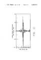
- FIG. 5is a plot of an observed correlation coefficient as a function of time delay.
- FIG. 6is an expanded view of a portion of the plot of FIG. 5.
- FIG. 1is a block diagram of an apparatus for the practice of the present invention.
- a leak 10 in a buried pipe 12is located at a distance from a manhole 14 and a borehole 16 that has been sunk from the surface 18 to the pipe 12 to provide a measuring point.
- the manhole 14 and borehole 16have been shown for illustration. It is evident that what is important is access to the pipe 12. If manholes were located conveniently then two manholes could be used or in the absence of conveniently located manholes it might be necessary to use two boreholes.
- a transducer 20is connected and coupled acoustically to pipe 12 in manhole 14 and another transducer 22 is connected to pipe 12 and coupled acoustically to it in borehole 16.
- the transducers 20 and 22may be coupled to torsional waves or to longitudinal waves in the pipe 12. While the preferred mode of operation is to couple both transducers 20 and 22 to the same form of wave, it is also possible to couple one of the transducers 20 and 22 to a longitudinal wave and the other to a torsional wave.
- the form of the couplingis a matter of choice for the operator and will normally be made so as to detect the strongest signal.
- the inventionworks because leaks generate noise in the pipe, the fluid or both.
- the term "noise”is here taken to refer to a signal that is substantially random in time although not necessarily completely random. Such a signal is describable by its spectrum.
- Two detected signals that are generated by the same leakwill exhibit a cross-correlogram that can be interpreted to locate the leak.
- the cross-correlationis determined by the circuit of FIG. 1 in which the measuring equipment 24 is located near manhole 14.
- An acoustical signal that is detected by transducer 22is there converted to an electrical signal that is amplified in preamplifier 26 and is amplified again as desired in a variable post-amplifier 28.
- the amplified signal from post-amplifier 28is coupled to a radio transmitter 30 that must be capable of broadcasting a signal with a bandwidth of 7 kHz through a transmitting antenna 31 to a receiving antenna 32, thence to a receiver 33.
- the signal received by receiver 33is applied to a bandpass filter 34 that passes frequencies in the range of 3 to 4 kHz.
- the output of bandpass filter 34is connected to highpass filter 36 which passes frequencies above 150 Hz.
- transducer 20receives a signal in manhole 14 and generates an electrical signal that is coupled to preamplifier 38.
- the output of preamplifier 38is connected to bandpass filter 40 which passes frequencies in the range of 3 to 4 kHz.
- bandpass filterThe output of bandpass filter is amplified as necessary in variable post-amplifier 42, and the amplified signal from post-amplifier 42 is applied to highpass filter 44 which passes frequencies above 150 Hz.
- the output signals from highpass filters 36 and 44are applied to cross-correlator 46 to generate a cross-correlogram that is made visible on display device 48.
- the cross-correlogram of two signalsis defined as a plot of the cross-correlation coefficient of the two signals as a function of the time delay between the signals.
- FIGS. 2 and 3are views of a coated pipe showing the placement of detectors for the practice of the present invention.
- FIG. 2is a top view and FIG. 3 is a side view of the same pipe.
- pipe 12is a carrier of a liquid such as fuel oil or a gas such as natural gas, or it may be an electrical conduit that includes a power line and an insulating fluid under pressure.
- tar coating 54When such a pipe 12 is buried underground, it is desirable to protect the outer surface by some means such as tar coating 54.
- a coupling block 58is placed against surface 56 in acoustical contact with surface 56 and an accelerometer is connected to coupling block 58 to convert acoustical signals into electrical signals.
- accelerometer 60is connected to coupling block 58 in such a way as to detect longitudinal acoustical waves in pipe 12 and accelerometer 62 is connected to respond to torsional acoustic waves in pipe 12.
- the accelerometers 60 and 62 of FIGS. 2 and 3could both be placed to respond either to longitudinal or torsional waves and that when they are placed on opposite sides of a suspected leak as shown in FIG.
- FIG. 4is a block diagram of an alternate embodiment of the invention.
- a leak 70produces noise in the fluid in a pipe 72.
- a longitudinal-wave tranducer 74 and a torsional-wave tranducer 76are located together on the pipe 72 with access through a single manhole or borehole.
- the signal from longitudinal-wave transducer 74is amplified in preamplifier 78, filtered in bandpass filter 80 and fed to variable post-amplifier 82.
- the amplified signal from post-amplifier 82is applied through highpass filter 84 to correlator 85.
- the output of torsional-wave tranducer 76is amplified in preamplifier 86 and applied to bandpass filter 88.
- bandpass filter 88The output of bandpass filter 88 is connected through variable post-amplifier 89 to highpass filter 90, thence to correlator 85. Statistical correlation between the two signals is made visible on display device 92 in which a knowledge of the differences in the velocity of propagation of longitudinal waves and torsional waves in the fluid provides a measure of the distance of the leak from the measuring point.
- FIGS. 5 and 6illustrate a cross-correlation coefficient obtained on a test pipe with a known leak.
- the pipewas carbon steel, type A3, Schedule 40, 207 feet in length and 8 inches in internal diameter. It contained a length of high-voltage transmission cable and was filled with insulating oil maintained at a pressure of the order of 125 psi.
- a hole having a diameter of 0.035 incheswas drilled in the pipe and was allowed to leak into sand to produce the acoustical waves that were detected to produce the correlation plots of FIGS. 5 and 6.
- the holewas located approximately midway between two sensors of longitudinal waves.
- the correlogram of FIG. 5is included for completeness to show the repeated locations of correlations that result from the interaction of reflected waves.
- the envelope of the set of high peaks near the center of FIG. 5represents the correlation between signals received directly from the leak to each of the two sensors.
- the envelope of the next peaks going outward in either direction from the centerrepresent correlations from signals that are reflected from the end caps used to terminate the test section of pipe.
- These signalsare an artifact of the test setup and have been removed in FIG. 6 which is a plot of the center region of FIG. 5, expanded in scale to illustrate better the correlation of the direct signals received by each of the two sensors. It can be seen from FIG. 6 that the peak of the envelope of the correlation is displaced by 0.48 milliseconds from the center of the correlation plot.
- This displacement in time difference when multiplied by the known velocity of propagation of longitudinal acoustic waves in the fluidindicates that the leak is located a distance of four feet from the center of the pipe in the direction of the transducer that is connected to the cross-correlator as the negative input.
- the first peak of the correlation coefficientoccurs at a time difference of ( ⁇ A- ⁇ B), it is necessary only to know the distance l and the acoustic velocity c to locate the leak from the correlogram.
- the distance lis available to a utility from maps of its system; failing that, it may be measured.
- Acoustic velocity cwill normally be measured by obtaining the correlogram of a signal applied at one sensor with that detected at another.
- the time delay of the peak, when divided into the distance between sensors,is the acoustic velocity c.
- ⁇ A and ⁇ Bare the respective propagation times of the A and B waves.
- ⁇ Ax/C A and ⁇ B s x/C B
- their difference ( ⁇ A - ⁇ B )x(1/C A -1/C B ).
- the difference ( ⁇ A - ⁇ B )is determinable from the correlogram, so that ##EQU4##
- the cross-correlation between two time-varying voltages V 1 (t) and V 2 (t)is a measure of the similarity of their statistics.
- the two voltagesrepresent random processes whose statistics do not change in time, then each is said to be stationary.
- the correlationis well known to be a function only of the time delay in measurement for the case of autocorrelation and to be a function of the time delay in measuring the cross-correlation between two signals.
- the cross-correlation which is determined as a measure of the location of the leak in the present inventionis obtained by applying an appropriately band-limited signal from each of the detectors to a multiplier after applying a variable delay to one of the signals.
- the product of one of the signals with the delayed second signalis integrated with respect to time to produce a correlation signal that is a function of time delay.
- ithas been convenient either to make cross-correlations of signals of the same kind (both longitudinal or both torsional) at two different locations or to make cross-correlations of different kinds of signals (one longitudinal and one torsional) at essentially the same location. Note that if different signals are detected at a single location it will be necessary to find out in which direction the leak is, either by measuring at another manhole or by separating the detectors by several feet at the single location.
- the leak-signal output from the amplifierswas mixed with a random noise signal so that the leak-signal power and the noise-signal power were equal and therefore only marginally detectable with a passive acoustic device which measures signal power.
- the correlogram shown in FIG. 5has a 48-dB signal-to-noise ratio. Thus a large gain in the signal-to-noise ratio is achieved through the correlation technique. This allows one to locate leaks that were previously undetectable.
Landscapes
- Physics & Mathematics (AREA)
- General Physics & Mathematics (AREA)
- Examining Or Testing Airtightness (AREA)
Abstract
Description
The invention described herein was made in the course of, or under, a contract with the U.S. DEPARTMENT OF ENERGY.
This invention relates to the detection of leaks in pipes. In particular, this invention is a method and means of detecting the location of a leak in a buried pipe containing a fluid by analysis of the acoustical signals produced in the pipe or the fluid by the leak.
When fluids under pressure are contained or carried in buried pipes, a small local failure of the pipe causes two problems. One problem is to detect the fact that there is a leak; the other is to locate the leak to fix it. As a general rule, it may be stated that the smaller the leak, the more difficult it is to detect the presence of the leak and the more difficult it is to locate such a leak even if its presence is known. In some systems of water pipes a principal method of leak detection involves noticing the collapse of ground over a buried water pipe as a result of subsurface erosion from a leak. Such a method of detection is obviously undesirable in the case of expensive fluids that are carried in the pipes or of fluids that are corrosive or flammable. For many years natural gas has been doped with chemicals having strong odors to assist in the location of leaks. Such a method of leak detection, however, is of most use in the absence of pavement over the pipe. Pipe that is buried under concrete or other paving and that carries a corrosive or flammable substance presents a challenge that is not met by any of the detection systems just described.
Various types of active acoustic systems serve to detect leaks by exciting acoustic waves in the pipe or in the fluid conveyed in the pipe. Acoustic detectors are placed to detect signals produced by the discontinuities at the leak, either by responding to reflections generated by the discontinuity or by detecting differences produced in transmitted signals by the discontinuity in the pipe. Such systems, however, generally require substantial breaks in the pipes to generate signals that are large enough to be detected in the presence of the exciting signals.
It is an object of the present invention to provide a better method and means of detecting leaks in buried pipes.
It is a further object of the present invention to provide a method and means of locating leaks in buried pipes.
It is a further object of the present invention to provide a method and means of detecting leaks in pipes carrying fluids under pressure.
Other objects will become apparent in the course of a detailed description of the invention.
Leaks in buried pipes carrying or containing fluids are detected by a passive system that responds to acoustic signals generated by the leak. In one embodiment of the invention a detector of longitudinal or torsional acoustic signals is placed at a first location and a second detector of longitudinal or torsional acoustic signals is placed at a location on the other side of the leak. A radio broadcasting system is used to couple the signals detected by the two detectors to a single location for application to an apparatus for measuring the correlation between the two signals. The cross-correlogram of the two signals provides a measure of the distance of the leak from each of the two measuring points and hence of the location of the leak. In a second embodiment a detector of longitudinal acoustic signals and a detector of transverse acoustic signals are placed at the same location. A combination of the cross-correlogram of the two signals with the known differences in the velocity of propagation of longitudinal and transverse signals provides a measure of the distance of the leak from the measuring point. Signals may propagate either in the fluid or in the pipe.
FIG. 1 is a block diagram of an apparatus for the practice of the invention on a buried pipe having a leak.
FIG. 2 is a top view of a coated pipe showing the placement of detectors for the practice of the present invention.
FIG. 3 is a side view of the pipe of FIG. 2 showing placement of the detectors.
FIG. 4 is a block diagram showing the placement of detectors at a single location for the practice of an alternate embodiment of the invention.
FIG. 5 is a plot of an observed correlation coefficient as a function of time delay.
FIG. 6 is an expanded view of a portion of the plot of FIG. 5.
FIG. 1 is a block diagram of an apparatus for the practice of the present invention. In FIG. 1 aleak 10 in a buriedpipe 12 is located at a distance from a manhole 14 and aborehole 16 that has been sunk from thesurface 18 to thepipe 12 to provide a measuring point. The manhole 14 andborehole 16 have been shown for illustration. It is evident that what is important is access to thepipe 12. If manholes were located conveniently then two manholes could be used or in the absence of conveniently located manholes it might be necessary to use two boreholes.
Atransducer 20 is connected and coupled acoustically to pipe 12 in manhole 14 and another transducer 22 is connected topipe 12 and coupled acoustically to it inborehole 16. Thetransducers 20 and 22 may be coupled to torsional waves or to longitudinal waves in thepipe 12. While the preferred mode of operation is to couple bothtransducers 20 and 22 to the same form of wave, it is also possible to couple one of thetransducers 20 and 22 to a longitudinal wave and the other to a torsional wave. The form of the coupling is a matter of choice for the operator and will normally be made so as to detect the strongest signal.
The invention works because leaks generate noise in the pipe, the fluid or both. The term "noise" is here taken to refer to a signal that is substantially random in time although not necessarily completely random. Such a signal is describable by its spectrum. Two detected signals that are generated by the same leak will exhibit a cross-correlogram that can be interpreted to locate the leak. The cross-correlation is determined by the circuit of FIG. 1 in which themeasuring equipment 24 is located near manhole 14. An acoustical signal that is detected by transducer 22 is there converted to an electrical signal that is amplified inpreamplifier 26 and is amplified again as desired in avariable post-amplifier 28. The amplified signal from post-amplifier 28 is coupled to aradio transmitter 30 that must be capable of broadcasting a signal with a bandwidth of 7 kHz through a transmittingantenna 31 to a receivingantenna 32, thence to areceiver 33. The signal received byreceiver 33 is applied to abandpass filter 34 that passes frequencies in the range of 3 to 4 kHz. The output ofbandpass filter 34 is connected tohighpass filter 36 which passes frequencies above 150 Hz. At thesame time transducer 20 receives a signal in manhole 14 and generates an electrical signal that is coupled to preamplifier 38. The output ofpreamplifier 38 is connected tobandpass filter 40 which passes frequencies in the range of 3 to 4 kHz. The output of bandpass filter is amplified as necessary invariable post-amplifier 42, and the amplified signal from post-amplifier 42 is applied tohighpass filter 44 which passes frequencies above 150 Hz. The output signals fromhighpass filters cross-correlator 46 to generate a cross-correlogram that is made visible ondisplay device 48. The cross-correlogram of two signals is defined as a plot of the cross-correlation coefficient of the two signals as a function of the time delay between the signals. Knowledge of the distance between manhole 14 andborehole 16 and of the velocity of propagation of the wave detected by each of of thetransducers 20 and 22 provides information sufficient to interpret the correlogram displayed ondisplay device 48 to locate theleak 10.
FIGS. 2 and 3 are views of a coated pipe showing the placement of detectors for the practice of the present invention. FIG. 2 is a top view and FIG. 3 is a side view of the same pipe. In FIGS. 2 and 3,pipe 12 is a carrier of a liquid such as fuel oil or a gas such as natural gas, or it may be an electrical conduit that includes a power line and an insulating fluid under pressure. When such apipe 12 is buried underground, it is desirable to protect the outer surface by some means such astar coating 54. When it is desired to detect or locate leaks inpipe 12, it is necessary to gain access topipe 12 to remove tar to expose thesurface 56 which is typically of steel. Acoupling block 58 is placed againstsurface 56 in acoustical contact withsurface 56 and an accelerometer is connected tocoupling block 58 to convert acoustical signals into electrical signals. In FIGS. 2 and 3,accelerometer 60 is connected tocoupling block 58 in such a way as to detect longitudinal acoustical waves inpipe 12 andaccelerometer 62 is connected to respond to torsional acoustic waves inpipe 12. Reasons for the selection of longitudinal or torsional waves will become apparent in the description of the invention. It should be noted that theaccelerometers accelerometers
FIG. 4 is a block diagram of an alternate embodiment of the invention. In FIG. 4 aleak 70 produces noise in the fluid in apipe 72. A longitudinal-wave tranducer 74 and a torsional-wave tranducer 76 are located together on thepipe 72 with access through a single manhole or borehole. The signal from longitudinal-wave transducer 74 is amplified inpreamplifier 78, filtered inbandpass filter 80 and fed tovariable post-amplifier 82. The amplified signal frompost-amplifier 82 is applied throughhighpass filter 84 tocorrelator 85. The output of torsional-wave tranducer 76 is amplified inpreamplifier 86 and applied to bandpass filter 88. The output of bandpass filter 88 is connected through variable post-amplifier 89 tohighpass filter 90, thence tocorrelator 85. Statistical correlation between the two signals is made visible on display device 92 in which a knowledge of the differences in the velocity of propagation of longitudinal waves and torsional waves in the fluid provides a measure of the distance of the leak from the measuring point.
FIGS. 5 and 6 illustrate a cross-correlation coefficient obtained on a test pipe with a known leak. The pipe was carbon steel, type A3,Schedule 40, 207 feet in length and 8 inches in internal diameter. It contained a length of high-voltage transmission cable and was filled with insulating oil maintained at a pressure of the order of 125 psi. A hole having a diameter of 0.035 inches was drilled in the pipe and was allowed to leak into sand to produce the acoustical waves that were detected to produce the correlation plots of FIGS. 5 and 6. The hole was located approximately midway between two sensors of longitudinal waves. The correlogram of FIG. 5 is included for completeness to show the repeated locations of correlations that result from the interaction of reflected waves. The envelope of the set of high peaks near the center of FIG. 5 represents the correlation between signals received directly from the leak to each of the two sensors. The envelope of the next peaks going outward in either direction from the center represent correlations from signals that are reflected from the end caps used to terminate the test section of pipe. These signals are an artifact of the test setup and have been removed in FIG. 6 which is a plot of the center region of FIG. 5, expanded in scale to illustrate better the correlation of the direct signals received by each of the two sensors. It can be seen from FIG. 6 that the peak of the envelope of the correlation is displaced by 0.48 milliseconds from the center of the correlation plot. This displacement in time difference when multiplied by the known velocity of propagation of longitudinal acoustic waves in the fluid indicates that the leak is located a distance of four feet from the center of the pipe in the direction of the transducer that is connected to the cross-correlator as the negative input.
The calculation is performed as follows for the embodiment of FIG. 1:
With a distance l between sensors A and B, denote by X the distance from sensor A to the leak. Sensor B is then a distance (l-X) from the leak. The propagation time of a signal from the leak to sensor A is τA=X/c, where c is the acoustic velocity of the wave that is detected, either longitudinal or torsional. The propagation time from the leak to sensor B is τB =(l-X)/c. The time difference ##EQU1## Solving, ##EQU2## and the distance of the leak from the midpoint is ##EQU3## measured in the direction of the A sensor. Since the first peak of the correlation coefficient occurs at a time difference of (τA-τB), it is necessary only to know the distance l and the acoustic velocity c to locate the leak from the correlogram. The distance l is available to a utility from maps of its system; failing that, it may be measured. Acoustic velocity c will normally be measured by obtaining the correlogram of a signal applied at one sensor with that detected at another. The time delay of the peak, when divided into the distance between sensors, is the acoustic velocity c.
A comparable calculation is performed for the embodiment of FIG. 4, where sensors A and B are together and the acoustic velocities differ. In this case, it is necessary to know the respective acoustic velocities, here denoted cA and cB. Calling x the distance from the sensors to the leak, it follows that
x=c.sub.A τA=c.sub.B τ.sub.B,
where τA and τB are the respective propagation times of the A and B waves. Hence τA =x/CA and τB s x/CB, and their difference (τA -τB)=x(1/CA -1/CB). The difference (τA -τB) is determinable from the correlogram, so that ##EQU4##
The cross-correlation between two time-varying voltages V1 (t) and V2 (t) is a measure of the similarity of their statistics. In particular, if the two voltages represent random processes whose statistics do not change in time, then each is said to be stationary. For stationary processes the correlation is well known to be a function only of the time delay in measurement for the case of autocorrelation and to be a function of the time delay in measuring the cross-correlation between two signals. The cross-correlation which is determined as a measure of the location of the leak in the present invention is obtained by applying an appropriately band-limited signal from each of the detectors to a multiplier after applying a variable delay to one of the signals. The product of one of the signals with the delayed second signal is integrated with respect to time to produce a correlation signal that is a function of time delay. In the practice of the present invention, it has been convenient either to make cross-correlations of signals of the same kind (both longitudinal or both torsional) at two different locations or to make cross-correlations of different kinds of signals (one longitudinal and one torsional) at essentially the same location. Note that if different signals are detected at a single location it will be necessary to find out in which direction the leak is, either by measuring at another manhole or by separating the detectors by several feet at the single location.
Either of these methods produces a correlated output that is substantially stationary over the typical period required to make measurements, which is of the order of 15 minutes. The time may vary depending on the ratio of signal to noise and the degree of certainty required by the operator. In general, as the measuring time becomes longer, the peaks in the correlogram become more distinct. The correlations of FIGS. 5 and 6 were recorded with a 15-minute averaging time. Other leaks producing larger acoustical signals can be expected to provide adequate correlation to permit their location in less than 15 minutes. The power of the correlation technique lies in the fact that a leak-signal may be buried in noise, yet the location of the leak may be obtained with excellent results. In FIGS. 5 and 6 the leak-signal output from the amplifiers was mixed with a random noise signal so that the leak-signal power and the noise-signal power were equal and therefore only marginally detectable with a passive acoustic device which measures signal power. The correlogram shown in FIG. 5 has a 48-dB signal-to-noise ratio. Thus a large gain in the signal-to-noise ratio is achieved through the correlation technique. This allows one to locate leaks that were previously undetectable.
Claims (9)
1. A method of detecting the location of a leak in a buried pipe that contains a fluid, the method comprising the steps of:
detecting acoustic waves of a first particular type produced by the leak and propagated to a first location;
detecting acoustic waves of a second particular type produced by the leak and propagated to a second location;
transmitting the detected acoustic waves from the second location to the first location; and
determining a cross-correlation between the detected acoustic waves from the first location and the detected acoustic waves from the second location;
which cross-correlation is a measure of the location of the leak with respect to the first and second locations.
2. The method of claim 1 wherein the first and second particular types of acoustic waves are longitudinal acoustic waves.
3. The method of claim 1 wherein the first and second particular types of acoustic waves are torsional acoustic waves.
4. A method of detecting the location of a leak in a buried pipe that contains a fluid, the method comprising the steps of:
detecting longitudinal acoustic waves at a measuring location;
detecting torsional acoustic waves at the measuring location; and
determining a cross-correlation between the detected longitudinal acoustic waves and the detected torsional acoustic waves,
which cross-correlation provides a measure of the location of the leak with respect to the measuring location.
5. An apparatus for detecting a location of a leak in a buried pipe containing a fluid through the use of acoustical signals produced in the fluid by the escape of fluid at the leak, the apparatus comprising:
a first detector of acoustic waves disposed in acoustical contact with the pipe at a first location;
a second detector of acoustic waves disposed in acoustical contact with the pipe at a second location;
means connected to the second detector for communicating a signal detected by the second detector to the first location; and
means responsive to a signal from the first detector and to the communicated signal from the second detector for measuring cross-correlation between the signals,
which cross-correlation is interpretable to indicate the distance of the leak from the first and second locations.
6. The apparatus of claim 5 wherein the first and second detectors are detectors of longitudinal acoustic waves.
7. The apparatus of claim 5 wherein the first and second detectors are detectors of torsional acoustic waves.
8. The apparatus of claim 5 wherein the means for measuring cross-correlation comprise an electronic cross-correlator having a visual display.
9. An apparatus for detecting a location of a leak in a buried pipe through the use of acoustical signals produced in the fluid by the escape of fluid at the leak, the apparatus comprising:
a detector of longitudinal acoustic waves disposed at a measuring location;
a detector of torsional acoustic waves disposed at the measuring location; and
means connected to the detectors of longitudinal and torsional acoustic signals for obtaining a correlogram of signals detected by the detectors,
which correlogram provides a measure of distance from the measuring location to the leak.
Priority Applications (6)
| Application Number | Priority Date | Filing Date | Title |
|---|---|---|---|
| US06/089,346US4289019A (en) | 1979-10-30 | 1979-10-30 | Method and means of passive detection of leaks in buried pipes |
| CA000362730ACA1141019A (en) | 1979-10-30 | 1980-10-20 | Method and means of passive detection of leaks in buried pipes |
| GB8034024AGB2062864B (en) | 1979-10-30 | 1980-10-22 | Detection of leaks in buried pipes |
| FR8023221AFR2468898A1 (en) | 1979-10-30 | 1980-10-30 | METHOD AND DEVICE FOR PASSIVE DETECTION OF LEAKS IN BURIED PIPES |
| JP15297480AJPS5673331A (en) | 1979-10-30 | 1980-10-30 | Method of detecting leaking location of buried pipe |
| DE19803040932DE3040932A1 (en) | 1979-10-30 | 1980-10-30 | METHOD AND DEVICE FOR PASSIVELY DETECTING LEAKS |
Applications Claiming Priority (1)
| Application Number | Priority Date | Filing Date | Title |
|---|---|---|---|
| US06/089,346US4289019A (en) | 1979-10-30 | 1979-10-30 | Method and means of passive detection of leaks in buried pipes |
Publications (1)
| Publication Number | Publication Date |
|---|---|
| US4289019Atrue US4289019A (en) | 1981-09-15 |
Family
ID=22217163
Family Applications (1)
| Application Number | Title | Priority Date | Filing Date |
|---|---|---|---|
| US06/089,346Expired - LifetimeUS4289019A (en) | 1979-10-30 | 1979-10-30 | Method and means of passive detection of leaks in buried pipes |
Country Status (6)
| Country | Link |
|---|---|
| US (1) | US4289019A (en) |
| JP (1) | JPS5673331A (en) |
| CA (1) | CA1141019A (en) |
| DE (1) | DE3040932A1 (en) |
| FR (1) | FR2468898A1 (en) |
| GB (1) | GB2062864B (en) |
Cited By (82)
| Publication number | Priority date | Publication date | Assignee | Title |
|---|---|---|---|---|
| US4327576A (en)* | 1980-05-05 | 1982-05-04 | The United States Of America As Represented By The Secretary Of The Navy | Acoustic leak detector |
| US4372151A (en)* | 1979-03-13 | 1983-02-08 | Muraviev Gennady A | Automatic fault locating apparatus for a pressurized pipeline |
| US4480473A (en)* | 1983-05-26 | 1984-11-06 | General Motors Corporation | Acoustic inspection method |
| US4543817A (en)* | 1982-03-31 | 1985-10-01 | Hitachi, Ltd. | Method of detecting a leakage of fluid |
| US4571994A (en)* | 1984-08-06 | 1986-02-25 | The United States Of America As Represented By The Secretary Of The Navy | Acoustical testing of hydraulic actuators |
| US4586142A (en)* | 1982-02-23 | 1986-04-29 | Cota Albert O | Pressurized cable-sheath leak locating instrument |
| US4640121A (en)* | 1983-10-05 | 1987-02-03 | Kraftwerk Union Aktiengesellschaft | Method for finding a leak in pressure-carrying vessels and apparatus for carrying out the method |
| US4646227A (en)* | 1983-02-07 | 1987-02-24 | The Secretary Of State For Defense In Her Britannic Majesty's Government Of The United Kingdom Of Great Britain And Northern Ireland | Control systems |
| US4721413A (en)* | 1980-12-04 | 1988-01-26 | Compagnie Francaise Des Petroles | Marine platforms |
| US4747309A (en)* | 1980-10-02 | 1988-05-31 | Imperial Chemical Industries Plc | Structures and methods of testing them with linear microphones |
| US4970467A (en)* | 1989-04-27 | 1990-11-13 | Burnett Gale D | Apparatus and method for pulse propagation analysis of a pipeline or the like |
| FR2650336A1 (en)* | 1989-07-26 | 1991-02-01 | Atlantic Richfield Co | METHOD AND DEVICE FOR DETERMINING A VERTICAL SEISMIC PROFILE BY MEASURING VIBRATIONS FROM A WELL |
| US5038614A (en)* | 1989-08-10 | 1991-08-13 | Atlantic Richfield Company | Acoustic vibration detection of fluid leakage from conduits |
| US5058419A (en)* | 1990-04-10 | 1991-10-22 | Earl H. Ruble | Method and apparatus for determining the location of a sound source |
| US5189374A (en)* | 1991-10-25 | 1993-02-23 | Burnett Gale D | Method for pulse propagation analysis of a well casing or the like by transmitted pulse interaction |
| US5205173A (en)* | 1991-06-21 | 1993-04-27 | Palmer Environmental Services | Method and apparatus for detecting leaks in pipelines using cross-correlation techniques |
| US5243294A (en)* | 1991-10-25 | 1993-09-07 | Pipeline Profiles, Ltd. | Methods of and apparatus for detecting the character and location of anomalies along a conductive member using pulse propagation |
| DE4207067A1 (en)* | 1992-03-06 | 1993-09-09 | Herward Prof Dr Ing Schwarze | Locating leaks in pipes carrying liquid or gas - measuring different transition times of escaping medium to separate measurement points, e.g. using synchronised hydro- or microphone transducers |
| US5270661A (en)* | 1991-10-25 | 1993-12-14 | Pipeline Profiles, Ltd. | Method of detecting a conductor anomaly by applying pulses along the conductor in opposite directions |
| US5272646A (en)* | 1991-04-11 | 1993-12-21 | Farmer Edward J | Method for locating leaks in a fluid pipeline and apparatus therefore |
| US5349568A (en)* | 1993-09-27 | 1994-09-20 | The University Of Chicago | Leak locating microphone, method and system for locating fluid leaks in pipes |
| US5416724A (en)* | 1992-10-09 | 1995-05-16 | Rensselaer Polytechnic Institute | Detection of leaks in pipelines |
| US5531099A (en)* | 1994-11-09 | 1996-07-02 | At&T Corp. | Underground conduit defect localization |
| US5544074A (en)* | 1992-01-16 | 1996-08-06 | Kabushiki Kaisha Toshiba | Method and apparatus for detecting the position of an abnormal site of a buried pipe |
| US5557969A (en)* | 1994-03-15 | 1996-09-24 | Energy And Environmental Technologies Corporation | Apparatus and method for detection ultrasonic waves propagated from within a selected distance |
| US5675506A (en)* | 1992-10-09 | 1997-10-07 | Rensselaer Polytechnic Institute | Detection of leaks in vessels |
| US5719503A (en)* | 1995-03-14 | 1998-02-17 | Profile Technologies, Inc. | Detection of surface anomalies in elongate conductive members by pulse propagation analysis |
| US5744700A (en)* | 1994-09-20 | 1998-04-28 | Technofirst | Device for detecting and locating fluid leaks |
| WO1998050771A1 (en)* | 1997-05-06 | 1998-11-12 | Paul Lander | Improved method for detecting leaks in pipelines |
| US5922942A (en)* | 1996-09-20 | 1999-07-13 | Palmer Environmental Limited | Leak noise correlator apparatus |
| US5987990A (en)* | 1997-05-13 | 1999-11-23 | Pipeline Technologies, Inc. | System of autonomous sensors for pipeline inspection |
| US6128946A (en)* | 1997-06-26 | 2000-10-10 | Crane Nuclear, Inc. | Method and apparatus for on-line detection of leaky emergency shut down or other valves |
| US6194902B1 (en) | 1996-02-27 | 2001-02-27 | John T. Kuo | Pipe testing apparatus and method using electrical or electromagnetic pulses transmitted into the pipe |
| RU2196312C2 (en)* | 2001-04-03 | 2003-01-10 | Кармазинов Феликс Владимирович | Facility to search for point of leakage in trunk pipe-line |
| RU2204119C2 (en)* | 2001-04-17 | 2003-05-10 | Дикарев Виктор Иванович | Procedure detecting point of leak in pressure pipe-line and facility for its implementation |
| WO2003044516A1 (en)* | 2001-10-31 | 2003-05-30 | Sintef Energiforskning As | Device and method for acoustic detection and localization of defects |
| US6684702B2 (en)* | 2002-03-25 | 2004-02-03 | Mcmaster University | Method of detection of flow duct obstruction |
| US6725705B1 (en) | 2003-05-15 | 2004-04-27 | Gas Technology Institute | Enhanced acoustic detection of gas leaks in underground gas pipelines |
| US20040093174A1 (en)* | 2002-11-12 | 2004-05-13 | Paul Lander | Tracking vibrations in a pipeline network |
| US20050007121A1 (en)* | 2003-05-06 | 2005-01-13 | Burnett Gale D. | Systems and methods for non-destructively testing conductive members employing electromagnetic back scattering |
| US20050273279A1 (en)* | 2004-06-03 | 2005-12-08 | Faltesek Anthony E | Acoustic fire sensing system |
| US20050279169A1 (en)* | 2002-11-12 | 2005-12-22 | Paul Lander | Tracking vibrations in a pipeline network |
| US20060145704A1 (en)* | 2003-05-06 | 2006-07-06 | Gale Burnett | Systems and methods for testing conductive members employing electromagnetic back scattering |
| RU2291345C1 (en)* | 2005-05-11 | 2007-01-10 | Федеральное Государственное Учреждение "Самарский ЦСМ" | Apparatus for determining location and time of occurring leakage in main pipelines |
| US20080191706A1 (en)* | 2003-05-06 | 2008-08-14 | Burnett Gale D | Systems and methods for testing conductive members employing electromagnetic back scattering |
| US20090064770A1 (en)* | 2007-09-12 | 2009-03-12 | Det Norske Veritas As | Detection of ingress of water in an intermediate layer using acoustic resonance technology |
| RU2365812C1 (en)* | 2008-03-04 | 2009-08-27 | Вячеслав Адамович Заренков | Method for monitoring of main pipeline condition |
| RU2379676C2 (en)* | 2008-03-27 | 2010-01-20 | Государственное образовательное учреждение высшего профессионального образования "Казанский государственный энергетический университет" (КГЭУ) | Method for detection of defects in pipeline (versions) |
| CN101832472A (en)* | 2010-06-12 | 2010-09-15 | 中国石油化工股份有限公司管道储运分公司 | System implementing pipeline leak detection by utilizing infrasonic wave |
| US20100242160A1 (en)* | 2008-02-25 | 2010-09-30 | Canfield Eric L | Toilet bowl overflow prevention and water conservation system and method |
| WO2011021039A1 (en) | 2009-08-19 | 2011-02-24 | Severn Trent Water Limited | Leak detector |
| RU2413902C1 (en)* | 2009-08-05 | 2011-03-10 | Общество С Ограниченной Ответственностью "Газпромэнергодиагностика" | Procedure for control of technical state of crosses in mains and system for its implementation |
| US7940189B2 (en) | 2005-09-29 | 2011-05-10 | Rosemount Inc. | Leak detector for process valve |
| RU2421657C1 (en)* | 2010-02-18 | 2011-06-20 | Государственное образовательное учреждение высшего профессионального образования Российский государственный университет нефти и газа имени И.М. Губкина | Procedure for detection of liquid hydrocarbon leaks from mains |
| US20110192683A1 (en)* | 2007-08-17 | 2011-08-11 | Karl Weinberger | Elevator system with support means state detecting device and method for detecting a state of a support means |
| RU2427752C2 (en)* | 2009-08-05 | 2011-08-27 | Общество С Ограниченной Ответственностью "Газпромэнергодиагностика" | Procedure for control of technical state of mains inter-crossing (versions) |
| US20110209540A1 (en)* | 2008-09-26 | 2011-09-01 | Genesis Oil & Gas Consultants Limited | Method of testing a pipeline cut |
| RU2433332C2 (en)* | 2009-09-23 | 2011-11-10 | Общество С Ограниченной Ответственностью "Газпромэнергодиагностика" | Method of diagnosing crossings of main pipelines state and system to this end |
| CN101571234B (en)* | 2009-06-16 | 2012-05-30 | 北京埃德尔黛威新技术有限公司 | Liquid pressure conduit leak detection device |
| RU2453760C2 (en)* | 2009-12-18 | 2012-06-20 | Открытое акционерное общество "Газпромнефть" | Method of diagnosing technical state of underground pipelines (versions) |
| US8310369B1 (en) | 2009-03-27 | 2012-11-13 | Nth Solutions, Llc | Detecting unintended flush toilet water flow |
| US20150034306A1 (en)* | 2012-01-06 | 2015-02-05 | Hifi Engineering Inc. | Method and system for determining relative depth of an acoustic event within a wellbore |
| US20150153243A1 (en)* | 2013-11-25 | 2015-06-04 | King Abdullah University Of Science And Technology | High repetition rate thermometry system and method |
| EP2944857A1 (en) | 2014-05-14 | 2015-11-18 | ENI S.p.A. | Method and system for the continuous remote tracking of a pig device and detection of anomalies inside a pressurized pipeline |
| RU2568808C2 (en)* | 2014-04-11 | 2015-11-20 | Открытое акционерное общество "Газпром нефть" | Method and device for contactless diagnostics of technical condition of underground pipelines |
| US20160033354A1 (en)* | 2014-07-31 | 2016-02-04 | Chongqing University | Method and device for leak detection and location for fluid pipelines |
| EP2902766A4 (en)* | 2012-09-28 | 2016-07-06 | Nec Corp | Leak detecting device, leak detecting method and program |
| CN106322127A (en)* | 2016-11-22 | 2017-01-11 | 北京科创三思科技发展有限公司 | Method for installing built-in infrasonic wave sensor |
| US10209225B2 (en) | 2017-04-21 | 2019-02-19 | Mueller International, Llc | Sound propagation comparison with automated frequency selection for pipe condition assessment |
| US10359307B2 (en)* | 2015-03-30 | 2019-07-23 | Nippon Seiki Co., Ltd. | Liquid surface position detection device |
| US10527590B2 (en)* | 2015-02-24 | 2020-01-07 | Halfwave As | Apparatus and method for inspecting a pipeline |
| US10539480B2 (en) | 2017-10-27 | 2020-01-21 | Mueller International, Llc | Frequency sub-band leak detection |
| US10565752B2 (en) | 2017-04-21 | 2020-02-18 | Mueller International, Llc | Graphical mapping of pipe node location selection |
| US10690630B2 (en) | 2017-04-21 | 2020-06-23 | Mueller International, Llc | Generation and utilization of pipe-specific sound attenuation |
| US10768146B1 (en) | 2019-10-21 | 2020-09-08 | Mueller International, Llc | Predicting severity of buildup within pipes using evaluation of residual attenuation |
| RU2735349C1 (en)* | 2020-05-18 | 2020-10-30 | Общество с ограниченной ответственностью "Научно-производственное предприятие "Техносфера-МЛ" | Diagnostic method of technical parameters of underground pipeline |
| US10823717B2 (en) | 2017-09-01 | 2020-11-03 | 3M Innovative Properties Company | Wireless power transfer and sensing for monitoring pipelines |
| US10948132B2 (en) | 2017-05-08 | 2021-03-16 | 64Seconds, Inc. | Integrity assessment of a pipeline network |
| RU2789039C1 (en)* | 2022-09-19 | 2023-01-27 | Общество с ограниченной ответственностью "Научно-производственное предприятие "Техносфера-МЛ" | Method for diagnosing technical parameters of underground pipeline |
| US11609348B2 (en) | 2020-12-29 | 2023-03-21 | Mueller International, Llc | High-resolution acoustic pipe condition assessment using in-bracket pipe excitation |
| US11726064B2 (en) | 2020-07-22 | 2023-08-15 | Mueller International Llc | Acoustic pipe condition assessment using coherent averaging |
| US12196714B2 (en) | 2021-07-19 | 2025-01-14 | Mueller International, Llc | Acoustic pipeline condition assessment at resolution down to pipe stick |
Families Citing this family (10)
| Publication number | Priority date | Publication date | Assignee | Title |
|---|---|---|---|---|
| DE3204874C2 (en)* | 1982-02-11 | 1994-07-14 | Atlas Elektronik Gmbh | Passive method for obtaining target data from a sound source |
| GB2176604B (en)* | 1985-06-06 | 1989-07-26 | Stc Plc | Detecting gas leaks |
| FR2600163B1 (en)* | 1986-06-16 | 1989-12-22 | Metravib Sa | METHOD AND DEVICE FOR DETECTING AND LOCATING LEAKS IN A PIPELINE CONDUCTED BY A FLUID |
| JPS62297741A (en)* | 1986-06-17 | 1987-12-24 | Kensaku Imaichi | Detecting method for leaking place of conduit system fluid |
| FR2626974B1 (en)* | 1988-02-09 | 1990-12-07 | Eaux Cie Gle | METHOD AND DEVICE FOR DETECTING LEAKS ON FLUID PIPES |
| JP3272798B2 (en)* | 1992-01-16 | 2002-04-08 | 株式会社東芝 | Method and apparatus for detecting abnormal position of buried pipe |
| GB2269900A (en)* | 1992-08-19 | 1994-02-23 | Christopher David Hill | Acoustic leak detection method for liquid storage tanks |
| GB2326713A (en)* | 1997-06-27 | 1998-12-30 | Cogent Technology Limited | Mole position location |
| GB2333363B (en)* | 1998-01-19 | 2002-04-03 | John Ifan Jones | Water leak detector |
| US20170328803A1 (en)* | 2014-11-25 | 2017-11-16 | Nec Corporation | Position estimation device, position estimation system, position estimation method, and computer-readable recording medium |
Citations (3)
| Publication number | Priority date | Publication date | Assignee | Title |
|---|---|---|---|---|
| US3264864A (en)* | 1962-03-01 | 1966-08-09 | American Gas Ass | Apparatus for pinpointing leaks in buried pipes |
| US3851521A (en)* | 1973-01-19 | 1974-12-03 | M & J Valve Co | System and method for locating breaks in liquid pipelines |
| US3903729A (en)* | 1970-12-30 | 1975-09-09 | Taft Broadcasting Corp | Method and apparatus for detecting a break or other occurrence in a pipeline containing gas under pressure |
- 1979
- 1979-10-30USUS06/089,346patent/US4289019A/ennot_activeExpired - Lifetime
- 1980
- 1980-10-20CACA000362730Apatent/CA1141019A/ennot_activeExpired
- 1980-10-22GBGB8034024Apatent/GB2062864B/ennot_activeExpired
- 1980-10-30FRFR8023221Apatent/FR2468898A1/enactiveGranted
- 1980-10-30DEDE19803040932patent/DE3040932A1/ennot_activeWithdrawn
- 1980-10-30JPJP15297480Apatent/JPS5673331A/enactivePending
Patent Citations (3)
| Publication number | Priority date | Publication date | Assignee | Title |
|---|---|---|---|---|
| US3264864A (en)* | 1962-03-01 | 1966-08-09 | American Gas Ass | Apparatus for pinpointing leaks in buried pipes |
| US3903729A (en)* | 1970-12-30 | 1975-09-09 | Taft Broadcasting Corp | Method and apparatus for detecting a break or other occurrence in a pipeline containing gas under pressure |
| US3851521A (en)* | 1973-01-19 | 1974-12-03 | M & J Valve Co | System and method for locating breaks in liquid pipelines |
Non-Patent Citations (1)
| Title |
|---|
| Exploratory Development of a Leak Location and Detection System for Underground Power Transmission Line Pipes, Argonne National Laboratory, Published Sep. 1978.* |
Cited By (110)
| Publication number | Priority date | Publication date | Assignee | Title |
|---|---|---|---|---|
| US4372151A (en)* | 1979-03-13 | 1983-02-08 | Muraviev Gennady A | Automatic fault locating apparatus for a pressurized pipeline |
| US4327576A (en)* | 1980-05-05 | 1982-05-04 | The United States Of America As Represented By The Secretary Of The Navy | Acoustic leak detector |
| US4747309A (en)* | 1980-10-02 | 1988-05-31 | Imperial Chemical Industries Plc | Structures and methods of testing them with linear microphones |
| US4721413A (en)* | 1980-12-04 | 1988-01-26 | Compagnie Francaise Des Petroles | Marine platforms |
| US4586142A (en)* | 1982-02-23 | 1986-04-29 | Cota Albert O | Pressurized cable-sheath leak locating instrument |
| US4543817A (en)* | 1982-03-31 | 1985-10-01 | Hitachi, Ltd. | Method of detecting a leakage of fluid |
| US4646227A (en)* | 1983-02-07 | 1987-02-24 | The Secretary Of State For Defense In Her Britannic Majesty's Government Of The United Kingdom Of Great Britain And Northern Ireland | Control systems |
| US4480473A (en)* | 1983-05-26 | 1984-11-06 | General Motors Corporation | Acoustic inspection method |
| US4640121A (en)* | 1983-10-05 | 1987-02-03 | Kraftwerk Union Aktiengesellschaft | Method for finding a leak in pressure-carrying vessels and apparatus for carrying out the method |
| US4571994A (en)* | 1984-08-06 | 1986-02-25 | The United States Of America As Represented By The Secretary Of The Navy | Acoustical testing of hydraulic actuators |
| US4970467A (en)* | 1989-04-27 | 1990-11-13 | Burnett Gale D | Apparatus and method for pulse propagation analysis of a pipeline or the like |
| FR2650336A1 (en)* | 1989-07-26 | 1991-02-01 | Atlantic Richfield Co | METHOD AND DEVICE FOR DETERMINING A VERTICAL SEISMIC PROFILE BY MEASURING VIBRATIONS FROM A WELL |
| US5038614A (en)* | 1989-08-10 | 1991-08-13 | Atlantic Richfield Company | Acoustic vibration detection of fluid leakage from conduits |
| US5058419A (en)* | 1990-04-10 | 1991-10-22 | Earl H. Ruble | Method and apparatus for determining the location of a sound source |
| US5272646A (en)* | 1991-04-11 | 1993-12-21 | Farmer Edward J | Method for locating leaks in a fluid pipeline and apparatus therefore |
| US5205173A (en)* | 1991-06-21 | 1993-04-27 | Palmer Environmental Services | Method and apparatus for detecting leaks in pipelines using cross-correlation techniques |
| US5243294A (en)* | 1991-10-25 | 1993-09-07 | Pipeline Profiles, Ltd. | Methods of and apparatus for detecting the character and location of anomalies along a conductive member using pulse propagation |
| US5270661A (en)* | 1991-10-25 | 1993-12-14 | Pipeline Profiles, Ltd. | Method of detecting a conductor anomaly by applying pulses along the conductor in opposite directions |
| US5189374A (en)* | 1991-10-25 | 1993-02-23 | Burnett Gale D | Method for pulse propagation analysis of a well casing or the like by transmitted pulse interaction |
| US5544074A (en)* | 1992-01-16 | 1996-08-06 | Kabushiki Kaisha Toshiba | Method and apparatus for detecting the position of an abnormal site of a buried pipe |
| DE4207067A1 (en)* | 1992-03-06 | 1993-09-09 | Herward Prof Dr Ing Schwarze | Locating leaks in pipes carrying liquid or gas - measuring different transition times of escaping medium to separate measurement points, e.g. using synchronised hydro- or microphone transducers |
| US5416724A (en)* | 1992-10-09 | 1995-05-16 | Rensselaer Polytechnic Institute | Detection of leaks in pipelines |
| US5675506A (en)* | 1992-10-09 | 1997-10-07 | Rensselaer Polytechnic Institute | Detection of leaks in vessels |
| US5349568A (en)* | 1993-09-27 | 1994-09-20 | The University Of Chicago | Leak locating microphone, method and system for locating fluid leaks in pipes |
| US5557969A (en)* | 1994-03-15 | 1996-09-24 | Energy And Environmental Technologies Corporation | Apparatus and method for detection ultrasonic waves propagated from within a selected distance |
| US5744700A (en)* | 1994-09-20 | 1998-04-28 | Technofirst | Device for detecting and locating fluid leaks |
| US5531099A (en)* | 1994-11-09 | 1996-07-02 | At&T Corp. | Underground conduit defect localization |
| EP0711986A3 (en)* | 1994-11-09 | 1998-09-09 | AT&T Corp. | Underground conduit defect localization |
| US5719503A (en)* | 1995-03-14 | 1998-02-17 | Profile Technologies, Inc. | Detection of surface anomalies in elongate conductive members by pulse propagation analysis |
| US6472883B1 (en) | 1995-03-14 | 2002-10-29 | Profile Technologies, Inc. | Detection of surface anomalies in elongate conductive members by pulse propagation analysis |
| US6194902B1 (en) | 1996-02-27 | 2001-02-27 | John T. Kuo | Pipe testing apparatus and method using electrical or electromagnetic pulses transmitted into the pipe |
| US5922942A (en)* | 1996-09-20 | 1999-07-13 | Palmer Environmental Limited | Leak noise correlator apparatus |
| WO1998050771A1 (en)* | 1997-05-06 | 1998-11-12 | Paul Lander | Improved method for detecting leaks in pipelines |
| US5974862A (en)* | 1997-05-06 | 1999-11-02 | Flow Metrix, Inc. | Method for detecting leaks in pipelines |
| US5987990A (en)* | 1997-05-13 | 1999-11-23 | Pipeline Technologies, Inc. | System of autonomous sensors for pipeline inspection |
| US6128946A (en)* | 1997-06-26 | 2000-10-10 | Crane Nuclear, Inc. | Method and apparatus for on-line detection of leaky emergency shut down or other valves |
| RU2196312C2 (en)* | 2001-04-03 | 2003-01-10 | Кармазинов Феликс Владимирович | Facility to search for point of leakage in trunk pipe-line |
| RU2204119C2 (en)* | 2001-04-17 | 2003-05-10 | Дикарев Виктор Иванович | Procedure detecting point of leak in pressure pipe-line and facility for its implementation |
| WO2003044516A1 (en)* | 2001-10-31 | 2003-05-30 | Sintef Energiforskning As | Device and method for acoustic detection and localization of defects |
| US6684702B2 (en)* | 2002-03-25 | 2004-02-03 | Mcmaster University | Method of detection of flow duct obstruction |
| US7891246B2 (en) | 2002-11-12 | 2011-02-22 | Itron, Inc. | Tracking vibrations in a pipeline network |
| US20040093174A1 (en)* | 2002-11-12 | 2004-05-13 | Paul Lander | Tracking vibrations in a pipeline network |
| US7668670B2 (en) | 2002-11-12 | 2010-02-23 | Itron, Inc. | Tracking vibrations in a pipeline network |
| US20050060105A1 (en)* | 2002-11-12 | 2005-03-17 | Paul Lander | Tracking vibrations in a pipeline network |
| US6957157B2 (en) | 2002-11-12 | 2005-10-18 | Flow Metrix, Inc. | Tracking vibrations in a pipeline network |
| US7596458B2 (en) | 2002-11-12 | 2009-09-29 | Flow Metrix, Inc. | Tracking vibrations in a pipeline network |
| US20050279169A1 (en)* | 2002-11-12 | 2005-12-22 | Paul Lander | Tracking vibrations in a pipeline network |
| US7642790B2 (en) | 2003-05-06 | 2010-01-05 | Profile Technologies, Inc. | Systems and methods for testing conductive members employing electromagnetic back scattering |
| US20060145704A1 (en)* | 2003-05-06 | 2006-07-06 | Gale Burnett | Systems and methods for testing conductive members employing electromagnetic back scattering |
| US7196529B2 (en) | 2003-05-06 | 2007-03-27 | Profile Technologies, Inc. | Systems and methods for testing conductive members employing electromagnetic back scattering |
| US20080191706A1 (en)* | 2003-05-06 | 2008-08-14 | Burnett Gale D | Systems and methods for testing conductive members employing electromagnetic back scattering |
| US20050007121A1 (en)* | 2003-05-06 | 2005-01-13 | Burnett Gale D. | Systems and methods for non-destructively testing conductive members employing electromagnetic back scattering |
| US6725705B1 (en) | 2003-05-15 | 2004-04-27 | Gas Technology Institute | Enhanced acoustic detection of gas leaks in underground gas pipelines |
| US7567182B2 (en) | 2004-06-03 | 2009-07-28 | Honeywell International Inc. | Acoustic fire sensing system |
| US20050273279A1 (en)* | 2004-06-03 | 2005-12-08 | Faltesek Anthony E | Acoustic fire sensing system |
| RU2291345C1 (en)* | 2005-05-11 | 2007-01-10 | Федеральное Государственное Учреждение "Самарский ЦСМ" | Apparatus for determining location and time of occurring leakage in main pipelines |
| US7940189B2 (en) | 2005-09-29 | 2011-05-10 | Rosemount Inc. | Leak detector for process valve |
| US20110192683A1 (en)* | 2007-08-17 | 2011-08-11 | Karl Weinberger | Elevator system with support means state detecting device and method for detecting a state of a support means |
| US20090064770A1 (en)* | 2007-09-12 | 2009-03-12 | Det Norske Veritas As | Detection of ingress of water in an intermediate layer using acoustic resonance technology |
| US8011227B2 (en)* | 2007-09-12 | 2011-09-06 | Det Norske Veritas As | Detection of ingress of water in an intermediate layer using acoustic resonance technology |
| US8166996B2 (en) | 2008-02-25 | 2012-05-01 | Nth Solutions, Llc | Toilet bowl overflow prevention and water conservation system and method |
| US20100242160A1 (en)* | 2008-02-25 | 2010-09-30 | Canfield Eric L | Toilet bowl overflow prevention and water conservation system and method |
| RU2365812C1 (en)* | 2008-03-04 | 2009-08-27 | Вячеслав Адамович Заренков | Method for monitoring of main pipeline condition |
| RU2379676C2 (en)* | 2008-03-27 | 2010-01-20 | Государственное образовательное учреждение высшего профессионального образования "Казанский государственный энергетический университет" (КГЭУ) | Method for detection of defects in pipeline (versions) |
| US8912806B2 (en)* | 2008-09-26 | 2014-12-16 | Genesis Oil & Gas Consultants Limited | Method of cutting and testing a pipeline cut under water or under a seabed |
| US20110209540A1 (en)* | 2008-09-26 | 2011-09-01 | Genesis Oil & Gas Consultants Limited | Method of testing a pipeline cut |
| US8704671B2 (en) | 2009-03-27 | 2014-04-22 | Nth Solutions, Llc | Self-stick resonant enclosure that responds to flush toilet fill valve water inflow vibration |
| US8362907B1 (en) | 2009-03-27 | 2013-01-29 | Nth Solutions, Llc | Self-stick resonant enclosure that responds to flush toilet fill valve water inflow vibration |
| US8310369B1 (en) | 2009-03-27 | 2012-11-13 | Nth Solutions, Llc | Detecting unintended flush toilet water flow |
| CN101571234B (en)* | 2009-06-16 | 2012-05-30 | 北京埃德尔黛威新技术有限公司 | Liquid pressure conduit leak detection device |
| RU2413902C1 (en)* | 2009-08-05 | 2011-03-10 | Общество С Ограниченной Ответственностью "Газпромэнергодиагностика" | Procedure for control of technical state of crosses in mains and system for its implementation |
| RU2427752C2 (en)* | 2009-08-05 | 2011-08-27 | Общество С Ограниченной Ответственностью "Газпромэнергодиагностика" | Procedure for control of technical state of mains inter-crossing (versions) |
| AU2010286169C1 (en)* | 2009-08-19 | 2014-04-10 | Severn Trent Water Limited | Leak detector |
| CN102301216B (en)* | 2009-08-19 | 2015-11-25 | 水环纯水有限公司 | leak detector |
| AU2010286169B2 (en)* | 2009-08-19 | 2012-09-06 | Severn Trent Water Limited | Leak detector |
| CN102301216A (en)* | 2009-08-19 | 2011-12-28 | 水环纯水有限公司 | leak detector |
| WO2011021039A1 (en) | 2009-08-19 | 2011-02-24 | Severn Trent Water Limited | Leak detector |
| US8717183B2 (en)* | 2009-08-19 | 2014-05-06 | Severn Trent Water Limited | Leak detector |
| US20120007744A1 (en)* | 2009-08-19 | 2012-01-12 | Maninder Pal | Leak detector |
| RU2433332C2 (en)* | 2009-09-23 | 2011-11-10 | Общество С Ограниченной Ответственностью "Газпромэнергодиагностика" | Method of diagnosing crossings of main pipelines state and system to this end |
| RU2453760C2 (en)* | 2009-12-18 | 2012-06-20 | Открытое акционерное общество "Газпромнефть" | Method of diagnosing technical state of underground pipelines (versions) |
| RU2421657C1 (en)* | 2010-02-18 | 2011-06-20 | Государственное образовательное учреждение высшего профессионального образования Российский государственный университет нефти и газа имени И.М. Губкина | Procedure for detection of liquid hydrocarbon leaks from mains |
| CN101832472B (en)* | 2010-06-12 | 2013-03-27 | 中国石油化工股份有限公司管道储运分公司 | System implementing pipeline leak detection by utilizing infrasonic wave |
| CN101832472A (en)* | 2010-06-12 | 2010-09-15 | 中国石油化工股份有限公司管道储运分公司 | System implementing pipeline leak detection by utilizing infrasonic wave |
| US9605537B2 (en)* | 2012-01-06 | 2017-03-28 | Hifi Engineering Inc. | Method and system for determining relative depth of an acoustic event within a wellbore |
| US20150034306A1 (en)* | 2012-01-06 | 2015-02-05 | Hifi Engineering Inc. | Method and system for determining relative depth of an acoustic event within a wellbore |
| EP2902766A4 (en)* | 2012-09-28 | 2016-07-06 | Nec Corp | Leak detecting device, leak detecting method and program |
| US9759629B2 (en) | 2012-09-28 | 2017-09-12 | Nec Corporation | Leak detection device, leak detection method and program |
| US10386261B2 (en)* | 2013-11-25 | 2019-08-20 | King Abdullah University Of Science And Technology | High repetition rate thermometry system and method |
| US20150153243A1 (en)* | 2013-11-25 | 2015-06-04 | King Abdullah University Of Science And Technology | High repetition rate thermometry system and method |
| RU2568808C2 (en)* | 2014-04-11 | 2015-11-20 | Открытое акционерное общество "Газпром нефть" | Method and device for contactless diagnostics of technical condition of underground pipelines |
| EP2944857A1 (en) | 2014-05-14 | 2015-11-18 | ENI S.p.A. | Method and system for the continuous remote tracking of a pig device and detection of anomalies inside a pressurized pipeline |
| US20160033354A1 (en)* | 2014-07-31 | 2016-02-04 | Chongqing University | Method and device for leak detection and location for fluid pipelines |
| US10527590B2 (en)* | 2015-02-24 | 2020-01-07 | Halfwave As | Apparatus and method for inspecting a pipeline |
| US10359307B2 (en)* | 2015-03-30 | 2019-07-23 | Nippon Seiki Co., Ltd. | Liquid surface position detection device |
| CN106322127A (en)* | 2016-11-22 | 2017-01-11 | 北京科创三思科技发展有限公司 | Method for installing built-in infrasonic wave sensor |
| US10209225B2 (en) | 2017-04-21 | 2019-02-19 | Mueller International, Llc | Sound propagation comparison with automated frequency selection for pipe condition assessment |
| US10509012B2 (en) | 2017-04-21 | 2019-12-17 | Mueller International, Llc | Sound propagation comparison with automated frequency selection for pipe condition assessment |
| US10565752B2 (en) | 2017-04-21 | 2020-02-18 | Mueller International, Llc | Graphical mapping of pipe node location selection |
| US10690630B2 (en) | 2017-04-21 | 2020-06-23 | Mueller International, Llc | Generation and utilization of pipe-specific sound attenuation |
| US10948132B2 (en) | 2017-05-08 | 2021-03-16 | 64Seconds, Inc. | Integrity assessment of a pipeline network |
| US10823717B2 (en) | 2017-09-01 | 2020-11-03 | 3M Innovative Properties Company | Wireless power transfer and sensing for monitoring pipelines |
| US10539480B2 (en) | 2017-10-27 | 2020-01-21 | Mueller International, Llc | Frequency sub-band leak detection |
| US10768146B1 (en) | 2019-10-21 | 2020-09-08 | Mueller International, Llc | Predicting severity of buildup within pipes using evaluation of residual attenuation |
| RU2735349C1 (en)* | 2020-05-18 | 2020-10-30 | Общество с ограниченной ответственностью "Научно-производственное предприятие "Техносфера-МЛ" | Diagnostic method of technical parameters of underground pipeline |
| US11726064B2 (en) | 2020-07-22 | 2023-08-15 | Mueller International Llc | Acoustic pipe condition assessment using coherent averaging |
| US11609348B2 (en) | 2020-12-29 | 2023-03-21 | Mueller International, Llc | High-resolution acoustic pipe condition assessment using in-bracket pipe excitation |
| US12196714B2 (en) | 2021-07-19 | 2025-01-14 | Mueller International, Llc | Acoustic pipeline condition assessment at resolution down to pipe stick |
| RU2789039C1 (en)* | 2022-09-19 | 2023-01-27 | Общество с ограниченной ответственностью "Научно-производственное предприятие "Техносфера-МЛ" | Method for diagnosing technical parameters of underground pipeline |
| RU2824417C1 (en)* | 2024-01-26 | 2024-08-07 | Общество с ограниченной ответственностью "Научно-производственное предприятие "Техносфера-МЛ" | Method for diagnosing technical parameters of underground pipeline |
Also Published As
| Publication number | Publication date |
|---|---|
| GB2062864A (en) | 1981-05-28 |
| CA1141019A (en) | 1983-02-08 |
| FR2468898B1 (en) | 1984-05-25 |
| JPS5673331A (en) | 1981-06-18 |
| GB2062864B (en) | 1984-02-15 |
| FR2468898A1 (en) | 1981-05-08 |
| DE3040932A1 (en) | 1981-05-14 |
Similar Documents
| Publication | Publication Date | Title |
|---|---|---|
| US4289019A (en) | Method and means of passive detection of leaks in buried pipes | |
| US5531099A (en) | Underground conduit defect localization | |
| JP2878804B2 (en) | Piping abnormality monitoring device | |
| KR101876730B1 (en) | Monitoring System for Leak Detection of Waterworks | |
| CN104747912B (en) | Fluid conveying pipe leakage acoustic emission time-frequency positioning method | |
| US6561032B1 (en) | Non-destructive measurement of pipe wall thickness | |
| Van Hieu et al. | Wireless transmission of acoustic emission signals for real-time monitoring of leakage in underground pipes | |
| US5623421A (en) | Monitoring pressurized vessels for leaks, ruptures or hard hits | |
| MX2010014443A (en) | Apparatus and method to locate an object in a pipeline. | |
| US20190310364A1 (en) | System for monitoring and/or surveying conduits | |
| GB2421311A (en) | Assessing the size of a leak in a pipeline by detecting leak noise and pressure | |
| RU2199005C1 (en) | Method of diagnosis of annular space state of oil producing wells and device for method embodiment | |
| US5412989A (en) | Acoustic tracing of buried conduits | |
| RU2229708C2 (en) | Process detecting flaws, predominantly corrosion defects, in pipe-lines | |
| JP2005134300A (en) | Piping leakage position detection method and apparatus | |
| JPH1164152A (en) | Gas pipe leak position locating method and apparatus | |
| US3261200A (en) | Pipeline leak detection method | |
| EP0971221A2 (en) | Acoustic leak detection | |
| JPH0587669A (en) | Pipe-leakage inspecting method | |
| KR100402685B1 (en) | The same time damage perception monitering system of buried pipes in underground by the other construction and the impact position calculation method of gas pipes | |
| RU2181881C2 (en) | Procedure testing leak-proofness and determining coordinates of point of leak in product pipe-line | |
| JPH1172409A (en) | Piping leak detection method | |
| JP3535329B2 (en) | Acoustic leak location identification device | |
| Eckert et al. | Location of leaks in pressurized petroleum pipelines by means of passive-acoustic sensing methods | |
| Herbst | Non-destructive testing of sewer pipes by an acoustical method |
Legal Events
| Date | Code | Title | Description |
|---|---|---|---|
| STCF | Information on status: patent grant | Free format text:PATENTED CASE |