US4283262A - Analysis system - Google Patents
Analysis systemDownload PDFInfo
- Publication number
- US4283262A US4283262AUS06/165,051US16505180AUS4283262AUS 4283262 AUS4283262 AUS 4283262AUS 16505180 AUS16505180 AUS 16505180AUS 4283262 AUS4283262 AUS 4283262A
- Authority
- US
- United States
- Prior art keywords
- sample
- valve
- manifold
- analysis chamber
- flow path
- Prior art date
- Legal status (The legal status is an assumption and is not a legal conclusion. Google has not performed a legal analysis and makes no representation as to the accuracy of the status listed.)
- Expired - Lifetime
Links
- 238000004458analytical methodMethods0.000titleclaimsabstractdescription62
- 239000012530fluidSubstances0.000claimsabstractdescription52
- 238000002955isolationMethods0.000claimsabstractdescription18
- 238000006073displacement reactionMethods0.000claimsabstractdescription4
- 239000013060biological fluidSubstances0.000claimsabstract2
- 239000007788liquidSubstances0.000claimsdescription20
- 239000003792electrolyteSubstances0.000claimsdescription9
- 230000013011matingEffects0.000claimsdescription8
- 239000012528membraneSubstances0.000claimsdescription8
- 238000007789sealingMethods0.000claimsdescription5
- 238000005086pumpingMethods0.000claimsdescription2
- 239000002699waste materialSubstances0.000abstractdescription7
- 238000004140cleaningMethods0.000abstractdescription6
- 238000011144upstream manufacturingMethods0.000abstractdescription2
- 239000000523sampleSubstances0.000description60
- 210000004369bloodAnatomy0.000description15
- 239000008280bloodSubstances0.000description15
- 230000009471actionEffects0.000description6
- DGAQECJNVWCQMB-PUAWFVPOSA-MIlexoside XXIXChemical compoundC[C@@H]1CC[C@@]2(CC[C@@]3(C(=CC[C@H]4[C@]3(CC[C@@H]5[C@@]4(CC[C@@H](C5(C)C)OS(=O)(=O)[O-])C)C)[C@@H]2[C@]1(C)O)C)C(=O)O[C@H]6[C@@H]([C@H]([C@@H]([C@H](O6)CO)O)O)O.[Na+]DGAQECJNVWCQMB-PUAWFVPOSA-M0.000description5
- ZLMJMSJWJFRBEC-UHFFFAOYSA-NPotassiumChemical compound[K]ZLMJMSJWJFRBEC-UHFFFAOYSA-N0.000description5
- 229910052700potassiumInorganic materials0.000description5
- 239000011591potassiumSubstances0.000description5
- 210000002966serumAnatomy0.000description5
- 229910052708sodiumInorganic materials0.000description5
- 239000011734sodiumSubstances0.000description5
- 239000000470constituentSubstances0.000description4
- 229920002635polyurethanePolymers0.000description4
- 239000004814polyurethaneSubstances0.000description4
- 150000002500ionsChemical class0.000description3
- 238000005259measurementMethods0.000description3
- 230000002572peristaltic effectEffects0.000description3
- 238000004159blood analysisMethods0.000description2
- 230000003750conditioning effectEffects0.000description2
- 238000012864cross contaminationMethods0.000description2
- 238000010586diagramMethods0.000description2
- 238000011010flushing procedureMethods0.000description2
- 239000000463materialSubstances0.000description2
- 210000002381plasmaAnatomy0.000description2
- 229920002972Acrylic fiberPolymers0.000description1
- 239000004925Acrylic resinSubstances0.000description1
- 229920000178Acrylic resinPolymers0.000description1
- 230000002411adverseEffects0.000description1
- XAGFODPZIPBFFR-UHFFFAOYSA-NaluminiumChemical compound[Al]XAGFODPZIPBFFR-UHFFFAOYSA-N0.000description1
- 229910052782aluminiumInorganic materials0.000description1
- 230000001413cellular effectEffects0.000description1
- 230000008878couplingEffects0.000description1
- 238000010168coupling processMethods0.000description1
- 238000005859coupling reactionMethods0.000description1
- 230000001351cycling effectEffects0.000description1
- 230000000694effectsEffects0.000description1
- 238000011067equilibrationMethods0.000description1
- 239000011521glassSubstances0.000description1
- 229910052739hydrogenInorganic materials0.000description1
- 239000001257hydrogenSubstances0.000description1
- 125000004435hydrogen atomChemical class[H]*0.000description1
- 230000003993interactionEffects0.000description1
- 230000002503metabolic effectEffects0.000description1
- 230000004048modificationEffects0.000description1
- 238000012986modificationMethods0.000description1
- 238000000465mouldingMethods0.000description1
- 230000002093peripheral effectEffects0.000description1
- 229920003023plasticPolymers0.000description1
- 239000004033plasticSubstances0.000description1
- 238000002360preparation methodMethods0.000description1
- 239000012488sample solutionSubstances0.000description1
- 230000001225therapeutic effectEffects0.000description1
- 230000007704transitionEffects0.000description1
- 210000002700urineAnatomy0.000description1
- 230000000007visual effectEffects0.000description1
Images


Classifications
- G—PHYSICS
- G01—MEASURING; TESTING
- G01N—INVESTIGATING OR ANALYSING MATERIALS BY DETERMINING THEIR CHEMICAL OR PHYSICAL PROPERTIES
- G01N35/00—Automatic analysis not limited to methods or materials provided for in any single one of groups G01N1/00 - G01N33/00; Handling materials therefor
- G01N35/08—Automatic analysis not limited to methods or materials provided for in any single one of groups G01N1/00 - G01N33/00; Handling materials therefor using a stream of discrete samples flowing along a tube system, e.g. flow injection analysis
- G—PHYSICS
- G01—MEASURING; TESTING
- G01N—INVESTIGATING OR ANALYSING MATERIALS BY DETERMINING THEIR CHEMICAL OR PHYSICAL PROPERTIES
- G01N27/00—Investigating or analysing materials by the use of electric, electrochemical, or magnetic means
- G01N27/26—Investigating or analysing materials by the use of electric, electrochemical, or magnetic means by investigating electrochemical variables; by using electrolysis or electrophoresis
- G01N27/28—Electrolytic cell components
- G01N27/30—Electrodes, e.g. test electrodes; Half-cells
- G01N27/38—Cleaning of electrodes
Definitions
- This inventionrelates to apparatus for the analysis of fluid samples and has particular application to apparatus for the analysis of constituents of precious fluids such as blood.
- the values of particular constituents of a blood samplemay be useful in providing diagnostic information on metabolic disturbances, assisting in the control of life support devices and in evaluating the effectiveness of therapeutic measures.
- Analysis systems employing electrochemical electrodeshave been developed for such purposes. Such electrochemical electrode systems are used for measurement of concentration of ions of hydrogen, sodium, potassium, and the like. In such systems, the sample to be analyzed is drawn or injected into an analysis chamber for exposure to an ion selective membrane (of glass or plastic material, for example).
- the magnitude of the electrical potential developed at the sample-membrane interfaceis related to the ionic concentration of the constituent of interest in the sample solution being analyzed.
- Both the analysis chamber and sample flow surfacesmust be adequately cleaned between sample analysis runs so that there is no cross-contamination or other interaction between successive samples or between samples and calibration fluids, as residue of calibration fluids may have adverse effect on the accuracy of the measurements of the precious fluids.
- a system for analyzing a precious fluid specimen or the likewhich includes an analysis chamber and an electrochemical electrode measuring system connected in sensing relation to the analysis chamber.
- a flow networkconnects a sample inlet port and an auxiliary fluid reservoir to the analysis chamber.
- the flow networkincludes a sample line connected between the sample inlet port and the analysis chamber and an auxiliary manifold connected to the auxiliary fluid reservoir.
- a positive displacement pumpis connected in the sample line between the analysis chamber and a waste outlet port.
- a valved T-connectionis provided between the sample line and the manifold; an inlet isolation valve is in the sample flow path between the sample inlet and the valved T-connection; an analysis chamber isolation valve is in the sample flow path between the valved T-connection and the analysis chamber; and both the sample line and the manifold have a vent valve, the sample line vent valve being connected between the inlet and chamber isolation valves and the manifold vent valve being connected upstream of the auxiliary fluid reservoir. Coordinated operation of the several valves permits the pump to selectively flow fluid from the auxiliary reservoir or a sample through the analysis chamber, together with imposition of nonlaminar flow conditions by concurrent operation of the vent valves to provide effective cleaning of flow surfaces and analysis chambers.
- the valvesare in an array that includes a face plate member with a firm and stable support surface, and a flexible sheet member with a relatively soft and compliant surface that is clamped in conforming and mating engagement with the firm and stable surface of the face plate member by a spring loaded backing plate which maintains consistent clamping and sealing forces.
- a flow networkis formed in one of the engaged surfaces with each valve including a land portion that separates adjacent flow channel portions of the flow network.
- Each valvealso includes an actuator which is arranged to flex the sheet member between a first position in which the surface of the valve sheet member is in mating and sealing engagement with the surface of the face plate member so that the valve land portion sealingly blocks flow between the adjacent channel portions, and a second position in which the sheet surface is spaced from the first position and allows liquid flow across the land surface between the adjacent channel portions.
- Each valvehas a small volume (less than ten microliters) when open and essentially zero deadspace when closed. The gentle and smooth closing action of the valve membrane is in a radially inward direction. Flow transitions imposed by rapid cycling of the valve provide effective cleaning action.
- the valvesprovide excellent isolation between different liquids which are handled by the system, in a particular embodiment, successive samples, calibration liquids and conditioning liquids.
- the valved T-connectionin that embodiment has a straight through sample flow path and a valve land that separates the outlet end of the manifold from the sample flow path such that the sample flow path is never closed.
- valve face plate memberis transparent and the sample flow path is in the form of a groove that extends along the surface of that member that is engaged by the valve sheet.
- the valve sheetis opaque and of contrasting color to the fluids (whole blood, blood serum, and plasma) that are to be analyzed.
- Each valve actuatorflexes the sheet in a direction perpendicular to the rigid surface of the face plate to open its valve so that a chamber of generally frusto-conical configuration is formed which is filled with the sample, providing immediate visual indication of the position of the valve, as well as the location of the sample within the flow network.
- each valve actuatorhas a cylindrical head portion embedded in a relatively soft polyurethane membrane sheet, and the flow network includes a channel array formed in the transparent face plate of acrylic plastic.
- the auxiliary manifoldhas a plurality of auxiliary liquid reservoirs connected to it, each through one of the valves in the valve array.
- Disposed in series in the sample flow path downstream from the valve arrayare two analysis chambers, each of which has an electrochemical electrode associated with it and each electrode has an ion selective membrane exposed at a surface of the sample flow path.
- a fluid junctionto which a reference electrode may be connected by an electrolyte salt bridge.
- the systempermits efficient and accurate analysis of blood and serum specimens of less than 200 microliters volume each.
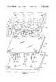
- FIG. 1is a front view of a blood analysis instrument in accordance with the invention
- FIG. 2is a sectional view, taken along the line 2--2, of the valve array employed in the instrument shown in FIG. 1;
- FIG. 3is an exploded view of components of the valve array shown in FIG. 2;
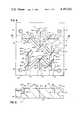
- FIG. 4is an elevational view of the face plate of the valve array showing details of the flow network
- FIG. 5is a sectional view taken along the line 5--5 of FIG. 4;
- FIG. 6is a perspective view of a valve actuator rod
- FIG. 7is a view of a valve in accordance with the invention in closed position
- FIG. 8is a sectional view taken along the line 8--8 of FIG. 7;
- FIG. 9is a view of the valve of FIG. 7 in open position
- FIG. 10is a sectional view taken along the line 10--10 of FIG. 9.
- FIGS. 11-16are diagrams showing operational sequences of the instrument shown in FIG. 1.
- FIG. 1Shown in FIG. 1 is a front view of a blood analysis instrument that includes a sample probe 10, a valve array 12, a potassium sensing electrode 14, a sodium sensing electrode 16, and a reference electrode 18.
- Sample probe 10is movable between a waste receptacle 20 and a sample source.
- Inlet line 22is connected between sample probe 10 and inlet 26 of the valve array.
- Rigid tube 28is connected between valve array outlet 30 and the potassium sensing electrode 14.
- Connected to reference electrode 18 through line 32 and pinch valve 34is a source 36 of reference electrolyte.
- Line 40 from reference electrode assembly 18is connected through peristaltic pump 42 to waste receptacle 20.
- Valve array 12also has an inlet 50 connected via line 52 to a first source 54 of calibrating fluid: an inlet 56 connected via line 58 to a second source 60 of calibrating fluid; a third inlet 62 connected via line 64 to a source 66 of conditioner for the sodium electrode 16; and ports 68, 70 connected to peristaltic pump 72.
- the valve array 12includes nine valves 80 and an array of interconnecting passages; passage 82 extending from port 26 to valve 80-1; passage 84 extending from valve 80-1 to valve 80-2; passage 86 extending from valve 80-2 to valve 80-5; passage 88 extending from valve 80-5 to valve 80-3; passage 90 extending from valve 80-3 to outlet port 30; passage 92 extending from port 68 to valve 80-4; passage 94 extending from valve 80-4 to valve 80-5; passage 96 extending from valve 80-4 to port 70; passage 100 extending from valve 80-4 to valve 80-7; passage 102 extending from valve 80-7 to valve 80-8; passage 104 extending from valve 80-8 to valve 80-9; passage 106 extending from valve 80-9 to valve 80-6; passage 108 extending from valve 80-7 to port 50; passage 110 extending from valve 80-8 to port 56; and passage 112 extending from valve 80-9 to port 62.
- FIG. 2A sectional view of the valve array 12 is shown in FIG. 2.
- That valve arrayincludes a transparent face plate 120 of cast acrylic resin that has a width of about eight centimeters, a length of about 81/2 centimeters, and a depth of about 11/2 centimeters. Clamped against the bottom surface of face plate 120 is a manifold diaphragm sheet 122 of white polyurethane of 40 shore A durometer hardness that has a smooth, pit-free surface 124 (the mold surface having a mirror polish) seated against the surface 126 of the raised land array 128 (FIG. 4) on the lower surface of plate 120.
- a manifold diaphragm sheet 122 of white polyurethane of 40 shore A durometer hardnessthat has a smooth, pit-free surface 124 (the mold surface having a mirror polish) seated against the surface 126 of the raised land array 128 (FIG. 4) on the lower surface of plate 120.
- Diaphragm sheet 122has a thickness of about three millimeters and its width and length dimensions are slightly less than the width and length dimensions of face plate 120.
- Apertured aluminum backing plate 130has a thickness of about six millimeters and the same width and length dimensions as face plate 120.
- Mounting plate 132is biased against the bottom of backing plate 130 by springs 134 which are supported on headed studs 136 that pass through holes 138 in solenoid support plate 140 and then through holes 141 in mounting plate 132, holes 144 in backing plate 130, holes 146 in diaphragm sheet 122 and are secured in threaded bores 148 in face plate 120.
- actuator 150Secured to diaphragm member 122 is an array of nine actuators 150, the head 152 of each being embedded in the polyurethane manifold sheet 122.
- Each actuator 150is connected by a threaded section 154 and coupling 156 to a solenoid actuator 158.
- a spring 160(of about one pound closing force) is seated between surface 162 of plunger 150 and recess 164 of mounting plate 132.
- Land array 128includes a set of nine generally circular valve sites 166, each about 11/4 centimeter in diameter, and interconnection lands 168, each about 5/8 centimeter in length.
- Surface 126 of the land array 128is about 0.4 millimeter above the base surface of face plate 120 and is flat and smooth (RMS 32).
- each valve land and interconnecting landFormed in each valve land and interconnecting land is one or more channels, in the form of grooves or trenches 170 (each about 0.8 millimeter in width and about 0.6 millimeter in depth formed by a ball end mill); through bores 172-1 and 172-2, each about 0.8 millimeter in diameter; and L-shaped passages 174, each of which extends between an external port and a groove in a valve land.
- passage 82extends from port 26 through L-shaped passage 174-1 and groove 170-1 to land 176-1 at valve site 166-1; and groove 170-2 extends from valve site 166-1 through valve sites 166-2 and 166-5 to land 176-3 at valve site 166-3.
- valve land 176At each valve site is a valve land 176 about 1/4 millimeter in width; land 176-1 separating channels 170-1 and 170-2; land 176-2 separating bore 172-1 from stub extension 178 of channel 170-2; land 176-3 separating the end of channel 170-2 from channel 170-3; land 176-5 separating channel 170-2 from channel 170-4; land 176-4 separating channels 170-4 and 170-5; land 176-6 separating channel 170-5 from bore 172-2; land 176-7 separating channel 170-5 from passage 174-5; land 176-8 separating channel 170-5 from 170-6; and land 176-9 separating channel 170-5 from passage 174-7.
- Each rodhas a head portion 152 about three millimeters in diameter and about four millimeters in length, a shaft section 180 about two millimeters in diameter with a threaded section 154 about six millimeters in length and a foot portion 184.
- Formed in head portion 152is an axially extending bore 186 about 13/4 millimeter in diameter and 21/2 millimeters deep; and two transverse bores 188, 190 that extend through head 152 and each is about one millimeter in diameter.
- the heads 152 of actuator 150are embedded in the manifold diaphragm 122 during the molding operation with polyurethane flowing through bores 186, 188, and 190 to securely affix the actuator head 152 to the diaphragm sheet 122.
- FIGS. 7 and 8Shown in FIGS. 7 and 8 is a view of a valve 80 in closed position with diaphragm surface 124 seated on land 176.
- the inlet channel 170Ais filled with blood (which is visible through transparent face plate 120) but flow to the outlet channel 170B is blocked by the firm seating of diaphragm surface 124 against land 176, in a "zero deadspace" valving action.
- Movement of actuator 150 by its solenoid 158an axial travel of about 3/4 millimeter moves the valve to its fully open position as shown in FIGS. 9 and 10.
- a valve chamber 192 of frustoconical configurationis formed over land 176 with a circular peripheral margin 194 in contact with plate surface 126, and a generally flat surface 196 spaced from land 176.
- the blood from channel 170Aflows through chamber 192 to outlet channel 170B, and the fluid color contrast with the white background of diaphragm 122 (a circular area about four millimeters in diameter) provides an indication that is clearly visible through the transparent face plate 120 of the open position of the valve.
- Isolation valves 80-1 and 80-3are of the type shown in FIGS. 7-10; T-valves 80-5, 80-7, 80-8, and 80-9 have a straight through channel that is always open and a second channel separated from the straight through channel by a valve land; vent valves 80-2 and 80-6 have a channel separated from a perpendicular vent passage via a valve land; and shunt valve 80-4 has two flow through channels separated by a valve land.
- FIGS. 11-16An operational sequence of the instrument is indicated in the diagrams of FIGS. 11-16.
- valves 80-1 and 80-3are opened by their respective solenoids 158-1 and 158-3, and peristaltic pump 42 is operated to inspirate sample 202 through probe 10 to sensor 24.
- sensor 24signals that the desired quantity of sample to be analyzed (about 180 microliter volume of blood or serum)
- valve 80-1is closed and valve 80-2 is opened to vent the line between valve 80-1 and pump 42.
- Pump 42is then stopped and the sample 202 to be analyzed thus is stored in line 22 as indicated in FIG. 11.
- vent valve 80-2When probe 10 has been wiped and inserted into waste receptacle 20, vent valve 80-2 is closed and probe isolation valve 80-1 is opened, and pump 42 is again energized to draw the sample 202 through the valve array 12 into the sample chambers of electrode systems 14 and 16.
- pump 42is again energized to draw the sample 202 through the valve array 12 into the sample chambers of electrode systems 14 and 16.
- valve 80-2As the blood sample 202 is being drawn past valve 80-2, that valve is pulsed seven times, the valve being open for about 40 milliseconds and closed for about 130 milliseconds at each pulse cycle, so that seven segments 204 of air are inserted into the leading portion of sample 202, as indicated in FIG. 12. This segmenting of the blood sample produces liquid flow transients which clean the surfaces of the flow passages and analysis chambers.
- Electrode isolation valve 80-3is closed on the trailing portion of the blood sample 202 as indicated in FIG. 13, so that the blood sample is held in the analysis chambers of potassium electrode 14 and sodium electrode 16.
- Pinch valve 34is simultaneously opened and electrolyte 206 is drawn from reservoir 36 past reference electrode 18 and through junction 38 to form a conductive path from reference electrode 18 to the blood sample 202 as indicated in FIG. 13.
- pump 42is stopped and the electrodes 14, 16 are allowed to equilibrate with the sample 202.
- probe 10is back flushed by means of pump 72.
- Valves 80-1, 80-5, and 80-6are opened. With valve 80-4 closed, pump 72 is operated and the manifold line (sections 100, 102, 104, and 106) is dried, the liquid being pumped by pump 72 from the manifold through probe 10 into waste receptacle 20.
- Calibrant valve 80-7is then opened and liquid 208 is drawn from reservoir 54 by pump 72 in a back flushing flow through sample probe 10 to waste container 20.
- pulse operation of valve 80-6introduces segments 210 of air into the leading portion of the flush liquid 208 as indicated in FIG. 14. After the back flush interval, all pumping is stopped for the remainder of the equilibration interval (about eight seconds), and then data is taken from the sodium and potassium electrode systems.
- Valves 80-1 and 80-3are opened and probe 10 is aspirated dry by pump 42 with concurrent pulsing of valve 80-2 to clean that valve.
- Valve 80-1is then closed; valves 80-4, 80-5, and 80-7 are opened; and pump 42 pulls calibrating liquid from reservoir 54 through the sample analysis chambers of electrode systems 14 and 16 as indicated in FIG. 15.
- This flow of liquidhas its leading edge segmented by operation of air valve 80-6 to provide cleaning action of the flow passage surfaces and analysis chambers; and then valve 80-6 is closed so that there is a continuous flow of calibration fluid through the analysis chambers of electrode systems 14 and 16 as indicated in FIG. 15.
- Valve 80-3is then closed and valve 34 is opened to create an electrolyte-calibration liquid interface at junctions 38, and the calibration of electrodes 14 and 16 is checked.
- each valve in the sample flow path(valves 80-1, 80-2, 80-5, and 80-3) is opened and closed in a flutter action which provides effective cleaning of the valve chambers 192.
- the valves, probe 10, and the analysis chambers of the electrode systems 14 and 16are cleaned in preparation for the next analysis cycle.
- Calibration fluid from reservoir 60 or conditioning fluid from reservoir 66may similarly be pumped through the analysis chambers of electrode systems 14 and 16.
- calibration liquid 212is pumped from the reservoir 60, the closed valve 80-7 providing complete isolation of calibration liquid 206.
- manifold vent valve 80-6is first opened together with valves 80-4, 80-5 and 80-7, and pump 42 clears (dries) the entire manifold line (sections 94, 100, 102, 104 and 106).
- Valve 80-6is then closed and valve 80-7 is opened so that liquid is pumped from reservoir 60 through the analysis chambers as indicated in FIG. 16. The flow of each such liquid may be segmented with air by operation of valve 80-6, as desired.
- the analysis systemprovides efficient handling of small volumes of specimens to be analyzed.
- a blood or serum specimen of less than 200 microliters volumeis analyzed while the volume of a urine specimen is about 700 microliters.
- Cross-contaminationis minimized by the valve configurations, the manifold arrangement and the valve interconnections.
- Each liquid linecan be pumped dry so that there is no liquid-liquid interface, and each has a valved vent to atmosphere.
- Each valveis easily cleaned and has low (essentially zero) residual volume.
Landscapes
- Chemical & Material Sciences (AREA)
- Health & Medical Sciences (AREA)
- Life Sciences & Earth Sciences (AREA)
- General Health & Medical Sciences (AREA)
- Analytical Chemistry (AREA)
- Biochemistry (AREA)
- Physics & Mathematics (AREA)
- General Physics & Mathematics (AREA)
- Immunology (AREA)
- Pathology (AREA)
- Molecular Biology (AREA)
- Chemical Kinetics & Catalysis (AREA)
- Electrochemistry (AREA)
- Automatic Analysis And Handling Materials Therefor (AREA)
Abstract
Description
Claims (28)
Priority Applications (1)
| Application Number | Priority Date | Filing Date | Title |
|---|---|---|---|
| US06/165,051US4283262A (en) | 1980-07-01 | 1980-07-01 | Analysis system |
Applications Claiming Priority (1)
| Application Number | Priority Date | Filing Date | Title |
|---|---|---|---|
| US06/165,051US4283262A (en) | 1980-07-01 | 1980-07-01 | Analysis system |
Publications (1)
| Publication Number | Publication Date |
|---|---|
| US4283262Atrue US4283262A (en) | 1981-08-11 |
Family
ID=22597218
Family Applications (1)
| Application Number | Title | Priority Date | Filing Date |
|---|---|---|---|
| US06/165,051Expired - LifetimeUS4283262A (en) | 1980-07-01 | 1980-07-01 | Analysis system |
Country Status (1)
| Country | Link |
|---|---|
| US (1) | US4283262A (en) |
Cited By (63)
| Publication number | Priority date | Publication date | Assignee | Title |
|---|---|---|---|---|
| US4410631A (en)* | 1980-07-21 | 1983-10-18 | Instrumentation Laboratory Inc. | Compensated reference liquid |
| US4512953A (en)* | 1981-05-25 | 1985-04-23 | Avl Ag | Analyzing apparatus for the analysis of liquid samples |
| US4531088A (en)* | 1982-08-06 | 1985-07-23 | Allied Corporation | Blood analysis |
| WO1985004719A1 (en)* | 1984-04-11 | 1985-10-24 | Sentech Medical Corporation | Self-calibrating single-use sensing device for clinical chemistry analyzer |
| EP0107631A3 (en)* | 1982-09-28 | 1986-02-19 | Bifok Ab | Integrated microconduits for continuous flow analysis |
| JPS61155838A (en)* | 1984-12-21 | 1986-07-15 | イエル・ホールディング・エス・ピー・ア | particle analysis system |
| US4627893A (en)* | 1984-03-28 | 1986-12-09 | Amdev, Inc. | Means and methods for quantitative determination of analyte in liquids |
| US4640821A (en)* | 1985-07-16 | 1987-02-03 | Fisher Scientific Company | Analysis apparatus |
| US4649028A (en)* | 1985-03-27 | 1987-03-10 | Medica Corporation | Electrolyte analyzer |
| US4654127A (en)* | 1984-04-11 | 1987-03-31 | Sentech Medical Corporation | Self-calibrating single-use sensing device for clinical chemistry and method of use |
| EP0193939A3 (en)* | 1985-03-07 | 1987-07-15 | Max-Planck-Gesellschaft zur Förderung der Wissenschaften e.V. | Line system for laboratory purposes |
| EP0241611A1 (en)* | 1984-02-22 | 1987-10-21 | Allelix Inc. | Device for performing chemical or immunochemical assays |
| EP0180063A3 (en)* | 1984-11-01 | 1987-12-02 | Fisher Scientific Company | Liquid handling process |
| EP0180064A3 (en)* | 1984-11-01 | 1987-12-09 | Fisher Scientific Company | Liquid handling system |
| EP0189316A3 (en)* | 1985-01-25 | 1988-05-04 | Analytix, Inc. | Measurement or detection of chemical entities |
| US4786372A (en)* | 1985-07-22 | 1988-11-22 | Amdev, Inc. | Electrochemical measuring |
| EP0257797A3 (en)* | 1986-08-27 | 1988-11-30 | Vincent Robert Farnsworth | Valve block assemblies |
| US4797191A (en)* | 1984-05-08 | 1989-01-10 | Fresenius Ag | Measuring device for determination of the activity or of the concentration of ions in solutions |
| EP0242644A3 (en)* | 1986-04-05 | 1989-04-05 | Kuraray Co., Ltd. | Blood component monitoring system |
| US4844872A (en)* | 1987-07-17 | 1989-07-04 | Fisher Scientific Company | Fluid handling |
| US4865811A (en)* | 1986-07-01 | 1989-09-12 | Biotec Instruments Limited | Apparatus for automatic chemical analysis |
| US5019238A (en)* | 1984-03-28 | 1991-05-28 | Baxter Diagnostics Inc. | Means for quantitative determination of analyte in liquids |
| EP0436995A3 (en)* | 1990-01-08 | 1991-12-04 | Eastman Kodak Company | Transfer apparatus for chemical reaction pack |
| US5088515A (en)* | 1989-05-01 | 1992-02-18 | Kamen Dean L | Valve system with removable fluid interface |
| US5506142A (en)* | 1991-12-13 | 1996-04-09 | Dade International Inc. | Probe wash for liquid analysis apparatus |
| US5571396A (en)* | 1993-07-12 | 1996-11-05 | Dade International Inc. | Fluid analysis system and sensing electrode, electrode assembly, and sensing module components |
| WO1997041429A1 (en)* | 1996-04-26 | 1997-11-06 | Biosepra, Inc. | FLOW THROUGH FLUID pH AND CONDUCTIVITY SENSOR |
| US5846396A (en)* | 1994-11-10 | 1998-12-08 | Sarnoff Corporation | Liquid distribution system |
| US5980704A (en)* | 1995-06-07 | 1999-11-09 | David Sarnoff Research Center Inc. | Method and system for inhibiting cross-contamination in fluids of combinatorial chemistry device |
| US6033544A (en)* | 1996-10-11 | 2000-03-07 | Sarnoff Corporation | Liquid distribution system |
| US6117396A (en)* | 1998-02-18 | 2000-09-12 | Orchid Biocomputer, Inc. | Device for delivering defined volumes |
| US6485690B1 (en) | 1999-05-27 | 2002-11-26 | Orchid Biosciences, Inc. | Multiple fluid sample processor and system |
| US20030019749A1 (en)* | 2001-07-24 | 2003-01-30 | Mettler-Toledo Gmbh | Apparatus and method for treating a measuring probe |
| US20040007463A1 (en)* | 1999-08-12 | 2004-01-15 | Ramsey J. Michael | Microfluidic devices for the controlled manipulation of small volumes |
| US20050220668A1 (en)* | 2004-04-06 | 2005-10-06 | Bio/Data Corporation | Disposable test device with sample volume measurement and mixing methods |
| US20070089543A1 (en)* | 2005-09-27 | 2007-04-26 | Narihiro Oku | Sample analyzer |
| RU2340888C2 (en)* | 2004-08-27 | 2008-12-10 | Борис Романович Пырсиков | Potentiometric measurements device |
| US20110217712A1 (en)* | 2010-03-02 | 2011-09-08 | Quantalife, Inc. | Emulsion chemistry for encapsulated droplets |
| USRE43365E1 (en) | 2003-03-14 | 2012-05-08 | Lawrence Livermore National Security, Llc | Apparatus for chemical amplification based on fluid partitioning in an immiscible liquid |
| US8633015B2 (en) | 2008-09-23 | 2014-01-21 | Bio-Rad Laboratories, Inc. | Flow-based thermocycling system with thermoelectric cooler |
| US8663920B2 (en) | 2011-07-29 | 2014-03-04 | Bio-Rad Laboratories, Inc. | Library characterization by digital assay |
| US8709762B2 (en) | 2010-03-02 | 2014-04-29 | Bio-Rad Laboratories, Inc. | System for hot-start amplification via a multiple emulsion |
| US8730479B2 (en) | 2010-03-25 | 2014-05-20 | Bio-Rad Laboratories, Inc. | Detection system for droplet-based assays |
| US8951939B2 (en) | 2011-07-12 | 2015-02-10 | Bio-Rad Laboratories, Inc. | Digital assays with multiplexed detection of two or more targets in the same optical channel |
| US9089844B2 (en) | 2010-11-01 | 2015-07-28 | Bio-Rad Laboratories, Inc. | System for forming emulsions |
| US9126160B2 (en) | 2008-09-23 | 2015-09-08 | Bio-Rad Laboratories, Inc. | System for forming an array of emulsions |
| US9132394B2 (en) | 2008-09-23 | 2015-09-15 | Bio-Rad Laboratories, Inc. | System for detection of spaced droplets |
| US9194861B2 (en) | 2009-09-02 | 2015-11-24 | Bio-Rad Laboratories, Inc. | Method of mixing fluids by coalescence of multiple emulsions |
| US9222128B2 (en) | 2011-03-18 | 2015-12-29 | Bio-Rad Laboratories, Inc. | Multiplexed digital assays with combinatorial use of signals |
| US9347059B2 (en) | 2011-04-25 | 2016-05-24 | Bio-Rad Laboratories, Inc. | Methods and compositions for nucleic acid analysis |
| US9393560B2 (en) | 2010-03-25 | 2016-07-19 | Bio-Rad Laboratories, Inc. | Droplet transport system for detection |
| US9399215B2 (en) | 2012-04-13 | 2016-07-26 | Bio-Rad Laboratories, Inc. | Sample holder with a well having a wicking promoter |
| US9417190B2 (en) | 2008-09-23 | 2016-08-16 | Bio-Rad Laboratories, Inc. | Calibrations and controls for droplet-based assays |
| US9492797B2 (en) | 2008-09-23 | 2016-11-15 | Bio-Rad Laboratories, Inc. | System for detection of spaced droplets |
| US9500664B2 (en) | 2010-03-25 | 2016-11-22 | Bio-Rad Laboratories, Inc. | Droplet generation for droplet-based assays |
| US9764322B2 (en) | 2008-09-23 | 2017-09-19 | Bio-Rad Laboratories, Inc. | System for generating droplets with pressure monitoring |
| US10512910B2 (en) | 2008-09-23 | 2019-12-24 | Bio-Rad Laboratories, Inc. | Droplet-based analysis method |
| US20210123936A1 (en)* | 2018-07-10 | 2021-04-29 | Precision Planting Llc | Agricultural sampling system and related methods |
| US11130128B2 (en) | 2008-09-23 | 2021-09-28 | Bio-Rad Laboratories, Inc. | Detection method for a target nucleic acid |
| US12090480B2 (en) | 2008-09-23 | 2024-09-17 | Bio-Rad Laboratories, Inc. | Partition-based method of analysis |
| US12097495B2 (en) | 2011-02-18 | 2024-09-24 | Bio-Rad Laboratories, Inc. | Methods and compositions for detecting genetic material |
| US12162008B2 (en) | 2008-09-23 | 2024-12-10 | Bio-Rad Laboratories, Inc. | Partition-based method of analysis |
| US12168231B2 (en) | 2008-09-23 | 2024-12-17 | Bio-Rad Laboratories, Inc. | Method of analysis |
Citations (6)
| Publication number | Priority date | Publication date | Assignee | Title |
|---|---|---|---|---|
| US3098718A (en)* | 1959-09-08 | 1963-07-23 | Technicon Instr | Concentration apparatus for quantitative analysis of a substance in a liquid |
| US3165693A (en)* | 1961-05-15 | 1965-01-12 | Technicon Instr | Continuously operable apparatus and method for counting particles in successive portions of a flowing fluid stream |
| US3211645A (en)* | 1962-07-17 | 1965-10-12 | Technicon Instr | Method and apparatus for filtering sanguineous liquid streams |
| US3241923A (en)* | 1959-10-30 | 1966-03-22 | Technicon Instr | Method and apparatus for the treatment of liquids |
| US4108602A (en)* | 1976-10-20 | 1978-08-22 | Hanson Research Corporation | Sample changing chemical analysis method and apparatus |
| US4219530A (en)* | 1978-01-27 | 1980-08-26 | Brinkmann Instruments, Inc. | Apparatus for analyzing biological specimens |
- 1980
- 1980-07-01USUS06/165,051patent/US4283262A/ennot_activeExpired - Lifetime
Patent Citations (6)
| Publication number | Priority date | Publication date | Assignee | Title |
|---|---|---|---|---|
| US3098718A (en)* | 1959-09-08 | 1963-07-23 | Technicon Instr | Concentration apparatus for quantitative analysis of a substance in a liquid |
| US3241923A (en)* | 1959-10-30 | 1966-03-22 | Technicon Instr | Method and apparatus for the treatment of liquids |
| US3165693A (en)* | 1961-05-15 | 1965-01-12 | Technicon Instr | Continuously operable apparatus and method for counting particles in successive portions of a flowing fluid stream |
| US3211645A (en)* | 1962-07-17 | 1965-10-12 | Technicon Instr | Method and apparatus for filtering sanguineous liquid streams |
| US4108602A (en)* | 1976-10-20 | 1978-08-22 | Hanson Research Corporation | Sample changing chemical analysis method and apparatus |
| US4219530A (en)* | 1978-01-27 | 1980-08-26 | Brinkmann Instruments, Inc. | Apparatus for analyzing biological specimens |
Cited By (105)
| Publication number | Priority date | Publication date | Assignee | Title |
|---|---|---|---|---|
| US4410631A (en)* | 1980-07-21 | 1983-10-18 | Instrumentation Laboratory Inc. | Compensated reference liquid |
| US4512953A (en)* | 1981-05-25 | 1985-04-23 | Avl Ag | Analyzing apparatus for the analysis of liquid samples |
| US4531088A (en)* | 1982-08-06 | 1985-07-23 | Allied Corporation | Blood analysis |
| EP0107631A3 (en)* | 1982-09-28 | 1986-02-19 | Bifok Ab | Integrated microconduits for continuous flow analysis |
| EP0241611A1 (en)* | 1984-02-22 | 1987-10-21 | Allelix Inc. | Device for performing chemical or immunochemical assays |
| US4627893A (en)* | 1984-03-28 | 1986-12-09 | Amdev, Inc. | Means and methods for quantitative determination of analyte in liquids |
| US5019238A (en)* | 1984-03-28 | 1991-05-28 | Baxter Diagnostics Inc. | Means for quantitative determination of analyte in liquids |
| WO1985004719A1 (en)* | 1984-04-11 | 1985-10-24 | Sentech Medical Corporation | Self-calibrating single-use sensing device for clinical chemistry analyzer |
| US4654127A (en)* | 1984-04-11 | 1987-03-31 | Sentech Medical Corporation | Self-calibrating single-use sensing device for clinical chemistry and method of use |
| US4797191A (en)* | 1984-05-08 | 1989-01-10 | Fresenius Ag | Measuring device for determination of the activity or of the concentration of ions in solutions |
| EP0180063A3 (en)* | 1984-11-01 | 1987-12-02 | Fisher Scientific Company | Liquid handling process |
| EP0180064A3 (en)* | 1984-11-01 | 1987-12-09 | Fisher Scientific Company | Liquid handling system |
| EP0420296A1 (en)* | 1984-11-01 | 1991-04-03 | INSTRUMENTATION LABORATORY S.p.A. | Liquid handling system |
| JPS61155838A (en)* | 1984-12-21 | 1986-07-15 | イエル・ホールディング・エス・ピー・ア | particle analysis system |
| US4607526A (en)* | 1984-12-21 | 1986-08-26 | Allied Corporation | Particle analysis system |
| EP0189316A3 (en)* | 1985-01-25 | 1988-05-04 | Analytix, Inc. | Measurement or detection of chemical entities |
| EP0193939A3 (en)* | 1985-03-07 | 1987-07-15 | Max-Planck-Gesellschaft zur Förderung der Wissenschaften e.V. | Line system for laboratory purposes |
| US4649028A (en)* | 1985-03-27 | 1987-03-10 | Medica Corporation | Electrolyte analyzer |
| US4640821A (en)* | 1985-07-16 | 1987-02-03 | Fisher Scientific Company | Analysis apparatus |
| US4786372A (en)* | 1985-07-22 | 1988-11-22 | Amdev, Inc. | Electrochemical measuring |
| EP0242644A3 (en)* | 1986-04-05 | 1989-04-05 | Kuraray Co., Ltd. | Blood component monitoring system |
| US4865811A (en)* | 1986-07-01 | 1989-09-12 | Biotec Instruments Limited | Apparatus for automatic chemical analysis |
| EP0257797A3 (en)* | 1986-08-27 | 1988-11-30 | Vincent Robert Farnsworth | Valve block assemblies |
| US4844872A (en)* | 1987-07-17 | 1989-07-04 | Fisher Scientific Company | Fluid handling |
| US5088515A (en)* | 1989-05-01 | 1992-02-18 | Kamen Dean L | Valve system with removable fluid interface |
| EP0436995A3 (en)* | 1990-01-08 | 1991-12-04 | Eastman Kodak Company | Transfer apparatus for chemical reaction pack |
| US5506142A (en)* | 1991-12-13 | 1996-04-09 | Dade International Inc. | Probe wash for liquid analysis apparatus |
| US5571396A (en)* | 1993-07-12 | 1996-11-05 | Dade International Inc. | Fluid analysis system and sensing electrode, electrode assembly, and sensing module components |
| US5846396A (en)* | 1994-11-10 | 1998-12-08 | Sarnoff Corporation | Liquid distribution system |
| US5980704A (en)* | 1995-06-07 | 1999-11-09 | David Sarnoff Research Center Inc. | Method and system for inhibiting cross-contamination in fluids of combinatorial chemistry device |
| US6331439B1 (en) | 1995-06-07 | 2001-12-18 | Orchid Biosciences, Inc. | Device for selective distribution of liquids |
| WO1997041429A1 (en)* | 1996-04-26 | 1997-11-06 | Biosepra, Inc. | FLOW THROUGH FLUID pH AND CONDUCTIVITY SENSOR |
| US5945830A (en)* | 1996-04-26 | 1999-08-31 | Biosepra, Inc. | Flow through fluid pH and conductivity sensor |
| US6033544A (en)* | 1996-10-11 | 2000-03-07 | Sarnoff Corporation | Liquid distribution system |
| US6117396A (en)* | 1998-02-18 | 2000-09-12 | Orchid Biocomputer, Inc. | Device for delivering defined volumes |
| US6485690B1 (en) | 1999-05-27 | 2002-11-26 | Orchid Biosciences, Inc. | Multiple fluid sample processor and system |
| US20040007463A1 (en)* | 1999-08-12 | 2004-01-15 | Ramsey J. Michael | Microfluidic devices for the controlled manipulation of small volumes |
| US7238268B2 (en)* | 1999-08-12 | 2007-07-03 | Ut-Battelle, Llc | Microfluidic devices for the controlled manipulation of small volumes |
| US20070227890A1 (en)* | 1999-08-12 | 2007-10-04 | Ramsey J M | Microfluidic devices for the controlled manipulation of small volumes |
| US8268633B2 (en)* | 1999-08-12 | 2012-09-18 | Ut-Battelle, Llc | Microfluidic devices for the controlled manipulation of small volumes |
| EP1279951A3 (en)* | 2001-07-24 | 2005-06-08 | Mettler-Toledo GmbH | Apparatus for the treatment of a measurement probe and their applications |
| US20030019749A1 (en)* | 2001-07-24 | 2003-01-30 | Mettler-Toledo Gmbh | Apparatus and method for treating a measuring probe |
| USRE47080E1 (en) | 2003-03-14 | 2018-10-09 | Lawrence Livermore National Security, Llc | Chemical amplification based on fluid partitioning |
| USRE48788E1 (en) | 2003-03-14 | 2021-10-26 | Lawrence Livermore National Security, Llc | Chemical amplification based on fluid partitioning |
| USRE45539E1 (en) | 2003-03-14 | 2015-06-02 | Lawrence Livermore National Security, Llc | Method for chemical amplification based on fluid partitioning in an immiscible liquid |
| USRE43365E1 (en) | 2003-03-14 | 2012-05-08 | Lawrence Livermore National Security, Llc | Apparatus for chemical amplification based on fluid partitioning in an immiscible liquid |
| USRE46322E1 (en) | 2003-03-14 | 2017-02-28 | Lawrence Livermore National Security, Llc | Method for chemical amplification based on fluid partitioning in an immiscible liquid |
| US20050220668A1 (en)* | 2004-04-06 | 2005-10-06 | Bio/Data Corporation | Disposable test device with sample volume measurement and mixing methods |
| RU2340888C2 (en)* | 2004-08-27 | 2008-12-10 | Борис Романович Пырсиков | Potentiometric measurements device |
| US20070089543A1 (en)* | 2005-09-27 | 2007-04-26 | Narihiro Oku | Sample analyzer |
| US9132394B2 (en) | 2008-09-23 | 2015-09-15 | Bio-Rad Laboratories, Inc. | System for detection of spaced droplets |
| US9248417B2 (en) | 2008-09-23 | 2016-02-02 | Bio-Rad Laboratories, Inc. | System for droplet-based assays using an array of emulsions |
| US11633739B2 (en) | 2008-09-23 | 2023-04-25 | Bio-Rad Laboratories, Inc. | Droplet-based assay system |
| US12090480B2 (en) | 2008-09-23 | 2024-09-17 | Bio-Rad Laboratories, Inc. | Partition-based method of analysis |
| US9126160B2 (en) | 2008-09-23 | 2015-09-08 | Bio-Rad Laboratories, Inc. | System for forming an array of emulsions |
| US12162008B2 (en) | 2008-09-23 | 2024-12-10 | Bio-Rad Laboratories, Inc. | Partition-based method of analysis |
| US9156010B2 (en) | 2008-09-23 | 2015-10-13 | Bio-Rad Laboratories, Inc. | Droplet-based assay system |
| US11130134B2 (en) | 2008-09-23 | 2021-09-28 | Bio-Rad Laboratories, Inc. | Method of performing droplet-based assays |
| US9216392B2 (en) | 2008-09-23 | 2015-12-22 | Bio-Rad Laboratories, Inc. | System for forming an array of emulsions |
| US11130128B2 (en) | 2008-09-23 | 2021-09-28 | Bio-Rad Laboratories, Inc. | Detection method for a target nucleic acid |
| US9243288B2 (en) | 2008-09-23 | 2016-01-26 | Bio-Rad Laboratories, Inc. | Cartridge with lysis chamber and droplet generator |
| US11612892B2 (en) | 2008-09-23 | 2023-03-28 | Bio-Rad Laboratories, Inc. | Method of performing droplet-based assays |
| US10512910B2 (en) | 2008-09-23 | 2019-12-24 | Bio-Rad Laboratories, Inc. | Droplet-based analysis method |
| US10279350B2 (en) | 2008-09-23 | 2019-05-07 | Bio-Rad Laboratories, Inc. | Method of generating droplets |
| US10258989B2 (en) | 2008-09-23 | 2019-04-16 | Bio-Rad Laboratories, Inc. | Method of making a device for generating droplets |
| US9417190B2 (en) | 2008-09-23 | 2016-08-16 | Bio-Rad Laboratories, Inc. | Calibrations and controls for droplet-based assays |
| US9492797B2 (en) | 2008-09-23 | 2016-11-15 | Bio-Rad Laboratories, Inc. | System for detection of spaced droplets |
| US10258988B2 (en) | 2008-09-23 | 2019-04-16 | Bio-Rad Laboratories, Inc. | Device for generating droplets |
| US8633015B2 (en) | 2008-09-23 | 2014-01-21 | Bio-Rad Laboratories, Inc. | Flow-based thermocycling system with thermoelectric cooler |
| US12168231B2 (en) | 2008-09-23 | 2024-12-17 | Bio-Rad Laboratories, Inc. | Method of analysis |
| US9623384B2 (en) | 2008-09-23 | 2017-04-18 | Bio-Rad Laboratories, Inc. | System for transporting emulsions from an array to a detector |
| US9636682B2 (en) | 2008-09-23 | 2017-05-02 | Bio-Rad Laboratories, Inc. | System for generating droplets—instruments and cassette |
| US9649635B2 (en) | 2008-09-23 | 2017-05-16 | Bio-Rad Laboratories, Inc. | System for generating droplets with push-back to remove oil |
| US9764322B2 (en) | 2008-09-23 | 2017-09-19 | Bio-Rad Laboratories, Inc. | System for generating droplets with pressure monitoring |
| US10166522B2 (en) | 2009-09-02 | 2019-01-01 | Bio-Rad Laboratories, Inc. | System for mixing fluids by coalescence of multiple emulsions |
| US9194861B2 (en) | 2009-09-02 | 2015-11-24 | Bio-Rad Laboratories, Inc. | Method of mixing fluids by coalescence of multiple emulsions |
| US10677693B2 (en) | 2009-09-02 | 2020-06-09 | Bio-Rad Laboratories, Inc. | System for mixing fluids by coalescence of multiple emulsions |
| US10378048B2 (en) | 2010-03-02 | 2019-08-13 | Bio-Rad Laboratories, Inc. | Emulsion chemistry for encapsulated droplets |
| US20110217712A1 (en)* | 2010-03-02 | 2011-09-08 | Quantalife, Inc. | Emulsion chemistry for encapsulated droplets |
| US9598725B2 (en) | 2010-03-02 | 2017-03-21 | Bio-Rad Laboratories, Inc. | Emulsion chemistry for encapsulated droplets |
| US8709762B2 (en) | 2010-03-02 | 2014-04-29 | Bio-Rad Laboratories, Inc. | System for hot-start amplification via a multiple emulsion |
| US11866771B2 (en) | 2010-03-02 | 2024-01-09 | Bio-Rad Laboratories, Inc. | Emulsion chemistry for encapsulated droplets |
| US11060136B2 (en) | 2010-03-02 | 2021-07-13 | Bio-Rad Laboratories, Inc. | Emulsion chemistry for encapsulated droplets |
| US9393560B2 (en) | 2010-03-25 | 2016-07-19 | Bio-Rad Laboratories, Inc. | Droplet transport system for detection |
| US8730479B2 (en) | 2010-03-25 | 2014-05-20 | Bio-Rad Laboratories, Inc. | Detection system for droplet-based assays |
| US10099219B2 (en) | 2010-03-25 | 2018-10-16 | Bio-Rad Laboratories, Inc. | Device for generating droplets |
| US10744506B2 (en) | 2010-03-25 | 2020-08-18 | Bio-Rad Laboratories, Inc. | Device for generating droplets |
| US12103005B2 (en) | 2010-03-25 | 2024-10-01 | Bio-Rad Laboratories, Inc. | Method of emulsion formation and modification |
| US9500664B2 (en) | 2010-03-25 | 2016-11-22 | Bio-Rad Laboratories, Inc. | Droplet generation for droplet-based assays |
| US10272432B2 (en) | 2010-03-25 | 2019-04-30 | Bio-Rad Laboratories, Inc. | Device for generating droplets |
| US9089844B2 (en) | 2010-11-01 | 2015-07-28 | Bio-Rad Laboratories, Inc. | System for forming emulsions |
| US12097495B2 (en) | 2011-02-18 | 2024-09-24 | Bio-Rad Laboratories, Inc. | Methods and compositions for detecting genetic material |
| US9222128B2 (en) | 2011-03-18 | 2015-12-29 | Bio-Rad Laboratories, Inc. | Multiplexed digital assays with combinatorial use of signals |
| US10190115B2 (en) | 2011-04-25 | 2019-01-29 | Bio-Rad Laboratories, Inc. | Methods and compositions for nucleic acid analysis |
| US9347059B2 (en) | 2011-04-25 | 2016-05-24 | Bio-Rad Laboratories, Inc. | Methods and compositions for nucleic acid analysis |
| US11939573B2 (en) | 2011-04-25 | 2024-03-26 | Bio-Rad Laboratories, Inc. | Methods and compositions for nucleic acid analysis |
| US10760073B2 (en) | 2011-04-25 | 2020-09-01 | Bio-Rad Laboratories, Inc. | Methods and compositions for nucleic acid analysis |
| US9885034B2 (en) | 2011-04-25 | 2018-02-06 | Bio-Rad Laboratories, Inc. | Methods and compositions for nucleic acid analysis |
| US8951939B2 (en) | 2011-07-12 | 2015-02-10 | Bio-Rad Laboratories, Inc. | Digital assays with multiplexed detection of two or more targets in the same optical channel |
| US8663920B2 (en) | 2011-07-29 | 2014-03-04 | Bio-Rad Laboratories, Inc. | Library characterization by digital assay |
| US9399215B2 (en) | 2012-04-13 | 2016-07-26 | Bio-Rad Laboratories, Inc. | Sample holder with a well having a wicking promoter |
| US20210123936A1 (en)* | 2018-07-10 | 2021-04-29 | Precision Planting Llc | Agricultural sampling system and related methods |
| US12000853B2 (en)* | 2018-07-10 | 2024-06-04 | Precision Planting Llc | Agricultural sampling, sample preparation and analysis system and related methods |
| US12055557B2 (en) | 2018-07-10 | 2024-08-06 | Precision Planting Llc | Agricultural sampling system and related methods |
| CN118706574A (en)* | 2018-07-10 | 2024-09-27 | 精密种植有限责任公司 | Agricultural sampling systems and related methods |
Similar Documents
| Publication | Publication Date | Title |
|---|---|---|
| US4283262A (en) | Analysis system | |
| US4304257A (en) | Valve with flexible sheet member | |
| US4640821A (en) | Analysis apparatus | |
| Shoji et al. | Prototype miniature blood gas analyser fabricated on a silicon wafer | |
| US4627893A (en) | Means and methods for quantitative determination of analyte in liquids | |
| US4607526A (en) | Particle analysis system | |
| US5599688A (en) | Device and method for circulating fluid over a membrane | |
| EP2381116A1 (en) | Apparatus and methods for conducting assays and high throughput screening | |
| US9354152B2 (en) | Rheometry apparatus | |
| US4844097A (en) | Apparatus and method for testing liquids | |
| GB2076969A (en) | Through flow electrochemical analysis system | |
| CN101773861B (en) | Microfluidic sample feeding method, device and application thereof | |
| US4361540A (en) | Analysis system | |
| JPS59206757A (en) | Device for electrochemically analyzing electrolytic component in sample liquid | |
| Glawdel et al. | Microfluidic system with integrated electroosmotic pumps, concentration gradient generator and fish cell line (RTgill-W1)—towards water toxicity testing | |
| JP4256270B2 (en) | Liquid feeding device and driving method thereof | |
| WO1995017658A1 (en) | Mechanical capture of count wafer for particle analysis | |
| US3926765A (en) | Electrochemical electrode structure | |
| US12434239B2 (en) | Microfluidic sample preparation device offering high repeatability | |
| EP0101236A2 (en) | A potentiometric analysis system and method of using such system to analyse blood | |
| JP2955705B2 (en) | Fluid measurement device | |
| CN106622408A (en) | Micro-fluidic chip based on MHD control | |
| EP1460415A1 (en) | Measurement device for measuring electric signal emitted by biological sample | |
| CN117491430A (en) | Detection assembly and blood gas analysis system | |
| CN217688681U (en) | Sample analyzer |
Legal Events
| Date | Code | Title | Description |
|---|---|---|---|
| STCF | Information on status: patent grant | Free format text:PATENTED CASE | |
| AS | Assignment | Owner name:ALLIED CORPORATION COLUMBIA ROAD AND PARK AVE., MO Free format text:ASSIGNMENT OF ASSIGNORS INTEREST.;ASSIGNOR:INSTRUMENTATION LABORATORY INC., A DE CORP;REEL/FRAME:004211/0801 Effective date:19840103 | |
| AS | Assignment | Owner name:FISHER SCIENTIFIC COMPANY A CORP OF DE Free format text:ASSIGNMENT OF ASSIGNORS INTEREST.;ASSIGNOR:ALLIED CORPORATION A NY CORP;REEL/FRAME:004634/0501 Effective date:19860815 | |
| AS | Assignment | Owner name:INIZIATIVE MARITTIME 1991, S.R.L., A CORPORATION Free format text:ASSIGNMENT OF ASSIGNORS INTEREST.;ASSIGNOR:FISHER SCIENTIFIC COMPANY, A CORP. OF DE;REEL/FRAME:005891/0407 Effective date:19911023 | |
| AS | Assignment | Owner name:CITIBANK N.A. Free format text:SECURITY INTEREST;ASSIGNOR:INIZIATIVE MARITTIME 1991, S.R.L.;REEL/FRAME:005913/0325 Effective date:19911023 | |
| AS | Assignment | Owner name:"IL HOLDING S.P.A." Free format text:CHANGE OF NAME;ASSIGNOR:INIZIATIVE MARITTIME 1991 S.R.L.;REEL/FRAME:006179/0983 Effective date:19920219 |