US4283175A - Dental scaler having scaling tip with rounded edge work surfaces particularly suitable for circular or ellipsoidal patterns of vibration - Google Patents
Dental scaler having scaling tip with rounded edge work surfaces particularly suitable for circular or ellipsoidal patterns of vibrationDownload PDFInfo
- Publication number
- US4283175A US4283175AUS06/091,018US9101879AUS4283175AUS 4283175 AUS4283175 AUS 4283175AUS 9101879 AUS9101879 AUS 9101879AUS 4283175 AUS4283175 AUS 4283175A
- Authority
- US
- United States
- Prior art keywords
- scaler
- plane
- tip
- free end
- inch
- Prior art date
- Legal status (The legal status is an assumption and is not a legal conclusion. Google has not performed a legal analysis and makes no representation as to the accuracy of the status listed.)
- Expired - Lifetime
Links
Images


Classifications
- A—HUMAN NECESSITIES
- A61—MEDICAL OR VETERINARY SCIENCE; HYGIENE
- A61C—DENTISTRY; APPARATUS OR METHODS FOR ORAL OR DENTAL HYGIENE
- A61C3/00—Dental tools or instruments
- A61C3/02—Tooth drilling or cutting instruments; Instruments acting like a sandblast machine
- A61C3/03—Instruments operated by vibration
- A—HUMAN NECESSITIES
- A61—MEDICAL OR VETERINARY SCIENCE; HYGIENE
- A61C—DENTISTRY; APPARATUS OR METHODS FOR ORAL OR DENTAL HYGIENE
- A61C17/00—Devices for cleaning, polishing, rinsing or drying teeth, teeth cavities or prostheses; Saliva removers; Dental appliances for receiving spittle
- A61C17/16—Power-driven cleaning or polishing devices
- A61C17/20—Power-driven cleaning or polishing devices using ultrasonics
- A—HUMAN NECESSITIES
- A61—MEDICAL OR VETERINARY SCIENCE; HYGIENE
- A61C—DENTISTRY; APPARATUS OR METHODS FOR ORAL OR DENTAL HYGIENE
- A61C17/00—Devices for cleaning, polishing, rinsing or drying teeth, teeth cavities or prostheses; Saliva removers; Dental appliances for receiving spittle
- A61C17/16—Power-driven cleaning or polishing devices
- A61C17/18—Chiselling scalers
Definitions
- Power driven dental scalersare well known. Of particular interest herein is a dental scaler having a scaling tip with an improved work surface configuration.
- Typical of the earlier air-driven dental scalersare those of U.S. Pat. No. 3,820,529 and U.S. Pat. No. 3,444,622 to Mills et al, which scalers utilize an air-driven ball contained in a chamber. Movement of the ball against the walls of the chamber imparts vibration to the chamber which vibrations are then transmitted to the scraping tool.
- a more recent type of air-driven scalerdescribed in U.S. Pat. No. 3,526,962 to Fuerst, utilizes a rotatable mandrel which has an irregularly-shaped tip engaged with a reciprocable block in which the mandrel tip is received.
- the Sertich-type dental scalerachieves these advantages in part by including a single, rigid vibratable tube mounted on resilient support washers disposed at or near the theoretical vibratory nodes characteristic of the natural vibrational mode of the tube.
- a work toolsuch as a scraper or a pick, is typically secured to the working end of the vibratable tube by a connection between an externally-threaded work tool shank and an internally threaded portion of the tube.
- the mode or pattern of vibration of the vibratable tube of the Sertich-type scaleris characteristically one which during one oscillation or cycle of vibration traces a path that may vary from circular to oval or ellipsoidal in shape. It has been found that this particular vibratory orbit provides maximum efficiency of energy transfer from the tube vibrating mechanism to the working tip.
- a rigid dental scaler tiphaving an operative end and an end adapted to be secured to a hand-held dental scaler, the operative end terminating in a curved free end, the operative end having a plurality of sides extending over a portion of the working end, a perpendicular cross-section of the operative end at any point along the working dimension thereof being a multi-sided figure, the curved free end lying in a plane passing through the longitudinal dimension of the scaler tip.
- the curved free endcan have a terminal portion lying outside of the plane in which the major portion of the curved free end lies.
- the scaler tip of the inventionis particularly suitable for use as a work tool connected to an air driven dental scaler comprising elongated casing means having a proximal end and a distal end, resilient support means within the casing means, a substantially rigid shaft within the elongated casing means, the shaft supported within the casing means by the resilient support means, and means for imparting vibration to the resiliently supported shaft to provide vibratory movement to a work tool connected to the shaft.
- the described multi-sided figurecan be any of a triangle, a square, a diamond-shaped figure, a pentagon, or a hexagon.
- the operative end of the tipcan be symmetrical about a plane passing through the longitudinal dimension of the tip.
- the defined planepasses through two opposed junctions each formed by the intersection of a different pair of two of four sides of the tip. Two of the four sides intersect with each other to form a first junction extending along the inner radius of the curved operative end. The other two of the four sides then intersect with each other to form a second junction, opposite the first junction, extending along the outer radius of the operative end.
- the first and second junctionslie along a plane passing through the longitudinal dimension of the scaler tip and on which the curved free end lies.
- the means for imparting vibration to the resiliently supported rigid shaft to provide vibratory movement to the work tool connected to the rigid shaftcan be of a type disclosed in the aforementioned U.S. Pat. No. Re. 29,687, which is incorporated herein by reference.
- each of the longitudinal edges of the scalerhas a radius of curvature in the range from about 0.001 inch to about 0.005 inch.
- a scaler edge having a radius of curvature less than about 0.001 inchmay seriously damage tooth dentin and cementum during a scaling treatment, while an edge having radius of curvature greater than about 0.005 inch, although potentially less damaging to teeth, does not provide good scaling efficiency.
- radii of curvature between about 0.001 inch and 0.002 inchare especially advantageous in that good scaling efficiency is provided with minimal tooth damage, for a scaler tip of a size suitable for use in the oral cavity and for energy input typical of the described vibratory instrument.
- the free end of the scaler of the present inventionis rounded or spherical in shape. It has been found that scalers with sharp points may in some instances wear grooves or holes in teeth during a cleaning or scaling treatment.
- the curved surface at the termination of the free endhas a radius of curvature in the range from about 0.005 inch to about 0.02 inch, and preferably ranges from about 0.007 inch to about 0.010 inch.
- the rounded free end of the scaler tipsignificantly reduces the likelihood of damage to gums and teeth and enhances patient comfort.
- two non-opposed edges of the scaler tipcan be connected together by a smooth, rounded, convex surface.
- This aspect of the inventionis particularly important when scaler tips are prepared for speciality applications requiring use near sensitive areas of the oral cavity.
- a scaler tiputilizes only one working edge formed by the intersection of two planar surfaces on the operative end of the scaler tip.
- the non-opposed edges of the surfacesare connected together by a smooth, convex surface to minimize damage to teeth and tissue which might inadvertently be contacted by those portions of the scaler tip which are not being used.
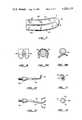
- FIG. 1is a perspective view, partly in section, of a dental scaling instrument
- FIG. 2is a longitudinal cross-sectional view of the dental scaler of FIG. 1;
- FIG. 3is a cross-sectional view of the vibratory driving mechanism of the dental scaler of FIG. 2 taken along line 3--3;
- FIG. 4is a side elevational view of a scaler tip of this invention.
- FIG. 5is a cross-sectional view of the scaler tip of FIG. 4 taken along line 5--5;
- FIGS. 6 and 7are enlarged fragmentary views showing, in perspective, two suitable free ends for the scaler tips of this invention.
- FIG. 8is a side elevational view of a pair of human incisor teeth with the scaler tip of FIG. 4, shown in section, positioned therebetween;
- FIGS. 9A and Bare top sectional views of human teeth showing various uses of a scaler tip of this invention.
- FIG. 10is a side elevational view of another embodiment of this invention illustrating a multi-planar scaler tip
- FIG. 11is a front elevational view of the scaler tip shown in FIG. 10;
- FIG. 12is a side elevational view of a further scaler tip of the invention wherein the tip has a "safe" side;
- FIG. 13is a cross-sectional view of the scaler tip of FIG. 12 taken along line 13--13.
- a dental scaling instrument 10comprising a handle 12 which includes a barrel 14 and a neck 16. Attached to the distal end 18 of handle 12 is a nose piece 20 having an outer knurled wall 22. Secured within nose piece 20 is a shank 24 of a work tool 26 having a configuration of a curved scaler tip having a terminal or free end 28. As shown in detail in the cross-sectional view of FIG. 2, handle 12 provides an elongated housing or casing within which are mounted resilient support means comprising a first or front resilient support bushing 30 and a second or rear resilient support bushing 32.
- a vibratable shaftin the form of a tube 34 which passes through axially disposed openings 36 and 38, respectively, in bushings 30 and 32. Substantial axial movement of tube 34 is prevented by first and second flanges 40 and 42 which rest against bushings 30 and 32, respectively.
- First support bushing 30is retained within the elongated casing by neck 16 which is threadedly engaged with inner wall portion 44 at distal end 18 of handle 12.
- cap 46which is threadedly engaged with an inner wall portion 48 at proximal end 50, retains second support bushing 32 within the elongated casing provided by handle 12.
- a sleeve-like rotor 52Disposed about a mid-portion of tube 34 is a sleeve-like rotor 52. As shown in FIG. 2, rotor 52 is disposed substantially coaxially with respect to tube 34, there being annular gaps 54 established between annular-shaped end portions 56 of rotor 52 and adjacent portions of side wall 57 of tube 34. In an actual assembly with rotor 52 at rest, rotor 52 will be supported upon tube 34 so that a portion of each of the annular ends 56 will rest upon side wall portions of tube 34. Located in side wall portions of tube 34 is a plurality of outlet ports 58 which connect passageway 60 of tube 34 to a chamber 61 defined by inner wall 62 of rotor 52 and an adjacent portion of tube side wall 57.
- a fluid mediumsuch as compressed air
- a fluid mediumsuch as compressed air
- a sourcenot shown
- the flow of compressed airpasses into fluid media inlet port 68 and through passageway 60 to fluid media outlet ports 58.
- the flow of compressed air which exhausts through outlet ports 58fills chamber 61.
- the force of impact of the airflows on inner wall 62 of rotor 52 urges rotor 52 to rotate rapidly about tube 34.
- each of outlet ports 58has an axis which is offset or spaced at a distance from the longitudinal axis of tube 34, such that each port axis does not intersect the axis of tube 34.
- each of ports 58directs a jet of air at a glancing angle with respect to the inner wall 62 of rotor 52 so as to impart rotary movement to rotor 52.
- outlet ports 58are preferably angled with respect to a plane which is perpendicular to tube 34 and which bisects rotor 52, so that air discharged from half of the plurality of ports 58 imparts a component of force tending to move rotor 52 in the distal direction, while flows of air discharged from the other half of the plurality of ports 58 impart a component of force tending to move rotor 52 in the proximal direction.
- the airAfter imparting rotary movement to rotor 52, the air exhausts from chamber 61 through fluid media outlet ports as provided by annular gaps 54 defined by annular end portions 56 and tube side wall 57. The air is further exhausted from the interior of barrel 14 through exhaust ports 70 disposed circumferentially about a rearward portion 72 of barrel 14. Stop means comprising annular-shaped guides 74 are affixed to tube 34 by set screws 76. Guides 74 are positioned adjacent either end of rotor 52 so as to limit movement of rotor 52 in the axial direction along tube 34.
- the speed of revolution of rotor 52 about tube 34is generally dependent upon the size, number and angles of incidence of the air streams discharged from outlet ports 58, and the velocity thereof.
- a description of the manner in which the spinning rotor 52 imparts vibration to tube 34may be found in the aforementioned U.S. Pat. No. Re. 29,687, the disclosure of which is incorporated herein by reference.
- the mode of vibration as evidenced by a trace of movement of a cross-section of tip 26, taken as shown in FIG. 5,may vary from a circular to an ellipsoidal pattern.
- the particular pattern traced and the amplitude of vibrationis believed to be dependent upon the mass of tip 26, its configuration in cross-section, the vibratory mode of tube 34 and the amount of energy transferred to tip 26 from tube 34.
- scaler tip 26has a connectable end portion 90 adapted to be secured to a dental instrument, a working free end portion 94 and a working mid-portion 92.
- End portion 90comprises a nose piece or fingergrip 20 having a boss portion 96 to which is affixed a stud 98 having a threaded portion 100.
- Threaded portion 100operatively secures scaler tip 26 to tube 34.
- Scaler mid-portion 92includes a shank 24 having a generally circular cross-section and which extends into and is frictionally engaged with nose piece 20.
- Shank 24comprises about one-quarter the length of mid portion 92, the balance of mid portion 92 having a curved, elongated configuration with four sides 102.
- a cross-section taken at any point along and substantially perpendicular to the longitudinal axis of scaler mid portion 92has a configuration of an equilateral, four sided figure. As shown in FIG. 5, the cross-section preferably has the shape of a diamond, i.e., a square tilted on one of its edges.
- Scaler tip 26also includes a working free end portion 94 having a terminal end 28, as shown in FIG. 4.
- the curved free end portion 94generally lies in a plane passing through the longitudinal dimension of scaler tip 26 and can be symmetrical about that plane.
- Free end 94 and a part of mid-portion 92are curved so as to form a concave working edge 104 as provided by a first junction or intersection of two adjacent sides 102 and a convex working edge 106 as provided by a second junction or intersection of two other adjacent sides 102, the first and second junctions being in opposed relationship.
- the described plane of symmetrywill thus preferably pass through the two opposed junctions formed by the intersection of different pairs of two of four sides 102.
- a pair of lateral working edges 108is provided by opposed third and fourth junctions or intersections as established by the junctions of pairs of opposed sides 102, portions of which third and fourth junctions lie in a plane substantially perpendicular to the first defined plane containing the free end.
- Each scaler edge 104, 106 and 108is curved as shown in in FIGS. 6 and 7, each curve having a radius of curvature in the range of about 0.001 inch to about 0.005 inch. Preferably, each curve has a radius of curvature in the range of about 0.001 inch to about 0.002 inch. It has been found that a scaler having curved edges as specified provides efficient scaling of teeth with minimal damage to teeth and adjacent tissue.
- free end 94may also be curved away from the longitudinal plane containing curved intermediate portion 92 so that access may be gained to specific regions of the oral cavity.
- the particular curvature of free end 94will vary with the nature of the region in which the work is to be performed.
- a very useful configurationis to have free end 94 lie in a plane perpendicular (or substantially perpendicular) to the plane containing shank 24 and the part of curved portion 92 adjacent thereto.
- free end portion 94 of scaler tip 26has a rounded terminal end 28, as indicated at surface "A" of FIG. 6 and at surface "B" of FIG. 7.
- the radius of curvature of rounded terminal end 28may range from about 0.005 inch to about 0.02 inch, and preferably, about 0.007 inch to about 0.010 inch.
- Terminal end 28may be quite "flat” as shown in FIG. 6 or more highly curved as shown in FIG. 7, or may be in the form of a portion of a perfect spherical shape, or could, as well, have a hyperbolic shape, or a parabolic shape, or other smooth curve.
- One advantage provided by rounded terminal end 28is that the likelihood of damage to tooth dentin, cementum or gums is materially reduced as compared with use of a sharp pointed terminal end.
- the inactive edges of the scaler tip of the inventioncan be connected by smooth, convex surfaces.
- Such convex surfacespresent "safe" surfaces away from working edges and permit the use of tips as described in regions of the oral cavity which contain sensitive tissues or in which the potential for damage is high.
- FIGS. 12 and 13wherein lateral working edge 108 is formed by the intersection of surfaces 102.
- a substantial portion of working edge 108lies in a first plane substantially perpendicular to a second plane passing through the longitudinal dimension of scaler tip 26 and in which curved free end 94 lies.
- the remaining portion of edge 108extends laterally along the side of curved free end 94.
- the non-intersecting edges of surfaces 102are joined by convex surface 116, which presents a smooth surface away from working edge 108.
- Working edge 108can be displaced ⁇ 15 degrees from the perpendicular plane without substantially affecting the scaling effectiveness of the tip. It is preferred, however, to keep working edge 108 within ⁇ 10 degrees of the perpendicular plane. Such variation also has been found acceptable when the working edge lies substantially in the plane passing through the longitudinal dimension of tip 26 and in which curved free end 94 lies. Typically, the plane passing through the longitudinal dimension and in which free end 94 lies bisects the angle formed by the sides intersecting at the working edge, when the working edge is on the inner or outer radii of the curved free end. Such symmetry presents favorable mass distribution for vibratory modes manifested by the Sertich-type scalers which results in rapid cleaning and scaling while maintaining good tactile control and sensitivity for the operator.
- lateral edges 108provide symmetrical scaling on all sides of a tooth and especially provide very good interproximal scaling. It is especially an advantage of the present invention that the circular or ellipsoidal motion of the scaler tip, in combination with the diamond-shaped cross-sectional configuration, provides very efficient and uniform scaling action of deposits from teeth.
- a second feature of the scaler tipis provided by the curved work surfaces.
- concave working edge 104allows cleaning of the sharp curves of teeth as depicted in FIG. 9.
- Concave edge 104is suited for cleaning the contours of molars, as shown in FIG. 9A.
- Convex edge 106is useful for cleaning and for removing stain from anterior buccal surfaces as shown in FIG. 9B.
- the tips of this inventioncan be utilized with a dental scaler or vibratory device of the type described in Sertich U.S. Pat. No. Re. 29,687 or copending application Ser. No. 91,016, entitled “Rotor Driven Vibratory Device Having Rotor Centralization Means and Vibrational Mode Selection Means Associated Therewith,” filed concurrently herewith.
- a dental scaler or vibratory devicecan be modified in accordance with the teachings of any or all of copending applications Ser. No. 12,631, filed Feb. 16, 1979; Ser. No. 26,378, filed Apr. 2, 1979; and application Ser. No. 91,012, entitled “Vibratory Device Having Tool Assembly With Fluid Transport Means,” filed concurrently herewith.
- the above applicationsare incorporated herein by reference to the extent necessary to supplement or complete the disclosure hereof.
- the scaler tip of this inventioninclude both the curved edges and the rounded tip, either can be used independently if desired.
Landscapes
- Health & Medical Sciences (AREA)
- Dentistry (AREA)
- Epidemiology (AREA)
- Life Sciences & Earth Sciences (AREA)
- Animal Behavior & Ethology (AREA)
- General Health & Medical Sciences (AREA)
- Public Health (AREA)
- Veterinary Medicine (AREA)
- Oral & Maxillofacial Surgery (AREA)
- Dental Tools And Instruments Or Auxiliary Dental Instruments (AREA)
Abstract
Description
Claims (61)
Priority Applications (7)
| Application Number | Priority Date | Filing Date | Title |
|---|---|---|---|
| US06/091,018US4283175A (en) | 1979-11-05 | 1979-11-05 | Dental scaler having scaling tip with rounded edge work surfaces particularly suitable for circular or ellipsoidal patterns of vibration |
| CA000363939ACA1160080A (en) | 1979-11-05 | 1980-11-04 | Dental scaler having scaling tip with rounded edge work surfaces particularly suitable for circular or ellipsoidal patterns of vibration |
| AT80303923TATE6198T1 (en) | 1979-11-05 | 1980-11-04 | CLEANING TIP FOR A DEVICE FOR REMOVING TARTAR. |
| JP15394180AJPS5683340A (en) | 1979-11-05 | 1980-11-04 | Scaler chip |
| ZA00806802AZA806802B (en) | 1979-11-05 | 1980-11-04 | Dental scaler |
| EP80303923AEP0028530B1 (en) | 1979-11-05 | 1980-11-04 | Scaling tip for a dental scaler |
| DE8080303923TDE3066631D1 (en) | 1979-11-05 | 1980-11-04 | Scaling tip for a dental scaler |
Applications Claiming Priority (1)
| Application Number | Priority Date | Filing Date | Title |
|---|---|---|---|
| US06/091,018US4283175A (en) | 1979-11-05 | 1979-11-05 | Dental scaler having scaling tip with rounded edge work surfaces particularly suitable for circular or ellipsoidal patterns of vibration |
Publications (1)
| Publication Number | Publication Date |
|---|---|
| US4283175Atrue US4283175A (en) | 1981-08-11 |
Family
ID=22225403
Family Applications (1)
| Application Number | Title | Priority Date | Filing Date |
|---|---|---|---|
| US06/091,018Expired - LifetimeUS4283175A (en) | 1979-11-05 | 1979-11-05 | Dental scaler having scaling tip with rounded edge work surfaces particularly suitable for circular or ellipsoidal patterns of vibration |
Country Status (7)
| Country | Link |
|---|---|
| US (1) | US4283175A (en) |
| EP (1) | EP0028530B1 (en) |
| JP (1) | JPS5683340A (en) |
| AT (1) | ATE6198T1 (en) |
| CA (1) | CA1160080A (en) |
| DE (1) | DE3066631D1 (en) |
| ZA (1) | ZA806802B (en) |
Cited By (44)
| Publication number | Priority date | Publication date | Assignee | Title |
|---|---|---|---|---|
| US4731019A (en)* | 1984-06-04 | 1988-03-15 | Howard Martin | Diamond coated scaler dental instrument for ultrasonic operation |
| US5355587A (en)* | 1991-04-17 | 1994-10-18 | Suzuki Motor Corporation | Ultrasonic cutter |
| US5419703A (en)* | 1988-02-18 | 1995-05-30 | Dentsply Research & Development Corp. | Method of subgingival scaling and lavage |
| US5567153A (en)* | 1994-08-25 | 1996-10-22 | Dentsply Research & Development Corp. | Transducer activated tool tip |
| US5577911A (en)* | 1986-02-04 | 1996-11-26 | Garfinkel; Leonard M. | Ultrasonically driven curette for periodontal curettage |
| US5749727A (en)* | 1994-06-30 | 1998-05-12 | Dentsply Research & Development Corp. | Transducer activated subgingival tool tip |
| US5971758A (en)* | 1997-01-14 | 1999-10-26 | Kaltenbach & Voigt Gmbh & Co. | Tool for the preparation, with removal of material, of a lateral cavity in a tooth |
| US6030212A (en)* | 1996-09-27 | 2000-02-29 | Dentsply Research & Development Corp. | Stacking reservoir and scaler system |
| US6086369A (en)* | 1997-01-13 | 2000-07-11 | Parkell Products, Inc. | Ultrasonic dental scaler insert |
| US6106291A (en)* | 1998-12-15 | 2000-08-22 | Temple University Of The Commonwealth System Of Higher Education | Selective dentin caries excavator |
| WO2000057806A1 (en)* | 1999-03-26 | 2000-10-05 | Harrel Stephen K | Abrasive tool having safe and active areas |
| US6149430A (en)* | 1998-02-20 | 2000-11-21 | Ora Innovations, Inc. | Integrally molded dental appliance and process for its manufacture |
| US6224379B1 (en) | 1998-10-02 | 2001-05-01 | Trustees Of Tufts College | Method for shaping an adhesive material |
| US6309400B2 (en)* | 1998-06-29 | 2001-10-30 | Ethicon Endo-Surgery, Inc. | Curved ultrasonic blade having a trapezoidal cross section |
| US6347941B1 (en) | 2001-02-23 | 2002-02-19 | Temple University Of The Commonwealth System Of Higher Education | Partial dentin caries excavator |
| US20020072035A1 (en)* | 1999-06-04 | 2002-06-13 | Dentsply International Inc. | Microendodontics ultrasonic surgical dental tool having water port and method of making same |
| WO2003070121A1 (en)* | 2002-02-15 | 2003-08-28 | Earth City Technologies, Inc. | Dental instruments for use with ultrasonic handpieces |
| US6660017B2 (en) | 1998-06-29 | 2003-12-09 | Ethicon Endo-Surgery, Inc. | Balanced ultrasonic blade including a singular balance asymmetry |
| US6716028B2 (en) | 2000-08-04 | 2004-04-06 | Hu-Friedy Mfg. Co., Inc. | Ultrasonic swivel insert |
| US6726531B1 (en) | 1999-03-26 | 2004-04-27 | Stephen K. Harrel | Abrasive tool having safe and active areas |
| US6811399B2 (en) | 2001-07-27 | 2004-11-02 | Hu-Friedy Mfg. Co., Inc. | Torque lock for ultrasonic swivelable inserts and method |
| US20040265776A1 (en)* | 2003-03-13 | 2004-12-30 | Tipton David W. | Ultrasonic insert with internal flow channel |
| US6910889B1 (en)* | 2000-11-02 | 2005-06-28 | San Diego Swiss Machining, Inc. | Ultrasonic surgical dental tool having a rasp tip |
| WO2005102204A2 (en) | 2004-06-18 | 2005-11-03 | Satelec | Insert for ultrasonic burr-drill unit |
| USD540945S1 (en) | 2004-02-18 | 2007-04-17 | Young Os, Lc | Periodontal scaling tip for ultrasonic dental handpiece |
| US20080293008A1 (en)* | 2005-02-02 | 2008-11-27 | Pascal Regere | Dental Treatment Apparatus With Automatic Tip Recognition |
| US20090208903A1 (en)* | 2004-06-21 | 2009-08-20 | Straumann Holding Ag | Method for manufacturing disposable rotary cutting tools and disposable rotary tool for dental or medical applications |
| US20100036535A1 (en)* | 2006-11-16 | 2010-02-11 | James Feine | Tip-based computer controlled system for a hand-held dental delivery device |
| US20110112466A1 (en)* | 2009-11-11 | 2011-05-12 | Ramon Carsola Dimalanta | Extended Point Phacoemulsification Tip |
| WO2011070782A1 (en) | 2009-12-10 | 2011-06-16 | Yugen Kaisha Siesta | Ultrasonic scaler tip |
| USD660429S1 (en)* | 2010-09-18 | 2012-05-22 | Ferton Holding S.A. | Tip for a dental scaler |
| US8202087B2 (en) | 2004-10-20 | 2012-06-19 | Patrick Lesage | Grinding tip for a vibrational dental instrument |
| US8623040B2 (en) | 2009-07-01 | 2014-01-07 | Alcon Research, Ltd. | Phacoemulsification hook tip |
| WO2014006579A2 (en) | 2012-07-03 | 2014-01-09 | Eric Chevalier | Dental tool comprising a versatile tip |
| USD718859S1 (en)* | 2013-05-03 | 2014-12-02 | American Eagle Instruments, Inc. | Dental scaler |
| US9050161B2 (en) | 2011-04-29 | 2015-06-09 | James S. Feine | Energy harvesting insert for an ultrasonic handpiece with electrical device |
| US9421072B2 (en) | 2010-03-12 | 2016-08-23 | Societe Pour La Conception Des Applications Des Techniques Electroniques | Vibratory instrument with an interchangeable tool |
| US9788925B2 (en) | 2009-08-19 | 2017-10-17 | Vicky L Moran | Transducer activated tool with water conduit |
| USD820451S1 (en)* | 2017-01-26 | 2018-06-12 | American Eagle Instruments, Llc | Dental scaler |
| US10020679B2 (en) | 2011-04-29 | 2018-07-10 | James Feine | Handheld electrical device system and method |
| USD831827S1 (en)* | 2017-08-24 | 2018-10-23 | Onvi, Inc. | Dental scalar |
| USD836777S1 (en)* | 2017-08-24 | 2018-12-25 | Onvi, Inc. | Dental scaler with mirror |
| US10258505B2 (en) | 2010-09-17 | 2019-04-16 | Alcon Research, Ltd. | Balanced phacoemulsification tip |
| US11058449B2 (en) | 2015-08-12 | 2021-07-13 | Reach Surgical, Inc. | Curved ultrasonic surgical blade |
Families Citing this family (4)
| Publication number | Priority date | Publication date | Assignee | Title |
|---|---|---|---|---|
| JPS60156445A (en)* | 1983-04-30 | 1985-08-16 | 隈部 まさる | Air type tartar removing device for tooth gum |
| JPH0272133U (en)* | 1988-11-21 | 1990-06-01 | ||
| EP0654980B1 (en) | 1992-08-12 | 1998-09-09 | Braun Aktiengesellschaft | Cleaning tool and electrically driven tooth-cleaning instrument using such a tool |
| DE10008588C1 (en)* | 2000-02-24 | 2001-08-16 | Thomas Flemmig | Vibrating tip for a dental tooth cleaning appliance has a flat working zone with hemisphere projections in a curve to reach the tooth roots under the gum to remove scale |
Citations (2)
| Publication number | Priority date | Publication date | Assignee | Title |
|---|---|---|---|---|
| US3817141A (en)* | 1971-11-24 | 1974-06-18 | S Simonetti | Ultrasonically driven cutting knife and method and apparatus for cutting a soft yielding bakery product |
| US3930173A (en)* | 1971-06-15 | 1975-12-30 | Surgical Design Corp | Ultrasonic transducers |
Family Cites Families (5)
| Publication number | Priority date | Publication date | Assignee | Title |
|---|---|---|---|---|
| NL106732C (en)* | 1955-03-08 | |||
| US3552022A (en)* | 1968-07-05 | 1971-01-05 | Axel Torbjorn Axelsson | Apparatus for cleaning or polishing of teeth |
| US3660902A (en)* | 1970-04-24 | 1972-05-09 | A T Axelsson | Apparatus for cleaning or polishing of teeth |
| US3703037A (en)* | 1970-06-25 | 1972-11-21 | Seymour Robinson | Ultrasonic dental hand-piece with detachable treatment tools |
| US3811190A (en)* | 1973-05-29 | 1974-05-21 | A Sertich | Air-vibrator dental scaler |
- 1979
- 1979-11-05USUS06/091,018patent/US4283175A/ennot_activeExpired - Lifetime
- 1980
- 1980-11-04EPEP80303923Apatent/EP0028530B1/ennot_activeExpired
- 1980-11-04ATAT80303923Tpatent/ATE6198T1/enactive
- 1980-11-04ZAZA00806802Apatent/ZA806802B/enunknown
- 1980-11-04CACA000363939Apatent/CA1160080A/ennot_activeExpired
- 1980-11-04DEDE8080303923Tpatent/DE3066631D1/ennot_activeExpired
- 1980-11-04JPJP15394180Apatent/JPS5683340A/enactiveGranted
Patent Citations (2)
| Publication number | Priority date | Publication date | Assignee | Title |
|---|---|---|---|---|
| US3930173A (en)* | 1971-06-15 | 1975-12-30 | Surgical Design Corp | Ultrasonic transducers |
| US3817141A (en)* | 1971-11-24 | 1974-06-18 | S Simonetti | Ultrasonically driven cutting knife and method and apparatus for cutting a soft yielding bakery product |
Cited By (76)
| Publication number | Priority date | Publication date | Assignee | Title |
|---|---|---|---|---|
| US4731019A (en)* | 1984-06-04 | 1988-03-15 | Howard Martin | Diamond coated scaler dental instrument for ultrasonic operation |
| US5577911A (en)* | 1986-02-04 | 1996-11-26 | Garfinkel; Leonard M. | Ultrasonically driven curette for periodontal curettage |
| US5419703A (en)* | 1988-02-18 | 1995-05-30 | Dentsply Research & Development Corp. | Method of subgingival scaling and lavage |
| US5355587A (en)* | 1991-04-17 | 1994-10-18 | Suzuki Motor Corporation | Ultrasonic cutter |
| US5749727A (en)* | 1994-06-30 | 1998-05-12 | Dentsply Research & Development Corp. | Transducer activated subgingival tool tip |
| US5567153A (en)* | 1994-08-25 | 1996-10-22 | Dentsply Research & Development Corp. | Transducer activated tool tip |
| US6030212A (en)* | 1996-09-27 | 2000-02-29 | Dentsply Research & Development Corp. | Stacking reservoir and scaler system |
| US6293793B1 (en) | 1996-09-27 | 2001-09-25 | Dentsply Research & Development Corp. | Stackable reservoir and scaler system |
| US6086369A (en)* | 1997-01-13 | 2000-07-11 | Parkell Products, Inc. | Ultrasonic dental scaler insert |
| US5971758A (en)* | 1997-01-14 | 1999-10-26 | Kaltenbach & Voigt Gmbh & Co. | Tool for the preparation, with removal of material, of a lateral cavity in a tooth |
| US6149430A (en)* | 1998-02-20 | 2000-11-21 | Ora Innovations, Inc. | Integrally molded dental appliance and process for its manufacture |
| US7758600B2 (en) | 1998-06-29 | 2010-07-20 | Ethicon Endo-Surgery, Inc. | Balanced ultrasonic end effector |
| US6309400B2 (en)* | 1998-06-29 | 2001-10-30 | Ethicon Endo-Surgery, Inc. | Curved ultrasonic blade having a trapezoidal cross section |
| US20020004665A1 (en)* | 1998-06-29 | 2002-01-10 | Beaupre Jean M. | Curved ultrasonic blade having a trapezoidal cross section |
| US7300446B2 (en) | 1998-06-29 | 2007-11-27 | Ethicon Endo-Surgery, Inc. | Curved ultrasonic end effector |
| US20080051814A1 (en)* | 1998-06-29 | 2008-02-28 | Beaupre Jean M | Balanced ultrasonic end effector |
| US20100262173A1 (en)* | 1998-06-29 | 2010-10-14 | Beaupre Jean M | Balanced ultrasonic end effector |
| US6660017B2 (en) | 1998-06-29 | 2003-12-09 | Ethicon Endo-Surgery, Inc. | Balanced ultrasonic blade including a singular balance asymmetry |
| US8021381B2 (en) | 1998-06-29 | 2011-09-20 | Ethicon Endo-Surgery, Inc. | Balanced ultrasonic end effector |
| US8617194B2 (en) | 1998-06-29 | 2013-12-31 | Ethicon Endo-Surgery, Inc. | Balanced ultrasonic end effector |
| US6224379B1 (en) | 1998-10-02 | 2001-05-01 | Trustees Of Tufts College | Method for shaping an adhesive material |
| US6106291A (en)* | 1998-12-15 | 2000-08-22 | Temple University Of The Commonwealth System Of Higher Education | Selective dentin caries excavator |
| US6872125B2 (en) | 1999-03-26 | 2005-03-29 | Stephen K. Harrel | Tool for smoothing a workpiece |
| US6726531B1 (en) | 1999-03-26 | 2004-04-27 | Stephen K. Harrel | Abrasive tool having safe and active areas |
| WO2000057806A1 (en)* | 1999-03-26 | 2000-10-05 | Harrel Stephen K | Abrasive tool having safe and active areas |
| US20040176016A1 (en)* | 1999-03-26 | 2004-09-09 | Harrel Stephen K. | Tool for smoothing a workpiece |
| US7140878B2 (en) | 1999-06-04 | 2006-11-28 | Dentsply International, Inc. | Microendodontics ultrasonic surgical dental tool having water port and method of making same |
| US6817862B2 (en) | 1999-06-04 | 2004-11-16 | Dentsply International, Inc. | Ultrasonic dental tool having quick change connector and method of making same |
| US20040241608A1 (en)* | 1999-06-04 | 2004-12-02 | Dentsply International, Inc. | Microendodontics ultrasonic surgical dental tool having water port and method of making same |
| US20020072035A1 (en)* | 1999-06-04 | 2002-06-13 | Dentsply International Inc. | Microendodontics ultrasonic surgical dental tool having water port and method of making same |
| US6810585B2 (en) | 1999-06-04 | 2004-11-02 | Dentsply International, Inc. | Method of making a microendodontics ultrasonic surgical dental tool having water port |
| US6716028B2 (en) | 2000-08-04 | 2004-04-06 | Hu-Friedy Mfg. Co., Inc. | Ultrasonic swivel insert |
| US7011520B2 (en) | 2000-08-04 | 2006-03-14 | Hu-Friedy Mfg. Co., Inc. | Two part ultrasonic swivel insert, with one part rotatable relative to the other |
| US20040191724A1 (en)* | 2000-08-04 | 2004-09-30 | Rahman Anisur Mithu | Ultrasonic swivel insert |
| US6910889B1 (en)* | 2000-11-02 | 2005-06-28 | San Diego Swiss Machining, Inc. | Ultrasonic surgical dental tool having a rasp tip |
| US6347941B1 (en) | 2001-02-23 | 2002-02-19 | Temple University Of The Commonwealth System Of Higher Education | Partial dentin caries excavator |
| US6811399B2 (en) | 2001-07-27 | 2004-11-02 | Hu-Friedy Mfg. Co., Inc. | Torque lock for ultrasonic swivelable inserts and method |
| US6722882B2 (en)* | 2002-02-15 | 2004-04-20 | Earth City Technologies, Inc. | Dental instruments for use with ultrasonic handpieces |
| WO2003070121A1 (en)* | 2002-02-15 | 2003-08-28 | Earth City Technologies, Inc. | Dental instruments for use with ultrasonic handpieces |
| AU2003211075B2 (en)* | 2002-02-15 | 2009-01-08 | Young Os Llc | Dental instruments for use with ultrasonic handpieces |
| US20040265776A1 (en)* | 2003-03-13 | 2004-12-30 | Tipton David W. | Ultrasonic insert with internal flow channel |
| USD558346S1 (en) | 2004-02-18 | 2007-12-25 | Young Os, Lc | Periodontal scaling tip for ultrasonic dental handpiece |
| USD540945S1 (en) | 2004-02-18 | 2007-04-17 | Young Os, Lc | Periodontal scaling tip for ultrasonic dental handpiece |
| USD558347S1 (en) | 2004-02-18 | 2007-12-25 | Young Os, Lc | Periodontal scaling tip for ultrasonic dental handpiece |
| FR2871677A1 (en) | 2004-06-18 | 2005-12-23 | Satelec Soc | INSERT FOR ULTRASONIC DENTAL DEVICE |
| US20070254262A1 (en)* | 2004-06-18 | 2007-11-01 | Jean-Claude Doussin | Insert for Ultrasonic Burr-Drill Unit |
| US10213276B2 (en)* | 2004-06-18 | 2019-02-26 | Societe Pour La Conceptions Des Applications Des Techniques Electroniques (Satelec) | Insert for ultrasonic burr-drill unit |
| WO2005102204A2 (en) | 2004-06-18 | 2005-11-03 | Satelec | Insert for ultrasonic burr-drill unit |
| US20090208903A1 (en)* | 2004-06-21 | 2009-08-20 | Straumann Holding Ag | Method for manufacturing disposable rotary cutting tools and disposable rotary tool for dental or medical applications |
| US9962167B2 (en) | 2004-06-21 | 2018-05-08 | Straumann Holding Ag | Method for manufacturing disposable rotary cutting tools and disposable rotary tool for dental or medical applications |
| US9770247B2 (en)* | 2004-06-21 | 2017-09-26 | Straumann Holding Ag | Method for manufacturing disposable rotary cutting tools and disposable rotary tool for dental or medical applications |
| US8202087B2 (en) | 2004-10-20 | 2012-06-19 | Patrick Lesage | Grinding tip for a vibrational dental instrument |
| EP1848363B1 (en) | 2005-02-02 | 2018-04-11 | Societe Pour La Conception Des Applications Des Techniques Electroniques | Dental treatment apparatus with automatic insert recognition |
| US20080293008A1 (en)* | 2005-02-02 | 2008-11-27 | Pascal Regere | Dental Treatment Apparatus With Automatic Tip Recognition |
| US8758011B2 (en) | 2005-02-02 | 2014-06-24 | Societe Pour La Conceptions Des Applications Des Techniques Electroniques (Satelec) | Dental treatment appliance with automatic tip recognition |
| US8204612B2 (en) | 2006-11-16 | 2012-06-19 | James Feine | Tip-based computer controlled system for a hand-held dental delivery device |
| US20100036535A1 (en)* | 2006-11-16 | 2010-02-11 | James Feine | Tip-based computer controlled system for a hand-held dental delivery device |
| US8623040B2 (en) | 2009-07-01 | 2014-01-07 | Alcon Research, Ltd. | Phacoemulsification hook tip |
| US9233021B2 (en) | 2009-07-01 | 2016-01-12 | Alcon Research, Ltd. | Phacoemulsification hook tip |
| US9788925B2 (en) | 2009-08-19 | 2017-10-17 | Vicky L Moran | Transducer activated tool with water conduit |
| US20110112466A1 (en)* | 2009-11-11 | 2011-05-12 | Ramon Carsola Dimalanta | Extended Point Phacoemulsification Tip |
| US20120237895A1 (en)* | 2009-12-10 | 2012-09-20 | Yugen Kaisha Seista | Ultrasonic scaler tip |
| EP2509529A4 (en)* | 2009-12-10 | 2014-06-04 | Yugen Kaisha Siesta | ULTRASONIC DETECTOR TOOL |
| US9351802B2 (en)* | 2009-12-10 | 2016-05-31 | Yugen Kaisha Siesta | Ultrasonic scaler tip |
| WO2011070782A1 (en) | 2009-12-10 | 2011-06-16 | Yugen Kaisha Siesta | Ultrasonic scaler tip |
| US9421072B2 (en) | 2010-03-12 | 2016-08-23 | Societe Pour La Conception Des Applications Des Techniques Electroniques | Vibratory instrument with an interchangeable tool |
| US10258505B2 (en) | 2010-09-17 | 2019-04-16 | Alcon Research, Ltd. | Balanced phacoemulsification tip |
| USD660429S1 (en)* | 2010-09-18 | 2012-05-22 | Ferton Holding S.A. | Tip for a dental scaler |
| US10020679B2 (en) | 2011-04-29 | 2018-07-10 | James Feine | Handheld electrical device system and method |
| US9050161B2 (en) | 2011-04-29 | 2015-06-09 | James S. Feine | Energy harvesting insert for an ultrasonic handpiece with electrical device |
| WO2014006579A2 (en) | 2012-07-03 | 2014-01-09 | Eric Chevalier | Dental tool comprising a versatile tip |
| USD718859S1 (en)* | 2013-05-03 | 2014-12-02 | American Eagle Instruments, Inc. | Dental scaler |
| US11058449B2 (en) | 2015-08-12 | 2021-07-13 | Reach Surgical, Inc. | Curved ultrasonic surgical blade |
| USD820451S1 (en)* | 2017-01-26 | 2018-06-12 | American Eagle Instruments, Llc | Dental scaler |
| USD831827S1 (en)* | 2017-08-24 | 2018-10-23 | Onvi, Inc. | Dental scalar |
| USD836777S1 (en)* | 2017-08-24 | 2018-12-25 | Onvi, Inc. | Dental scaler with mirror |
Also Published As
| Publication number | Publication date |
|---|---|
| JPS5683340A (en) | 1981-07-07 |
| EP0028530A1 (en) | 1981-05-13 |
| ATE6198T1 (en) | 1984-03-15 |
| ZA806802B (en) | 1982-06-30 |
| CA1160080A (en) | 1984-01-10 |
| DE3066631D1 (en) | 1984-03-22 |
| EP0028530B1 (en) | 1984-02-15 |
| JPS5757139B2 (en) | 1982-12-03 |
Similar Documents
| Publication | Publication Date | Title |
|---|---|---|
| US4283175A (en) | Dental scaler having scaling tip with rounded edge work surfaces particularly suitable for circular or ellipsoidal patterns of vibration | |
| US4283174A (en) | Dental scaler having scaling tip particularly suitable for circular or ellipsoidal patterns of vibration | |
| US4315742A (en) | Vibratory device having tool assembly with fluid transport means | |
| US5772434A (en) | Ultrasonic tooth cleaner | |
| US5827064A (en) | Orbitally or reciprocally vibrating method for interproximal plaque removal | |
| US3058218A (en) | Methods and means for driving small diameter shafts at high rotational speeds | |
| US5236358A (en) | Dental ultrasonic calculus removal apparatus and method | |
| US5002487A (en) | Periodontic tool with triangular vibration path | |
| US4173828A (en) | Interchangeable tool operating apparatus with plural motion | |
| US4260380A (en) | Vibratory device with fluid transport means | |
| KR200365249Y1 (en) | An electric puff | |
| US6030216A (en) | Dentistry hand piece | |
| US5190456A (en) | Air-driven dental scaler | |
| EP0028531B1 (en) | Vibratory device and dental scaler incorporating it | |
| US3241239A (en) | Dental tool drive mechanism | |
| JP2001514923A (en) | Medical or dental instruments and tools for such instruments | |
| WO2022110495A1 (en) | Root canal treatment device | |
| US5577911A (en) | Ultrasonically driven curette for periodontal curettage | |
| EP0261272B1 (en) | Air-driven dental scaler | |
| ATE235859T1 (en) | MEDICAL OR DENTAL HANDPIECE WITH A TOOL FOR MACHINING | |
| EP0015672B1 (en) | Vibratory device, work tool assembly, and dental scaler incorporating them | |
| JP5857277B2 (en) | Dental vibratory handpiece device with endoscope probe | |
| US20220031437A1 (en) | Apparatus and method for dental cleaning | |
| JP6349526B2 (en) | Method of manufacturing brush holder for dental vibratory handpiece | |
| US3526962A (en) | Dental vibrator for scaling teeth |
Legal Events
| Date | Code | Title | Description |
|---|---|---|---|
| AS | Assignment | Owner name:SYNTEX (U.S.A.) INC., 3401 HILLVIEW AVE., PALO ALT Free format text:ASSIGNMENT OF ASSIGNORS INTEREST.;ASSIGNOR:NASH JOHN E.;REEL/FRAME:003848/0921 Effective date:19810407 | |
| STCF | Information on status: patent grant | Free format text:PATENTED CASE | |
| AS | Assignment | Owner name:DEN-TAL-EZ DENTAL PRODUCTS CORP., 1900 RITTENHOUSE Free format text:ASSIGNMENT OF ASSIGNORS INTEREST.;ASSIGNOR:SYNTEX (U.S.A.) INC.;REEL/FRAME:004671/0857 Effective date:19861010 Owner name:DEN-TAL-EZ DENTAL PRODUCTS CORP., A CORP. OF PA.,P Free format text:ASSIGNMENT OF ASSIGNORS INTEREST;ASSIGNOR:SYNTEX (U.S.A.) INC.;REEL/FRAME:004671/0857 Effective date:19861010 | |
| AS | Assignment | Owner name:MERIDIAN BANK, 5 PENN CENTER PLAZA, PHILADELPHIA, Free format text:SECURITY INTEREST;ASSIGNOR:DEN-TAL-EZ DENTAL PRODUCTS CORP.;REEL/FRAME:004826/0156 Effective date:19861020 Owner name:DEN-TAL-EZ, INC. Free format text:SECURITY INTEREST;ASSIGNOR:DEN-TAL-EZ DENTAL PRODUCTS CORP.;REEL/FRAME:004826/0171 Effective date:19861020 Owner name:MERIDIAN BANK,PENNSYLVANIA Free format text:SECURITY INTEREST;ASSIGNOR:DEN-TAL-EZ DENTAL PRODUCTS CORP.;REEL/FRAME:004826/0156 Effective date:19861020 Owner name:MERIDIAN BANK, PENNSYLVANIA Free format text:SECURITY INTEREST;ASSIGNOR:DEN-TAL-EZ DENTAL PRODUCTS CORP.;REEL/FRAME:004826/0156 Effective date:19861020 | |
| AS | Assignment | Owner name:DENTAL-EZ, INC., PENNSYLVANIA Free format text:ASSIGNMENT OF ASSIGNORS INTEREST AS OF JANUARY 26, 1990;ASSIGNORS:DOMINION BANK OF MARYLAND, N.A.;JEFFERSON BANK;DOMINION BANK, N.A.;REEL/FRAME:005919/0959;SIGNING DATES FROM 19910429 TO 19911112 |