US4282762A - Load sensing transducer - Google Patents
Load sensing transducerDownload PDFInfo
- Publication number
- US4282762A US4282762AUS06/088,879US8887979AUS4282762AUS 4282762 AUS4282762 AUS 4282762AUS 8887979 AUS8887979 AUS 8887979AUS 4282762 AUS4282762 AUS 4282762A
- Authority
- US
- United States
- Prior art keywords
- load
- spindle
- end regions
- anvil
- transducer
- Prior art date
- Legal status (The legal status is an assumption and is not a legal conclusion. Google has not performed a legal analysis and makes no representation as to the accuracy of the status listed.)
- Expired - Lifetime
Links
- 230000009977dual effectEffects0.000claimsabstractdescription11
- 230000005489elastic deformationEffects0.000description4
- 238000010586diagramMethods0.000description2
- 238000012986modificationMethods0.000description2
- 230000004048modificationEffects0.000description2
- 230000003321amplificationEffects0.000description1
- 230000001351cycling effectEffects0.000description1
- 238000005259measurementMethods0.000description1
- 238000000034methodMethods0.000description1
- 238000003199nucleic acid amplification methodMethods0.000description1
Images

Classifications
- G—PHYSICS
- G01—MEASURING; TESTING
- G01L—MEASURING FORCE, STRESS, TORQUE, WORK, MECHANICAL POWER, MECHANICAL EFFICIENCY, OR FLUID PRESSURE
- G01L1/00—Measuring force or stress, in general
- G01L1/20—Measuring force or stress, in general by measuring variations in ohmic resistance of solid materials or of electrically-conductive fluids; by making use of electrokinetic cells, i.e. liquid-containing cells wherein an electrical potential is produced or varied upon the application of stress
- G01L1/22—Measuring force or stress, in general by measuring variations in ohmic resistance of solid materials or of electrically-conductive fluids; by making use of electrokinetic cells, i.e. liquid-containing cells wherein an electrical potential is produced or varied upon the application of stress using resistance strain gauges
- G01L1/2206—Special supports with preselected places to mount the resistance strain gauges; Mounting of supports
- G01L1/2231—Special supports with preselected places to mount the resistance strain gauges; Mounting of supports the supports being disc- or ring-shaped, adapted for measuring a force along a single direction
- G01L1/2237—Special supports with preselected places to mount the resistance strain gauges; Mounting of supports the supports being disc- or ring-shaped, adapted for measuring a force along a single direction the direction being perpendicular to the central axis
- G—PHYSICS
- G01—MEASURING; TESTING
- G01L—MEASURING FORCE, STRESS, TORQUE, WORK, MECHANICAL POWER, MECHANICAL EFFICIENCY, OR FLUID PRESSURE
- G01L1/00—Measuring force or stress, in general
- G01L1/20—Measuring force or stress, in general by measuring variations in ohmic resistance of solid materials or of electrically-conductive fluids; by making use of electrokinetic cells, i.e. liquid-containing cells wherein an electrical potential is produced or varied upon the application of stress
- G01L1/22—Measuring force or stress, in general by measuring variations in ohmic resistance of solid materials or of electrically-conductive fluids; by making use of electrokinetic cells, i.e. liquid-containing cells wherein an electrical potential is produced or varied upon the application of stress using resistance strain gauges
- G01L1/225—Measuring circuits therefor
- G01L1/2256—Measuring circuits therefor involving digital counting
Definitions
- This inventionrelates to load sensing apparatus and more particularly to a dual range force transducer for measuring compressive or tensile loads.
- a low capacity transducersuch as a 50 pound strain gauge transducer for measuring a 20 pound load, is not susceptible to electrical noise of this type since its output need not be highly amplified.
- the large capacity transduceris required to measure the stopping torques present in the dynamometer.
- a dual range transducerfor measuring compressive loads and/or tensile loads.
- the transduceris provided with first strain gauges which measure loads, for example, on the order of from 0 to 50 pounds and a second strain gauges which measure loads on the order of, for example, 50 pounds to 5,000 pounds.
- the transducerincludes an annular member having diametrically opposed end regions to which the load or force being measured is applied.
- the first strain gaugesare attached to diametrically opposed sides of the annular member which are spaced between the end regions.
- the side regionsare subject to a elastic deformation.
- An increasing elastic deformation of the side regions as the load increasescauses an increasing output from the first strain gauges. This output is amplified and may be applied through an analog-to-digital converter to a digital load indicator; or from the amplifier directly to a recorder.
- An anvil and a spindleare mounted within the annular member in alignment with the diametrically opposed end regions.
- a spacingis provided between the anvil and the spindle to define a gap which closes when a predetermined load is applied to the end regions. For example, if the first strain gauges are designed to measure from 0 to 50 pounds, then the gap is adjusted to close when a 50 pound load is applied to the end regions. As additional loading is applied to the end regions, this load is transmitted between the anvil and the spindle and no further elastic deformation takes place in the side regions of the annular member. The second strain gauge measures the load or force transmitted between the anvil and the spindle.
- the output of the second strain gaugealso can be amplified and applied to a recorder or digitized and applied to a digital indicator, for example.
- the output of the second strain gaugewill be offset from a true reading by the maximum output, e.g. 50 pounds, from the first strain gauges since the second strain gauge will not begin to indicate an output until the side regions of the annular member are deformed so that the anvil and spindle come into contact with one another.
- highly accurate load indicationsmay be obtained over two widely differing load ranges, such as over a range of 0 to 50 pounds and over a range of from 0 to 5,000 pounds. Since the output of the strain gauges measuring low load levels need not be highly amplified, the low load levels are accurately indicated and are not highly susceptible to error due to electrical noise.
- Another object of the inventionis to provide a load measuring transducer capable of accurately measuring low level loads and also capable of measuring high level loads.
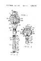
- FIG. 1is a perspective view of a load measuring transducer constructed in accordance with one embodiment of the invention
- FIG. 2is a side elevational view of the transducer of FIG. 1;
- FIG. 3is a cross sectional view taken along line 3--3 of FIG. 2;
- FIG. 4is a fragmentary cross sectional view, similar to FIG. 3, and showing a modified embodiment of the invention
- FIG. 5is a cross sectional view taken along line 5--5 of FIG. 4;
- FIG. 6is a schematic block circuit diagram showing exemplary apparatus for indicating the output from the strain gauges in the transducer of the present invention.
- a two capacity transducer 10is illustrated in accordance with one embodiment of the invention for measuring compressive loads or forces.
- the transducer 10accurately measures loads or forces in a low range of from 0 to 50 pounds and also measures loads in a high range of from 0 to 5,000 pounds.
- the transducer 10may be modified for measuring loads over any desired ranges, as will be readily apparent to those skilled in this art.
- the transducer 10includes an annular member 11 having two diametrically opposed end regions 12 and 13 and two diametrically opposed side regions 14 and 15 spaced between the end regions 12 and 13.
- an anvil 16projects radially inwardly into the annular member 11.
- the end region 12also is provided with a shoulder 17 which defines an outwardly directed blind threaded opening 18.
- the end region 13is provided with a shoulder 19.
- a threaded opening 20extends through the shoulder 19 for receiving a corresponding threaded portion 27 of a spindle 21.
- the spindle 21has an end 22 within the confines of the annular member 11 which defines a small gap 23 with respect to the anvil 16.
- the spindle 21also has an end 24 located external to the annular member 11 and defining a blind threaded opening 25.
- a lock nut 26is provided on the threaded portion 27 of the spindle 21 external to the annular member 11. The nut 26 is tightened against the shoulder 19 to lock the spindle 21 to the annular member 11.
- a first set of strain gauges 28are mounted on the side regions 14 and 15 of the annular member 11.
- the strain gauges 28are selected to measure low level loads which elastically deform the side regions 14 and 15 of the annular member 11, such as loads less than 50 pounds. These loads are applied to the transducer 10 through apparatus (not shown) engaging the threaded opening 18 in the shoulder 17 and the threaded opening 25 in the end 25 of the spindle 21.
- a second strain gauge 30is mounted on or within the spindle 21 in a region 32 between the threaded portion 27 and the spindle end 22 or the strain gauge 30 may be mounted on or within the anvil 16 by techniques known in the art.
- the strain gauge 30measures higher order compressive forces between the anvil 16 and the spindle 21 such as loads up to 5,000 pounds.
- the lower magnitude loadsare not measured by the strain gauge 30 since the gap 23 between the spindle 21 and the anvil 16 will confine all lower level loads to the side regions 14 and 15 of the annular member 11.
- all higher level loadsare measured by the strain gauge 30 since closure of the gap 23 prevents further elastic deformation of the side regions 14 and 15 of the annular member 11.
- the gap 23is adjusted by turning the spindle 21 in the threaded opening 20 in the annular member 11 so that the gap 23 just closes when the maximum load to be measured by the strain gauges 28 is reached. Once the gap 23 closes, no further deformation will take place in the side regions 14 and 15 of the annular member 11 and all additional forces above those required to close the gap 23 are transmitted between the anvil 16 and the spindle 21. As a consequence of the gap 23, the strain gauge 30 will have an output which is offset from a true load indication by the load or force required to close the gap 23, e.g., by 50 pounds. Therefore, the output of the strain gauges 28 must be summed with the output of the strain gauge 30 to obtain an accurate reading in the higher ranges.
- FIGS. 4 and 5a fragmentary cross section illustrated of a modified embodiment of a dual capacity transducer 40.
- the transducer 40is similar to the transducer 10, except that it is capable of measuring either compressive or tensile loads applied between a spindle 41 which engages a threaded opening 42 through a shoulder 43 at one end region 44 of an annular member 45 and a threaded opening 46 in a shoulder 47 at a diametrically opposed end region 48 of the annular member 45.
- the lower end of the spindle 41which is not shown, may be identical to the lower end 24 of the spindle 21 shown in FIGS. 1-3.
- a shaft 49projects radially inwardly from the end region 48 of the annular 45 and has threaded end 50.
- a disc 51is threaded on to the shaft end 50.
- the shaft 49 and the disc 51correspond to the anvil 16 in the previously described transducer 10.
- the spindle 41is provided with an end 52 through which an opening 53 is bored to receive the shaft 49.
- a slot 54is milled in the spindle 41 below the end 52.
- the slot 54is formed to receive the disc 51 and also to allow threading the disc 51 on to the shaft end 50 when the transducer 40 is initially manufactured.
- a gap 55is defined between the disc 51 and the spindle 41 in a direction towards the end region 44 of the annular member 45 and a gap 56 is defined between the disc 51 and the spindle 41 in the direction of the end region 48 of the annular member 45.
- a second strain gauge 57 mounted within the spindle 41will indicate either a compressive or a tensile load on the transducer 40, depending upon the nature of the applied load.
- the gap 55 or the gap 56may be adjusted so that either gap will close when a predetermined compressive or tensile load is applied to the transducer 40. It also should be noted that by providing gaps 55 and 56 on both sides of disc 51, the transducer 40 will be protected from damage should a high load be applied in both directions. In the transducer 10 illustrated in FIGS. 1-3, a high tensile may cause plastic deformation of the side regions 14 and 15 of the annular member 11. Since the gaps 55 and 56 restrict movement of the side regions of the annular member 45 of the transducer 40 shown in FIGS. 4 and 5, such side regions cannot be moved to a point of plastic deformation and, therefore, are protected from damage.
- FIG. 6a schematic block diagram is illustrated of an exemplary circuit 60 for indicating a load measured by the dual range tranducer 10 illustrated in FIGS. 1-3.
- the first or low range strain gauge 28 for the transducer 10has an output applied to an analog-to-digital converter 61 and the second or high range strain gauge 30 has an output applied to an analog-to-digital converter 62.
- a clock 63is provided for periodically cycling both converters 61 and 62.
- the output of the converter 61is stored in a register 64 and the output of the converter 62 is stored in a register 65.
- the contents of the two registers 64 and 65are applied to a summing register 66 and the sum is applied to a conventional digital display 67 which indicates the total load measured by the transducer 10.
- the first strain gauge 28will have an output which will cause the converter 61 to store 50 pounds in the register 64.
- the strain gauge 30will have an output at the same time which will cause the converter 62 to store 2,450 pounds in the register 65.
- the contents of the two registers 64 and 65are added together and stored in the summing register 66 as 2,500 pounds and this load is indicated on the digital display 67.
- the circuit 60has been described in combination with the transducer 10 of FIGS. 1-3, it also will function with the transducer 40 of FIGS. 4 and 5.
- the outputs of the strain gauges 28 and 30 for the transducer 10may be separately amplified and applied to analog meters which cover the appropriate load ranges, e.g. from 0 to 50 pounds for the gauge 28 and from 50 to 5,000 pounds for the gauge 30.
Landscapes
- Physics & Mathematics (AREA)
- General Physics & Mathematics (AREA)
- Measurement Of Length, Angles, Or The Like Using Electric Or Magnetic Means (AREA)
- Measurement Of Force In General (AREA)
Abstract
Description
Claims (5)
Priority Applications (1)
| Application Number | Priority Date | Filing Date | Title |
|---|---|---|---|
| US06/088,879US4282762A (en) | 1979-10-29 | 1979-10-29 | Load sensing transducer |
Applications Claiming Priority (1)
| Application Number | Priority Date | Filing Date | Title |
|---|---|---|---|
| US06/088,879US4282762A (en) | 1979-10-29 | 1979-10-29 | Load sensing transducer |
Publications (1)
| Publication Number | Publication Date |
|---|---|
| US4282762Atrue US4282762A (en) | 1981-08-11 |
Family
ID=22214037
Family Applications (1)
| Application Number | Title | Priority Date | Filing Date |
|---|---|---|---|
| US06/088,879Expired - LifetimeUS4282762A (en) | 1979-10-29 | 1979-10-29 | Load sensing transducer |
Country Status (1)
| Country | Link |
|---|---|
| US (1) | US4282762A (en) |
Cited By (14)
| Publication number | Priority date | Publication date | Assignee | Title |
|---|---|---|---|---|
| US4425808A (en) | 1982-02-26 | 1984-01-17 | The United States Of America As Represented By The Administrator Of The National Aeronautics And Space Administration | Thin film strain transducer |
| US4491027A (en)* | 1983-01-31 | 1985-01-01 | Tetrahedron Associates, Inc. | Wide-range load cell |
| US4498231A (en)* | 1982-02-26 | 1985-02-12 | The United States Of America As Represented By The Administrator Of The National Aeronautics And Space Administration | Thin film strain transducer |
| DE3522453A1 (en)* | 1984-07-12 | 1986-01-23 | Aktiebolaget Sandvik Hard Materials, Stockholm | METHOD AND DEVICE FOR MEASURING SMALL FORCES AND SMALL MOVEMENTS IN A MATERIAL TESTING MACHINE OR OTHER LOADING DEVICE |
| GB2182156A (en)* | 1985-10-25 | 1987-05-07 | Defiant Weighing Limited | Load sensing structure |
| US4706507A (en)* | 1986-02-21 | 1987-11-17 | Horiba Instruments Incorporated | Torque measuring device having dual range load cells |
| EP0181234A3 (en)* | 1984-11-09 | 1989-02-22 | Continental Can Company, Inc. | Applied force monitor for apparatus for forming products from sheet material |
| US5207108A (en)* | 1991-06-07 | 1993-05-04 | Tassic William P | Transducer for sensing tension loading of a conveyor chain |
| US5272924A (en)* | 1991-11-05 | 1993-12-28 | William P. Tassic | System and method for monitoring tension loading of a conveyor chain |
| FR2714283A1 (en)* | 1993-12-15 | 1995-06-30 | Ind Tech Res Inst | Load detector for bone grafts. i.e. spinal vertebrae |
| US5591943A (en)* | 1994-06-10 | 1997-01-07 | Cheng; Liang-Chieh | Weight-sensing member for an electrical suspension weigher |
| US20030029247A1 (en)* | 2001-08-10 | 2003-02-13 | Biedermann Motech Gmbh | Sensor device, in particular for a prosthesis, and prosthesis having such a sensor device |
| US20030102170A1 (en)* | 2001-11-30 | 2003-06-05 | Simons Gerald S. | Standard attachment fittings for wire rope and chain enhanced to also perform load weighing functions |
| CN109855767A (en)* | 2019-02-15 | 2019-06-07 | 武汉理工大学 | A kind of high-precision list component primary and secondary sensor |
Citations (10)
| Publication number | Priority date | Publication date | Assignee | Title |
|---|---|---|---|---|
| US2582886A (en)* | 1948-03-13 | 1952-01-15 | Baldwin Lima Hamilton Corp | Differential load weighing device |
| US2775887A (en)* | 1953-06-11 | 1957-01-01 | Baldwin Lima Hamilton Corp | Load cell type dynamometer with overload protection means |
| US3100290A (en)* | 1961-01-04 | 1963-08-06 | Revere Corp America | Columnar stress sensing member |
| US3240065A (en)* | 1961-07-05 | 1966-03-15 | Taber Instr Corp | Differential pressure transducer |
| US3295086A (en)* | 1964-07-02 | 1966-12-27 | Blh Electronics | Multi-range load cells |
| US3315202A (en)* | 1964-06-02 | 1967-04-18 | Toroid Corp | Load sensing device |
| GB1088345A (en)* | 1966-05-16 | 1967-10-25 | Reidar Storm Vilno | Overload devices for cranes and the like |
| US3872715A (en)* | 1974-02-13 | 1975-03-25 | Krautkramer Branson | Ultrasonic pulse-echo gate circuit |
| US3885427A (en)* | 1972-05-16 | 1975-05-27 | Wirth Gallo & Co | Electronic balance for measuring masses or forces |
| US3911738A (en)* | 1973-05-23 | 1975-10-14 | Hans Werner Fischer | Linearized force measuring apparatus |
- 1979
- 1979-10-29USUS06/088,879patent/US4282762A/ennot_activeExpired - Lifetime
Patent Citations (10)
| Publication number | Priority date | Publication date | Assignee | Title |
|---|---|---|---|---|
| US2582886A (en)* | 1948-03-13 | 1952-01-15 | Baldwin Lima Hamilton Corp | Differential load weighing device |
| US2775887A (en)* | 1953-06-11 | 1957-01-01 | Baldwin Lima Hamilton Corp | Load cell type dynamometer with overload protection means |
| US3100290A (en)* | 1961-01-04 | 1963-08-06 | Revere Corp America | Columnar stress sensing member |
| US3240065A (en)* | 1961-07-05 | 1966-03-15 | Taber Instr Corp | Differential pressure transducer |
| US3315202A (en)* | 1964-06-02 | 1967-04-18 | Toroid Corp | Load sensing device |
| US3295086A (en)* | 1964-07-02 | 1966-12-27 | Blh Electronics | Multi-range load cells |
| GB1088345A (en)* | 1966-05-16 | 1967-10-25 | Reidar Storm Vilno | Overload devices for cranes and the like |
| US3885427A (en)* | 1972-05-16 | 1975-05-27 | Wirth Gallo & Co | Electronic balance for measuring masses or forces |
| US3911738A (en)* | 1973-05-23 | 1975-10-14 | Hans Werner Fischer | Linearized force measuring apparatus |
| US3872715A (en)* | 1974-02-13 | 1975-03-25 | Krautkramer Branson | Ultrasonic pulse-echo gate circuit |
Cited By (18)
| Publication number | Priority date | Publication date | Assignee | Title |
|---|---|---|---|---|
| US4425808A (en) | 1982-02-26 | 1984-01-17 | The United States Of America As Represented By The Administrator Of The National Aeronautics And Space Administration | Thin film strain transducer |
| US4498231A (en)* | 1982-02-26 | 1985-02-12 | The United States Of America As Represented By The Administrator Of The National Aeronautics And Space Administration | Thin film strain transducer |
| US4491027A (en)* | 1983-01-31 | 1985-01-01 | Tetrahedron Associates, Inc. | Wide-range load cell |
| DE3522453A1 (en)* | 1984-07-12 | 1986-01-23 | Aktiebolaget Sandvik Hard Materials, Stockholm | METHOD AND DEVICE FOR MEASURING SMALL FORCES AND SMALL MOVEMENTS IN A MATERIAL TESTING MACHINE OR OTHER LOADING DEVICE |
| EP0181234A3 (en)* | 1984-11-09 | 1989-02-22 | Continental Can Company, Inc. | Applied force monitor for apparatus for forming products from sheet material |
| GB2182156A (en)* | 1985-10-25 | 1987-05-07 | Defiant Weighing Limited | Load sensing structure |
| US4706507A (en)* | 1986-02-21 | 1987-11-17 | Horiba Instruments Incorporated | Torque measuring device having dual range load cells |
| US5207108A (en)* | 1991-06-07 | 1993-05-04 | Tassic William P | Transducer for sensing tension loading of a conveyor chain |
| US5272924A (en)* | 1991-11-05 | 1993-12-28 | William P. Tassic | System and method for monitoring tension loading of a conveyor chain |
| FR2714283A1 (en)* | 1993-12-15 | 1995-06-30 | Ind Tech Res Inst | Load detector for bone grafts. i.e. spinal vertebrae |
| US5456724A (en)* | 1993-12-15 | 1995-10-10 | Industrial Technology Research Institute | Load sensor for bone graft |
| US5591943A (en)* | 1994-06-10 | 1997-01-07 | Cheng; Liang-Chieh | Weight-sensing member for an electrical suspension weigher |
| US20030029247A1 (en)* | 2001-08-10 | 2003-02-13 | Biedermann Motech Gmbh | Sensor device, in particular for a prosthesis, and prosthesis having such a sensor device |
| EP1285640A3 (en)* | 2001-08-10 | 2004-08-11 | BIEDERMANN MOTECH GmbH | Sensor arrangment, particularly for prosthesis, prosthesis using the sensor arrangement |
| US6918308B2 (en) | 2001-08-10 | 2005-07-19 | Biedermann Motech Gmbh | Sensor device, in particular for a prosthesis, and prosthesis having such a sensor device |
| US20030102170A1 (en)* | 2001-11-30 | 2003-06-05 | Simons Gerald S. | Standard attachment fittings for wire rope and chain enhanced to also perform load weighing functions |
| US6774320B2 (en)* | 2001-11-30 | 2004-08-10 | Gerald S. Simons | Standard attachment fittings for wire rope and chain enhanced to also perform load weighing functions |
| CN109855767A (en)* | 2019-02-15 | 2019-06-07 | 武汉理工大学 | A kind of high-precision list component primary and secondary sensor |
Similar Documents
| Publication | Publication Date | Title |
|---|---|---|
| US4282762A (en) | Load sensing transducer | |
| US4285234A (en) | Load-measuring devices | |
| US3572091A (en) | Mechanical strain indicator | |
| JPS5916646B2 (en) | Fudoubi Mutsuki Tomo Momentary Explanation | |
| US2830486A (en) | Resilient nut with tension indicating means | |
| US2995034A (en) | Load-cell devices | |
| US2992556A (en) | Force measuring instrument | |
| US4453422A (en) | Strain gage load cell having improved sensitivity | |
| US3201983A (en) | Dynamically compensated force measuring apparatus | |
| US4706507A (en) | Torque measuring device having dual range load cells | |
| US4258811A (en) | Electric mass and force measuring apparatus | |
| US2927458A (en) | Multiple stage load indicator | |
| US3646809A (en) | Adjustable transducer overload stop | |
| US2488348A (en) | Electric load weighing device | |
| US2888825A (en) | Device for determining axial force exerted by a screw from torque measurements | |
| US3826131A (en) | Device for measuring a defined force component | |
| US3132319A (en) | Transducer arrangement | |
| US3073155A (en) | Force measuring device | |
| US2986931A (en) | Strain gauge load cell | |
| US4283955A (en) | Method of and measuring apparatus for determining the standard tensile yield point under load conditions | |
| US3240057A (en) | Dual range force measuring instrument | |
| RU2247952C2 (en) | Dynamometer | |
| JP2564055B2 (en) | Magnetostrictive torque sensor overload prevention device | |
| US4058005A (en) | Improvements in or relating to strain transducers | |
| JPS6359089B2 (en) |
Legal Events
| Date | Code | Title | Description |
|---|---|---|---|
| AS | Assignment | Owner name:KELSEY-HAYES COMPANY, A CORP. OF DE. Free format text:ASSIGNMENT OF ASSIGNORS INTEREST.;ASSIGNOR:ZENKER RICHARD L.;REEL/FRAME:003849/0276 Effective date:19791016 Owner name:KELSEY-HAYES COMPANY, A CORP. OF, DELAWARE Free format text:ASSIGNMENT OF ASSIGNORS INTEREST;ASSIGNOR:ZENKER RICHARD L.;REEL/FRAME:003849/0276 Effective date:19791016 | |
| STCF | Information on status: patent grant | Free format text:PATENTED CASE | |
| AS | Assignment | Owner name:IBJ SCHRODER BANK & TRUST COMPANY, NEW YORK Free format text:SECURITY INTEREST;ASSIGNOR:KELSEY-HAYES COMPANY;REEL/FRAME:005284/0027 Effective date:19941114 | |
| AS | Assignment | Owner name:CHEMICAL BANK, NEW YORK Free format text:SECURITY INTEREST;ASSIGNOR:KELSEY-HAYES COMPANY;REEL/FRAME:005317/0549 Effective date:19891129 | |
| AS | Assignment | Owner name:CHASE MANHATTAN BANK, THE, NEW YORK Free format text:SECURITY INTEREST;ASSIGNOR:KELSEY-HAYES COMPANY, A DE CORP.;REEL/FRAME:006325/0773 Effective date:19921215 | |
| AS | Assignment | Owner name:KELSEY-HAYES COMPANY, MICHIGAN Free format text:ASSIGNMENT OF ASSIGNORS INTEREST.;ASSIGNOR:HAYES WHEELS INTERNATIONAL, INC.;REEL/FRAME:006514/0202 Effective date:19921215 | |
| AS | Assignment | Owner name:KELSEY-HAYES COMPANY, MICHIGAN Free format text:RELEASE OF SECURITY INTEREST;ASSIGNOR:CHASE MANHATTAN BANK, THE;REEL/FRAME:007365/0029 Effective date:19950207 | |
| AS | Assignment | Owner name:KELSEY-HAYES COMPANY, MICHIGAN Free format text:RELEASE BY SECURED PARTY;ASSIGNOR:CHEMICAL BANK;REEL/FRAME:007338/0359 Effective date:19950202 Owner name:KELSEY-HAYES COMPANY, MICHIGAN Free format text:RELEASE BY SECURED PARTY;ASSIGNOR:IBJ SCHRODER BANK & TRUST COMPANY;REEL/FRAME:007338/0373 Effective date:19950206 |