US4277728A - Power supply for a high intensity discharge or fluorescent lamp - Google Patents
Power supply for a high intensity discharge or fluorescent lampDownload PDFInfo
- Publication number
- US4277728A US4277728AUS05/903,583US90358378AUS4277728AUS 4277728 AUS4277728 AUS 4277728AUS 90358378 AUS90358378 AUS 90358378AUS 4277728 AUS4277728 AUS 4277728A
- Authority
- US
- United States
- Prior art keywords
- inverter
- switching
- voltage
- reactor
- frequency
- Prior art date
- Legal status (The legal status is an assumption and is not a legal conclusion. Google has not performed a legal analysis and makes no representation as to the accuracy of the status listed.)
- Expired - Lifetime
Links
- 239000003990capacitorSubstances0.000claimsabstractdescription46
- 238000004804windingMethods0.000claimsdescription18
- 238000001914filtrationMethods0.000claimsdescription5
- 230000000694effectsEffects0.000claimsdescription4
- 238000005286illuminationMethods0.000claimsdescription2
- 238000001514detection methodMethods0.000claims2
- 238000012935AveragingMethods0.000claims1
- 230000008901benefitEffects0.000description8
- 230000001939inductive effectEffects0.000description5
- 150000002500ionsChemical class0.000description5
- DGAQECJNVWCQMB-PUAWFVPOSA-MIlexoside XXIXChemical compoundC[C@@H]1CC[C@@]2(CC[C@@]3(C(=CC[C@H]4[C@]3(CC[C@@H]5[C@@]4(CC[C@@H](C5(C)C)OS(=O)(=O)[O-])C)C)[C@@H]2[C@]1(C)O)C)C(=O)O[C@H]6[C@@H]([C@H]([C@@H]([C@H](O6)CO)O)O)O.[Na+]DGAQECJNVWCQMB-PUAWFVPOSA-M0.000description3
- 238000010586diagramMethods0.000description3
- 229910001507metal halideInorganic materials0.000description3
- 150000005309metal halidesChemical class0.000description3
- 230000001105regulatory effectEffects0.000description3
- 229910052708sodiumInorganic materials0.000description3
- 239000011734sodiumSubstances0.000description3
- 230000001276controlling effectEffects0.000description2
- 230000008030eliminationEffects0.000description2
- 238000003379elimination reactionMethods0.000description2
- 229910052751metalInorganic materials0.000description2
- 239000002184metalSubstances0.000description2
- 150000004820halidesChemical class0.000description1
- 230000000977initiatory effectEffects0.000description1
- QSHDDOUJBYECFT-UHFFFAOYSA-NmercuryChemical compound[Hg]QSHDDOUJBYECFT-UHFFFAOYSA-N0.000description1
- 230000008520organizationEffects0.000description1
- 229910000859α-FeInorganic materials0.000description1
Images

Classifications
- H—ELECTRICITY
- H02—GENERATION; CONVERSION OR DISTRIBUTION OF ELECTRIC POWER
- H02M—APPARATUS FOR CONVERSION BETWEEN AC AND AC, BETWEEN AC AND DC, OR BETWEEN DC AND DC, AND FOR USE WITH MAINS OR SIMILAR POWER SUPPLY SYSTEMS; CONVERSION OF DC OR AC INPUT POWER INTO SURGE OUTPUT POWER; CONTROL OR REGULATION THEREOF
- H02M7/00—Conversion of AC power input into DC power output; Conversion of DC power input into AC power output
- H02M7/42—Conversion of DC power input into AC power output without possibility of reversal
- H02M7/44—Conversion of DC power input into AC power output without possibility of reversal by static converters
- H02M7/48—Conversion of DC power input into AC power output without possibility of reversal by static converters using discharge tubes with control electrode or semiconductor devices with control electrode
- H02M7/53—Conversion of DC power input into AC power output without possibility of reversal by static converters using discharge tubes with control electrode or semiconductor devices with control electrode using devices of a triode or transistor type requiring continuous application of a control signal
- H02M7/537—Conversion of DC power input into AC power output without possibility of reversal by static converters using discharge tubes with control electrode or semiconductor devices with control electrode using devices of a triode or transistor type requiring continuous application of a control signal using semiconductor devices only, e.g. single switched pulse inverters
- H02M7/538—Conversion of DC power input into AC power output without possibility of reversal by static converters using discharge tubes with control electrode or semiconductor devices with control electrode using devices of a triode or transistor type requiring continuous application of a control signal using semiconductor devices only, e.g. single switched pulse inverters in a push-pull configuration
- H02M7/5381—Parallel type
- H—ELECTRICITY
- H02—GENERATION; CONVERSION OR DISTRIBUTION OF ELECTRIC POWER
- H02J—CIRCUIT ARRANGEMENTS OR SYSTEMS FOR SUPPLYING OR DISTRIBUTING ELECTRIC POWER; SYSTEMS FOR STORING ELECTRIC ENERGY
- H02J9/00—Circuit arrangements for emergency or stand-by power supply, e.g. for emergency lighting
- H02J9/04—Circuit arrangements for emergency or stand-by power supply, e.g. for emergency lighting in which the distribution system is disconnected from the normal source and connected to a standby source
- H02J9/06—Circuit arrangements for emergency or stand-by power supply, e.g. for emergency lighting in which the distribution system is disconnected from the normal source and connected to a standby source with automatic change-over, e.g. UPS systems
- H02J9/062—Circuit arrangements for emergency or stand-by power supply, e.g. for emergency lighting in which the distribution system is disconnected from the normal source and connected to a standby source with automatic change-over, e.g. UPS systems for AC powered loads
- H—ELECTRICITY
- H02—GENERATION; CONVERSION OR DISTRIBUTION OF ELECTRIC POWER
- H02M—APPARATUS FOR CONVERSION BETWEEN AC AND AC, BETWEEN AC AND DC, OR BETWEEN DC AND DC, AND FOR USE WITH MAINS OR SIMILAR POWER SUPPLY SYSTEMS; CONVERSION OF DC OR AC INPUT POWER INTO SURGE OUTPUT POWER; CONTROL OR REGULATION THEREOF
- H02M1/00—Details of apparatus for conversion
- H02M1/42—Circuits or arrangements for compensating for or adjusting power factor in converters or inverters
- H02M1/4208—Arrangements for improving power factor of AC input
- H—ELECTRICITY
- H02—GENERATION; CONVERSION OR DISTRIBUTION OF ELECTRIC POWER
- H02M—APPARATUS FOR CONVERSION BETWEEN AC AND AC, BETWEEN AC AND DC, OR BETWEEN DC AND DC, AND FOR USE WITH MAINS OR SIMILAR POWER SUPPLY SYSTEMS; CONVERSION OF DC OR AC INPUT POWER INTO SURGE OUTPUT POWER; CONTROL OR REGULATION THEREOF
- H02M3/00—Conversion of DC power input into DC power output
- H02M3/02—Conversion of DC power input into DC power output without intermediate conversion into AC
- H02M3/04—Conversion of DC power input into DC power output without intermediate conversion into AC by static converters
- H02M3/10—Conversion of DC power input into DC power output without intermediate conversion into AC by static converters using discharge tubes with control electrode or semiconductor devices with control electrode
- H02M3/145—Conversion of DC power input into DC power output without intermediate conversion into AC by static converters using discharge tubes with control electrode or semiconductor devices with control electrode using devices of a triode or transistor type requiring continuous application of a control signal
- H02M3/155—Conversion of DC power input into DC power output without intermediate conversion into AC by static converters using discharge tubes with control electrode or semiconductor devices with control electrode using devices of a triode or transistor type requiring continuous application of a control signal using semiconductor devices only
- H02M3/156—Conversion of DC power input into DC power output without intermediate conversion into AC by static converters using discharge tubes with control electrode or semiconductor devices with control electrode using devices of a triode or transistor type requiring continuous application of a control signal using semiconductor devices only with automatic control of output voltage or current, e.g. switching regulators
- H—ELECTRICITY
- H02—GENERATION; CONVERSION OR DISTRIBUTION OF ELECTRIC POWER
- H02M—APPARATUS FOR CONVERSION BETWEEN AC AND AC, BETWEEN AC AND DC, OR BETWEEN DC AND DC, AND FOR USE WITH MAINS OR SIMILAR POWER SUPPLY SYSTEMS; CONVERSION OF DC OR AC INPUT POWER INTO SURGE OUTPUT POWER; CONTROL OR REGULATION THEREOF
- H02M3/00—Conversion of DC power input into DC power output
- H02M3/22—Conversion of DC power input into DC power output with intermediate conversion into AC
- H02M3/24—Conversion of DC power input into DC power output with intermediate conversion into AC by static converters
- H02M3/28—Conversion of DC power input into DC power output with intermediate conversion into AC by static converters using discharge tubes with control electrode or semiconductor devices with control electrode to produce the intermediate AC
- H02M3/325—Conversion of DC power input into DC power output with intermediate conversion into AC by static converters using discharge tubes with control electrode or semiconductor devices with control electrode to produce the intermediate AC using devices of a triode or a transistor type requiring continuous application of a control signal
- H02M3/335—Conversion of DC power input into DC power output with intermediate conversion into AC by static converters using discharge tubes with control electrode or semiconductor devices with control electrode to produce the intermediate AC using devices of a triode or a transistor type requiring continuous application of a control signal using semiconductor devices only
- H02M3/33507—Conversion of DC power input into DC power output with intermediate conversion into AC by static converters using discharge tubes with control electrode or semiconductor devices with control electrode to produce the intermediate AC using devices of a triode or a transistor type requiring continuous application of a control signal using semiconductor devices only with automatic control of the output voltage or current, e.g. flyback converters
- H—ELECTRICITY
- H02—GENERATION; CONVERSION OR DISTRIBUTION OF ELECTRIC POWER
- H02M—APPARATUS FOR CONVERSION BETWEEN AC AND AC, BETWEEN AC AND DC, OR BETWEEN DC AND DC, AND FOR USE WITH MAINS OR SIMILAR POWER SUPPLY SYSTEMS; CONVERSION OF DC OR AC INPUT POWER INTO SURGE OUTPUT POWER; CONTROL OR REGULATION THEREOF
- H02M7/00—Conversion of AC power input into DC power output; Conversion of DC power input into AC power output
- H02M7/42—Conversion of DC power input into AC power output without possibility of reversal
- H02M7/44—Conversion of DC power input into AC power output without possibility of reversal by static converters
- H02M7/48—Conversion of DC power input into AC power output without possibility of reversal by static converters using discharge tubes with control electrode or semiconductor devices with control electrode
- H02M7/53—Conversion of DC power input into AC power output without possibility of reversal by static converters using discharge tubes with control electrode or semiconductor devices with control electrode using devices of a triode or transistor type requiring continuous application of a control signal
- H02M7/537—Conversion of DC power input into AC power output without possibility of reversal by static converters using discharge tubes with control electrode or semiconductor devices with control electrode using devices of a triode or transistor type requiring continuous application of a control signal using semiconductor devices only, e.g. single switched pulse inverters
- H—ELECTRICITY
- H05—ELECTRIC TECHNIQUES NOT OTHERWISE PROVIDED FOR
- H05B—ELECTRIC HEATING; ELECTRIC LIGHT SOURCES NOT OTHERWISE PROVIDED FOR; CIRCUIT ARRANGEMENTS FOR ELECTRIC LIGHT SOURCES, IN GENERAL
- H05B41/00—Circuit arrangements or apparatus for igniting or operating discharge lamps
- H05B41/14—Circuit arrangements
- H05B41/26—Circuit arrangements in which the lamp is fed by power derived from DC by means of a converter, e.g. by high-voltage DC
- H05B41/28—Circuit arrangements in which the lamp is fed by power derived from DC by means of a converter, e.g. by high-voltage DC using static converters
- H—ELECTRICITY
- H02—GENERATION; CONVERSION OR DISTRIBUTION OF ELECTRIC POWER
- H02M—APPARATUS FOR CONVERSION BETWEEN AC AND AC, BETWEEN AC AND DC, OR BETWEEN DC AND DC, AND FOR USE WITH MAINS OR SIMILAR POWER SUPPLY SYSTEMS; CONVERSION OF DC OR AC INPUT POWER INTO SURGE OUTPUT POWER; CONTROL OR REGULATION THEREOF
- H02M1/00—Details of apparatus for conversion
- H02M1/0003—Details of control, feedback or regulation circuits
- H02M1/0032—Control circuits allowing low power mode operation, e.g. in standby mode
- H—ELECTRICITY
- H02—GENERATION; CONVERSION OR DISTRIBUTION OF ELECTRIC POWER
- H02M—APPARATUS FOR CONVERSION BETWEEN AC AND AC, BETWEEN AC AND DC, OR BETWEEN DC AND DC, AND FOR USE WITH MAINS OR SIMILAR POWER SUPPLY SYSTEMS; CONVERSION OF DC OR AC INPUT POWER INTO SURGE OUTPUT POWER; CONTROL OR REGULATION THEREOF
- H02M1/00—Details of apparatus for conversion
- H02M1/42—Circuits or arrangements for compensating for or adjusting power factor in converters or inverters
- H02M1/4208—Arrangements for improving power factor of AC input
- H02M1/4291—Arrangements for improving power factor of AC input by using a Buck converter to switch the input current
- Y—GENERAL TAGGING OF NEW TECHNOLOGICAL DEVELOPMENTS; GENERAL TAGGING OF CROSS-SECTIONAL TECHNOLOGIES SPANNING OVER SEVERAL SECTIONS OF THE IPC; TECHNICAL SUBJECTS COVERED BY FORMER USPC CROSS-REFERENCE ART COLLECTIONS [XRACs] AND DIGESTS
- Y02—TECHNOLOGIES OR APPLICATIONS FOR MITIGATION OR ADAPTATION AGAINST CLIMATE CHANGE
- Y02B—CLIMATE CHANGE MITIGATION TECHNOLOGIES RELATED TO BUILDINGS, e.g. HOUSING, HOUSE APPLIANCES OR RELATED END-USER APPLICATIONS
- Y02B20/00—Energy efficient lighting technologies, e.g. halogen lamps or gas discharge lamps
- Y—GENERAL TAGGING OF NEW TECHNOLOGICAL DEVELOPMENTS; GENERAL TAGGING OF CROSS-SECTIONAL TECHNOLOGIES SPANNING OVER SEVERAL SECTIONS OF THE IPC; TECHNICAL SUBJECTS COVERED BY FORMER USPC CROSS-REFERENCE ART COLLECTIONS [XRACs] AND DIGESTS
- Y02—TECHNOLOGIES OR APPLICATIONS FOR MITIGATION OR ADAPTATION AGAINST CLIMATE CHANGE
- Y02B—CLIMATE CHANGE MITIGATION TECHNOLOGIES RELATED TO BUILDINGS, e.g. HOUSING, HOUSE APPLIANCES OR RELATED END-USER APPLICATIONS
- Y02B70/00—Technologies for an efficient end-user side electric power management and consumption
- Y02B70/10—Technologies improving the efficiency by using switched-mode power supplies [SMPS], i.e. efficient power electronics conversion e.g. power factor correction or reduction of losses in power supplies or efficient standby modes
- Y—GENERAL TAGGING OF NEW TECHNOLOGICAL DEVELOPMENTS; GENERAL TAGGING OF CROSS-SECTIONAL TECHNOLOGIES SPANNING OVER SEVERAL SECTIONS OF THE IPC; TECHNICAL SUBJECTS COVERED BY FORMER USPC CROSS-REFERENCE ART COLLECTIONS [XRACs] AND DIGESTS
- Y10—TECHNICAL SUBJECTS COVERED BY FORMER USPC
- Y10S—TECHNICAL SUBJECTS COVERED BY FORMER USPC CROSS-REFERENCE ART COLLECTIONS [XRACs] AND DIGESTS
- Y10S315/00—Electric lamp and discharge devices: systems
- Y10S315/05—Starting and operating circuit for fluorescent lamp
- Y—GENERAL TAGGING OF NEW TECHNOLOGICAL DEVELOPMENTS; GENERAL TAGGING OF CROSS-SECTIONAL TECHNOLOGIES SPANNING OVER SEVERAL SECTIONS OF THE IPC; TECHNICAL SUBJECTS COVERED BY FORMER USPC CROSS-REFERENCE ART COLLECTIONS [XRACs] AND DIGESTS
- Y10—TECHNICAL SUBJECTS COVERED BY FORMER USPC
- Y10S—TECHNICAL SUBJECTS COVERED BY FORMER USPC CROSS-REFERENCE ART COLLECTIONS [XRACs] AND DIGESTS
- Y10S315/00—Electric lamp and discharge devices: systems
- Y10S315/07—Starting and control circuits for gas discharge lamp using transistors
Definitions
- the present inventionrelates to a power supply for a gas discharge lamp, and particularly to such a device employing a switching regulator reflecting a unity power factor and no third harmonic distortion to the ac line, an inverter and a resonant network including the lamp load, the inverter operating at the resonant frequency of the network to provide a sinusoidal output voltage.
- ballast transformersare used. This approach has several shortcomings. For operation at line frequency, the ballast must be of substantial physical size and weight, resulting from the large magnetic transformers and capacitors that are required. Efficiency is low. The ballast must be operated at the rated line voltage, and any serious deviation can cause either the ballast to overheat or the lamp to flicker. Dimming of the lamp is difficult or impossible.
- inductive filteringIf inductive filtering is used, a very poor power factor will result, and the inductor may have to be the same large size as the original ballast. Also, line distortion is created by the combination of the inductor and the bridge rectifier. If capacitive filtering is used, all of the current will be conducted during the peak of the ac line cycle. This produces “third harmonic distortion" which heats up the pole transformers and requires extra heavy wiring between the device and the power source.
- the principle object of the present inventionis to provide an improved electronic ballast for a gas discharge lamp.
- Other objectivesare to provide such a lamp power supply wherein:
- circuitryautomatically compensates for changing lamp performance characteristics, including during the warm-up period of high intensity lamps
- dimmingmay be accomplished in response to ambient light conditions
- Yet another object of the inventionis to provide the benefits of (a) (d) (e) for other than ballast applications.
- a power supply for a gas discharge lampwherein a switching regulator is used to drive an inverter, the output of which is supplied to the lamp via a resonant network that includes the lamp.
- a feedback circuitmaintains the inverter switching rate at the resonant frequency of the network, so that a sinusoidal output is produced.
- the switching regulatoris driven by unfiltered rectified ac line power.
- the regulatorutilizes an output filter capacitor which is effective at twice the ac line frequency.
- the switching duty cycle or rateis responsive to the regulator output voltage averaged over several half cycles of the ac line frequency. In this way, a unity power factor is achieved without third harmonic distortion.
- the resonant networkincludes a capacitor shunted by an inductor in series with the lamp load. Component values are selected so that these circuit elements together exhibit capacitive reactance under all lamp impedance conditions. Another inductor is connected in series with these circuit elements to form a series resonant circuit across the inverter output. A phase detector or other circuit controls the inverter switching rate so that it equals the resonant frequency of the network.
- the circuitwill work equally well with capacitors replacing the inductors and an inductor in place of the capacitor if high harmonies of the inverter frequence can be tolerated or desired in the load.
- Dimmingis accomplished either by varying the duty cycle of the inverter or by altering the dc voltage level provided to the inverter from the switching regulator.
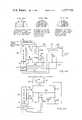
- FIG. 1is an electrical block diagram of the inventive power supply for a gas discharge lamp
- FIGS. 2A and 2Bare electrical schematic diagrams of alternative switching regulator circuits that can be used in the power supply of FIG. 1;
- FIGS. 3A, 3B and 3Care graphs illustrating the effect on power factor of various types of switching regulator circuits
- FIG. 4Ais an electrical schematic diagram of the inverter and resonant network components of the power supply of FIG. 1;
- FIG. 4Bis the same as 4A with a different inverter configuration.
- the inventive power supply 10is used to energize a gas discharge lamp 11 which may be of the mercury vapor, metal-halide, sodium or fluorescent type.
- ac power from a sourcesuch as the 60 Hz, 120 volt power lines, is connected via a pair of terminals 12a,12b to a bridge rectifier 13.
- the unfiltered output of the bridge rectifier 13is supplied via the lines 14 and 15 to a switching regulator 16. No filtering is used at the output of the bridge rectifier 13 to eliminate both (a) the lagging power factor and distortion which would result if an inductor were used to filter the rectified ac, and (b) the third harmonic distortion which would result if a capacitor were used.
- the switching regulator 13provides a substantially constant dc voltage to a pair of output lines 17, 18.
- afilter capacitor 19 connected across the output lines 17, 18has a value sufficiently large so as to filter at twice the ac line frequency (e.g., at 120 Hz).
- the duty cycle of the switching regulator 16is controlled in response to the output voltage across the capacitor 19, and therefor will depend on the average voltage level over several cycles of the rectified ac supplied to the input of the regulator 16.
- the regulated dc voltage on the lines 17, 18may be supplied to any load requiring direct current in FIG. 1 it is supplied to an inverter 20 which typically operates at a nominal frequency of 20 kHz.
- the output of the inverter 20is an ac voltage square wave having a nominal 20 kHz frequency.
- This ac voltageis fed to the lamp 11 via a resonant network 21which includes the lamp 11 as an element of a resonant circuit.
- a feedback path 22carries a control signal that adjusts the frequency of the inverter 20 to correspond to the resonant frequency of the network 21. In this manner, a resistive load is seen by the inverter 20 regardless of theoperating condition of the lamp 11, and sinusoidal voltage is provided to the lamp, resulting in improved lamp efficiency.
- the inverterswitches at the current null points of the network 21 output sinusoidal voltage, sincethe inverter 20 operates at the network 21 resonant frequency. Switching losses are reduced since the current through the inverter switching transistors is at or near zero when switching occurs. Therefor less expensive transistors of lower rating can be used.
- Dimming of the lamp 11can be accomplished by controlling the voltage supplied by the regulator 16 to the inverter 20. To this, an external adjustment 23 is provided to control the duty cycle and hence the voltage output of the switching regulator 16.
- the regulator 16 dutycyclemay be controlled by a photocell 24 positioned to sense the light level at a location illuminated by the lamp 11. In this way, if sunlight produces a high ambient light level at the location, this will be sensed by the photocell 24, resulting in dimming of the lamp 11. Energy is conserved while the desired illumination level is maintained.
- a current sensing resistor 25in series with oneof the lines 25, 26, to the lamp 11, as shown in FIG. 1.
- a feedback line 26is connected between the resistor 25 and the switching regulator 16 so as to control the output voltage cycle in response to the sensed output current to the lamp 11.
- FIG. 2Ashows one type of switching regulator 16A that can be used as the regulator 16 in the power supply 10.
- a switching transistor 30is turned on and off by an oscillator and drive circuit 31 at a rate (typically 30 kHz) that is above the audio range.
- a ratetypically 30 kHz
- the transistor 30is on, some energy is stored in an inductor 32 which maintains current during the off-time of the transistor 30 via a diode 33.
- a small RF filter capacitor 34prevents RF signals, which may be generated by the switching transientsof the transistor 30 from being conducted back to the ac line.
- the output voltageis a direct function of the input supply voltage time the duty cycle or on-to-off time ratio of the transistor 30. Since the output of the bridge rectifier 13 is unfiltered, the supply voltage to the switching regulator 16 varies between zero and the peak ac line voltage, at twice the input ac frequency. In a conventional switching regulator, the on-to-off time ratio normally is varied in response to the input supply voltage so that the on-time is greatest when the input voltage is least. As illustrated in FIG. 3A, this results in maximum current flow when the input voltage is minimum. This corresponds to a negative or very lagging power factor, and is undesirable.
- This effectcan be overcome by reversing the conventional approach and (a) making the on-time of the switching transistor 30 a maximum when the inputvoltage is greatest, and (b) using an inductor 32 that is sufficiently large so as to maintain substantially the same current through the switching transistor 30 regardless of the input voltage.
- the current waveformcan be matched to the voltage waveform, by controlling the on-time at each portion of the ac line half cycle as illustrated in FIG. 3B, thereby creating the effect of a resistive load orunity power factor.
- An alternative approachis (a) to make the inductor large with respect to the switching frequency (e.g., 30 kHz) but small with respect to the ac line frequency (e.g., 60 Hz), and (b) to hold the duty cycle (on-to-off time ratio) of the switching transistor 30 constant over a complete half-cycle of the input ac, but allowing it to vary only with gradual changes in the average input line voltage or required output voltage.
- the value of the output capacitor 19must be sufficient to filter the strong, twice line frequency (e.g., 120 Hz) ripple that will bepresent at the regulator output.
- the current waveformcan be made very closely to correspond to the input voltage waveform, as illustrated in FIG. 3C. The result is a unity power factor devoid of harmonic distortion.
- FIG. 2BA different form of switching regulator 16B, also usable as the regulator 16 in the power supply 10, is shown in FIG. 2B.
- the inductor 35ais the primary winding of a ferrite core transformer 35, and is connected in series with the switching transistor 36 across the input lines 14, 15 fromthe bridge rectifier 13. With this arrangement, the inductor 35a is loaded and unloaded each time the transistor 36 is turned on and off at the switching frequency. Output dc voltage is taken from the transformer secondary winding 35b via a diode 37.
- This circuitoffers the advantage that should the switching transistor 36 become shorted for any reason, input current will not flow to the load.
- the output voltagemay be regulated either by varying the switching frequency or the duty cycle.
- variable frequency controlthe oscillator and drive circuit 38advantageously includes a voltage controlled or like oscillator, the nominal frequency of which is controlled by the external adjustment 23, the photocell 24 or the feedbacksignal on the line 26.
- the capacitor 19should be sufficiently large so as to filter effectively at twice the ac line frequency. Changes in the filtered output voltage are used to vary the frequency of the oscillator and drive circuit 38 thereby to connect the switching frequencyso as to achieve substantially constant output voltage.
- FIG. 4ADetails of one format of the inverter 20 and the resonant network 21 are shown in FIG. 4A.
- the regulated dc voltagefrom the switching regulator 16is supplied alternately to one or the otherhalf windings 40a, 40b of an auto transformer 40 via a respective transistor 41 or 42.
- These two transistors 41, 42are alternately driven into conduction by an oscillator and drive circuit 43, one embodiment of which is shown in FIG. 5.
- the drive circuit 43switches one of the transistors 41, 42 completely off before turning the other one on. This insures that both transistors 41, 42 are never on at the same time.
- the ac voltage developed across the autotransformer 40 on the lines 44, 45is twice the dc input voltage. If the output of the regulator 16 is selected to be in the range of about 35 v dc to 50 v dc, the ac voltage developed across the lines 44, 45 will be on the order to 70 v to 100 v; thus, the use of the regulator suffering a lower voltage than line to the inverter allows the additional advantage of the use of inexpensive low voltage components.
- the resonant network 21includes the lamp 11 in series with an inductor 45 across a capacitor 46. Since the gas discharge lamp 11 is a negative impedance, which operates at relatively constant voltage, the inductor 45 serves in part to limit current flow through the lamp 11. Further, the inductor 45 and the lamp 11 together represent an inductive reactance in parallel with the capacitor 46. The value of the capacitor 46 is selected so that even when the lamp 11 appears as a short circuit (e.g., during thewarm-up of a high intensity discharge lamp) an inductive reactance is present, the combined reactance of the parallel circuit including the lamp11, the inductor 45 and the capacitor 46 will be capacitive. This capacitive reactance resonates with a series inductor 47.
- the frequency of the inverter 20is controlled such that the reactance of the inductor 47 equals the capacitive reactance of the series-parallel combination of the capacitor 46, the inductor 45 and the lamp 11.
- the network 21presents a resistive load to the inverter 20.
- a unity power factoris achieved.
- a sinusoidal voltageis presented to the lamp 11 and asinusoidal current load is seen by the inverter 20.
- the transistors 41, 42are switched full on and full of in "square-wave" fashion by the drive circuit 43, the current through the transistors 41, 42 is at a minimum when the switching occurs, as the sinusoidal signal across the resonant network 21 is going through null at this time.
- a phase detector 50compares the phase of the signal across the inductor 47, as sensed by a sense winding 47, with the phase of the signal across the transformer 40 as detected by a sense winding 40s.
- the phase of signalfrom winding 47smay also be compared with the phase of the drive signal totransistors 41 and 42 with the same result.
- the phase detector 50senses whether the actual phase difference is indeed 90 degrees, indicating that the inverter 20 is operating at the resonant frequency of the network 21. If not, an error signal is produced on a line 51 that causes the oscillator and drive circuit 43 to alter frequency until the resonant condition against is achieved.
- a voltage gainis achieved by the resonant network 21.
- the voltage developed across the capacitor 46, between the point 53 and the line 44,is related to the Q of the network 21 times the input voltage from the inverter 20.
- This developed voltageis normally selected to be onthe order of 700 v to 800 v ac, which is some three to four times greater than that required to sustain normal operation of a typical gas discharge lamp. Since the lamp and network 21 at resonance appear as a resistive load, and since the effective reactance of the network 21 components is high with respect to the lamp 11, substantially constant current will flowthrough the lamp 11, even though the voltage across the lamp will change under different operating conditions.
- inventive power supply 10ideal for driving both high intensity discharge (HID) and fluorescent lamps.
- HIDhigh intensity discharge
- Formetal halide, sodium and other HID lampsthe supply will provide proper drive for starting, during the warm-up period and for normal operation.
- fluorescent lampsproper drive and flickerless dimming is possible.
- Typical HID lampsrequire a starting voltage that is substantially higher than the operating voltage for the same lamp after it has heated up. Untilactually started, the impedance of an HID lamp is infinite, that is, it appears as an open circuit. In this start-up mode, the inductor 45 (FIG. 4) is effectively out of the circuit, and the resonant network 21 consistseffectively of the capacitor 46 in series with the inductor 47. Since theseare relatively lossless elements, the network 21 will exhibit a very high Q. The voltage developed across the capacitor 46, and hence across the capacitor 46, and hence across the lamp 11, will become very high, potentially reaching over a thousand volts. This high voltage will insure initiation of conduction of the lamp, regardless of the lamp's condition or age. In many cases, the supply 10 will start a lamp 11 that has deteriorated to a point where it cannot be started with a conventional ballast, the result is improved useful lifetime for the lamp.
- an HID lamptypically exhibits a very low impedance and thus presents virtually a short circuit load. In a conventional system this would place a very high current demand on the power supply.
- the inventive power supply 10however, the actual short circuit of the lamp 11is not seen as a shortened load. Rather, the "short circuit" effectively inserts the inductor 45 across the capacitor 46, thereby changing the resonant frequency of the network 21 but not shorting the supply.
- the feedback circuitwill shift the frequency of the inverter 20 to the new resonant frequency of the network 21, and the current limiting characteristic of this network will limit the current flow through the lamp 11 as it warms up.
- the inverter 20 frequencywill automatically beset somewhere between the extremes corresponding to the lamp start and lampwarm-up conditions at the new resonant frequency of the network 21. Diming to the HID lamp can be achieved either by changing the dc voltage suppliedto the inverter 20 by the switching regulator 16 or by altering the duty cycle of the inverter 20.
- the inventive power supply 10Among the benefits provided by the inventive power supply 10 are improved efficiency and the elimination of flicker in a metal arc lamp.
- the high frequency (typically 20 kHz) drive provided by the inverter 20tends to create a smaller diameter ion stream in a HID lamp then if the same lamp were driven at the ac line frequency.
- Increased efficiencyresults since concentration of the current into a smaller area creates a higher energy level in the gas molecules, thereby inducing more light output.
- a benefit of the inventive systemis that conventional, inexpensive components can be used.
- the transistors 41, 42need exhibit only a reasonable switching time, because of the modest switching frequency of about 20 kHz, and since the drive circuitry 43 provides for aquiescent time between turn-off of one transistor 41 or 42 and turn-on of the other.
- Use of a dc supply voltage from the regulator 16 of between 35 v dc and 50 v dcpermits use of transistors 41, 42 rated at about 100 volts.
- the use of a sinusoidal output signalalso reduces the performance requirements and hence the cost of the switching transistors 41 and 42.
- FIG. 4Bshows another inverter configuration that eliminates transformer 40and adds capacitors 57 and 58. Besides the advantages of simplicity and size this circuit puts even less voltage strain on transistors 41 and 42. Higher voltage from the regulator may be used when desired with transistors having the same voltage rating as shown in FIG. 4A. Also, voltage spikes associated with transformer drive are eliminated. Inductor 47 will increase in size somewhat however.
- An optional feature of the present inventionis that it facilitates batteryoperation of a gas discharge lamp, particularly during periods of power failure of the ac line source.
- a battery 70may be connected in series with a diode 71 across the output lines 17, 18 from the regulator 16, as shown in FIG. 1. During normal operation, the diode 71 effectively disconnects the battery 70 from the circuit. However, in the event of an ac power failure, the battery 70 will provide input voltage tothe inverter 20, maintaining the lamp 11 lit. If dimming is required, the voltage of the battery 70 must be equal to the lowest desired output of the regulator 16. In such instance, the lamp light output will be dimmed under battery operation, but will be remain illuminated, e.g., for emergency evacuation purposes. The lower battery voltage will result in longer operation.
- a charging circuit 72may be provided to charge the battery 72 from the dc voltage present at the regulator 16 output during periods of normal operation.
- HID lampUse of the standby battery 70 is particularly valuable with the HID lamps. If an HID lamp is extinguished, it must first be cooled before it can be relit. With standby battery operation, the HID lamp will not be extinguished during short power outages, and therefore will come back on immediately to the set intensity when the power is restored.
- the inventive circuitprovides for dimming the lamps.
- the input dc voltage from the switching regulatorcan be varied.
- This dc voltage levelcan be adjusted manually using the external adjustment 23 or in response to some other condition, as for example the ambient light level sensed by the photocell 24. Dimming is effectuated since the voltage developed across the capacitor 46 (FIG. 4) is a direct multiple of the voltage supplied to the network 21 which itself is twice the dc input voltage from the regulator 16.
- the voltage across the capacitor 46will be altered accordingly. Since the inductor 45 is the principal sourceof impedance in the series connection of the inductor 45 and the lamp 11, the current through the lamp will be related almost directly to the voltage across the capacitor 46. Thus a change in input voltage will causethe lamp 11 current to drop proportionately. The lamp will remain lit at a changed intensity. The high voltage available across the capacitor 46 willkeep the lamp 11 lit even at lower intensity levels, despite the negative resistance characteristics of the lamp, thereby insuring flickerless dimming performance.
Landscapes
- Engineering & Computer Science (AREA)
- Power Engineering (AREA)
- Business, Economics & Management (AREA)
- Emergency Management (AREA)
- Circuit Arrangements For Discharge Lamps (AREA)
- Inverter Devices (AREA)
Abstract
Description
1. Field of the Invention
The present invention relates to a power supply for a gas discharge lamp, and particularly to such a device employing a switching regulator reflecting a unity power factor and no third harmonic distortion to the ac line, an inverter and a resonant network including the lamp load, the inverter operating at the resonant frequency of the network to provide a sinusoidal output voltage.
2. Description of the Prior Art
Various types of gas discharge lamps are widely used for lighting purposes. These include fluorescent lamps, high intensity discharge lamps of different types including the metal halide varieties and sodium lamps of both high and low pressure. A common feature of all these lamps is that they require some type of ballast for operation. Ordinarily ballast transformers are used. This approach has several shortcomings. For operation at line frequency, the ballast must be of substantial physical size and weight, resulting from the large magnetic transformers and capacitors that are required. Efficiency is low. The ballast must be operated at the rated line voltage, and any serious deviation can cause either the ballast to overheat or the lamp to flicker. Dimming of the lamp is difficult or impossible.
One approach of the prior art to overcome these difficulties has been the use of switching regulators to provide to the lamp a direct current that is switched on and off at a high frequency. While dc will light the lamp adequately, a specially designed lamp is required if the lamp lifetime is not to be sacrificed considerably. Moreover, such circuits require that the ac line voltage first be rectified and filtered for input to the regulator.
If inductive filtering is used, a very poor power factor will result, and the inductor may have to be the same large size as the original ballast. Also, line distortion is created by the combination of the inductor and the bridge rectifier. If capacitive filtering is used, all of the current will be conducted during the peak of the ac line cycle. This produces "third harmonic distortion" which heats up the pole transformers and requires extra heavy wiring between the device and the power source.
Another approach of the prior art is shown in the U.S. Pat. No. 3,999,100. This supply uses a switching regulator in conjunction with a commutator to provide power to a metal halide lamp. The commutator is operated at or near the ac line frequency.
The principle object of the present invention is to provide an improved electronic ballast for a gas discharge lamp. Other objectives are to provide such a lamp power supply wherein:
(a) no third harmonic distortion is produced and the supply has a near unity power factor;
(b) improved efficiency results from supplying the lamp with high frequency ac power;
(c) dimming is facilitated for both fluorescent and high intensity gas discharge lamps;
(d) the ballast will operate properly despite line voltage variation;
(e) all components are lightweight, small in size and inexpensive;
(f) sufficiently high output voltage is provided to start high intensity gas discharge lamps;
(g) circuitry automatically compensates for changing lamp performance characteristics, including during the warm-up period of high intensity lamps;
(h) sinusoidal output voltage is produced, with concomitant benefits in efficiency, less stringent performance requirements and hence lower cost for the circuit switching transistors, and substantial elimination of radio frequency interference;
(i) dimming may be accomplished in response to ambient light conditions; and
(j) provision is made for battery operation in the event of ac power line failure.
Yet another object of the invention is to provide the benefits of (a) (d) (e) for other than ballast applications.
These and other objectives are achieved in accordance with the present invention by providing a power supply for a gas discharge lamp wherein a switching regulator is used to drive an inverter, the output of which is supplied to the lamp via a resonant network that includes the lamp. A feedback circuit maintains the inverter switching rate at the resonant frequency of the network, so that a sinusoidal output is produced.
The switching regulator is driven by unfiltered rectified ac line power. The regulator utilizes an output filter capacitor which is effective at twice the ac line frequency. The switching duty cycle or rate is responsive to the regulator output voltage averaged over several half cycles of the ac line frequency. In this way, a unity power factor is achieved without third harmonic distortion.
The resonant network includes a capacitor shunted by an inductor in series with the lamp load. Component values are selected so that these circuit elements together exhibit capacitive reactance under all lamp impedance conditions. Another inductor is connected in series with these circuit elements to form a series resonant circuit across the inverter output. A phase detector or other circuit controls the inverter switching rate so that it equals the resonant frequency of the network. The circuit will work equally well with capacitors replacing the inductors and an inductor in place of the capacitor if high harmonies of the inverter frequence can be tolerated or desired in the load.
Dimming is accomplished either by varying the duty cycle of the inverter or by altering the dc voltage level provided to the inverter from the switching regulator.
The features of the present invention which are believed to be novel are set forth with particularity in the appended claims. The present invention, both as to its organization and manner of operation, together with further objects and advantages thereof, may best be understood by reference to the following description, taken in connection with the accompanying drawings in which:
FIG. 1 is an electrical block diagram of the inventive power supply for a gas discharge lamp;
FIGS. 2A and 2B are electrical schematic diagrams of alternative switching regulator circuits that can be used in the power supply of FIG. 1;
FIGS. 3A, 3B and 3C are graphs illustrating the effect on power factor of various types of switching regulator circuits;
FIG. 4A is an electrical schematic diagram of the inverter and resonant network components of the power supply of FIG. 1;
FIG. 4B is the same as 4A with a different inverter configuration.
The following detailed description is of the best presently contemplated modes of carrying out the invention. This description is not to be taken in a limiting sense, but is made merely for the purpose of illustrating the general principles of the invention since the scope of the invention best is defined by the appended claims.
Operation characteristics attributed to forms of the invention first described also shall be attributed to forms later described, unless such characteristics obviously are unapplicable or unless specific exception ismade.
Referring to FIG. 1, the inventive power supply 10 is used to energize agas discharge lamp 11 which may be of the mercury vapor, metal-halide, sodium or fluorescent type. To this end, ac power from a source such as the 60 Hz, 120 volt power lines, is connected via a pair ofterminals 12a,12b to abridge rectifier 13.
The unfiltered output of thebridge rectifier 13 is supplied via thelines switching regulator 16. No filtering is used at the output of thebridge rectifier 13 to eliminate both (a) the lagging power factor and distortion which would result if an inductor were used to filter the rectified ac, and (b) the third harmonic distortion which would result if a capacitor were used.
The switchingregulator 13 provides a substantially constant dc voltage to a pair ofoutput lines afilter capacitor 19 connected across theoutput lines regulator 16 is controlled in response to the output voltage across thecapacitor 19, and therefor will depend on the average voltage level over several cycles of the rectified ac supplied to the input of theregulator 16.
This is in contradistinction to the typical prior art arrangement in which the switching regulator duty cycle is responsive to changes in the input line voltage and in which a small output filter capacitor is used. Such a capacitor filters effectively at the regulator switching frequency (typically 20 kHz) but not at twice the line frequency (e.g., at 120 Hz). Therefor such a prior art regulator draws more current from the ac line during the low voltage portions of the ac cycle and less current during the high voltage portions. Such regulation produces a lagging power factorsimilar to that produced by inductive input filtering, and hence is undesirable. As noted above, this is eliminated by the inventive arrangement in which theoutput filter capacitor 19 is sufficiently large so as to filter over several cycles of the supplied rectified ac voltage.
The regulated dc voltage on thelines inverter 20 which typically operates at a nominal frequency of 20 kHz. Thus the output of theinverter 20 is an ac voltage square wave having a nominal 20 kHz frequency. This ac voltage is fed to thelamp 11 via a resonant network 21which includes thelamp 11 as an element of a resonant circuit. A feedback path 22 carries a control signal that adjusts the frequency of theinverter 20 to correspond to the resonant frequency of thenetwork 21. In this manner, a resistive load is seen by theinverter 20 regardless of theoperating condition of thelamp 11, and sinusoidal voltage is provided to the lamp, resulting in improved lamp efficiency. The inverter switches at the current null points of thenetwork 21 output sinusoidal voltage,sincethe inverter 20 operates at thenetwork 21 resonant frequency. Switching losses are reduced since the current through the inverter switching transistors is at or near zero when switching occurs. Therefor less expensive transistors of lower rating can be used.
Dimming of thelamp 11 can be accomplished by controlling the voltage supplied by theregulator 16 to theinverter 20. To this, anexternal adjustment 23 is provided to control the duty cycle and hence the voltage output of the switchingregulator 16. Alternatively, theregulator 16 dutycycle may be controlled by aphotocell 24 positioned to sense the light level at a location illuminated by thelamp 11. In this way, if sunlight produces a high ambient light level at the location, this will be sensed by thephotocell 24, resulting in dimming of thelamp 11. Energy is conserved while the desired illumination level is maintained.
In some applications it may be desirable to control the output to thelamp 11 in response to the current flowing to the lamp. This can be accomplished by providing acurrent sensing resistor 25 in series with oneof thelines lamp 11, as shown in FIG. 1. A feedback line 26is connected between theresistor 25 and the switchingregulator 16 so as to control the output voltage cycle in response to the sensed output current to thelamp 11.
FIG. 2A shows one type ofswitching regulator 16A that can be used as theregulator 16 in the power supply 10. A switchingtransistor 30 is turned on and off by an oscillator and drivecircuit 31 at a rate (typically 30 kHz) that is above the audio range. When thetransistor 30 is on, some energy is stored in aninductor 32 which maintains current during the off-time of thetransistor 30 via adiode 33. A smallRF filter capacitor 34 prevents RF signals, which may be generated by the switching transientsof thetransistor 30 from being conducted back to the ac line.
In such aregulator 16A, the output voltage is a direct function of the input supply voltage time the duty cycle or on-to-off time ratio of thetransistor 30. Since the output of thebridge rectifier 13 is unfiltered, the supply voltage to the switchingregulator 16 varies between zero and the peak ac line voltage, at twice the input ac frequency. In a conventional switching regulator, the on-to-off time ratio normally is varied in response to the input supply voltage so that the on-time is greatest when the input voltage is least. As illustrated in FIG. 3A, this results in maximum current flow when the input voltage is minimum. This corresponds to a negative or very lagging power factor, and is undesirable.
This effect can be overcome by reversing the conventional approach and (a) making the on-time of the switching transistor 30 a maximum when the inputvoltage is greatest, and (b) using aninductor 32 that is sufficiently large so as to maintain substantially the same current through the switchingtransistor 30 regardless of the input voltage. With this arrangement, the current waveform can be matched to the voltage waveform, by controlling the on-time at each portion of the ac line half cycle as illustrated in FIG. 3B, thereby creating the effect of a resistive load orunity power factor.
An alternative approach is (a) to make the inductor large with respect to the switching frequency (e.g., 30 kHz) but small with respect to the ac line frequency (e.g., 60 Hz), and (b) to hold the duty cycle (on-to-off time ratio) of the switchingtransistor 30 constant over a complete half-cycle of the input ac, but allowing it to vary only with gradual changes in the average input line voltage or required output voltage. In this case, the value of theoutput capacitor 19 must be sufficient to filter the strong, twice line frequency (e.g., 120 Hz) ripple that will bepresent at the regulator output. With this arrangement, the current waveform can be made very closely to correspond to the input voltage waveform, as illustrated in FIG. 3C. The result is a unity power factor devoid of harmonic distortion.
A different form of switchingregulator 16B, also usable as theregulator 16 in the power supply 10, is shown in FIG. 2B. Here theinductor 35a is the primary winding of aferrite core transformer 35, and is connected in series with the switchingtransistor 36 across the input lines 14, 15 fromthebridge rectifier 13. With this arrangement, theinductor 35a is loaded and unloaded each time thetransistor 36 is turned on and off at the switching frequency. Output dc voltage is taken from the transformer secondary winding 35b via adiode 37. This circuit offers the advantage that should the switchingtransistor 36 become shorted for any reason, input current will not flow to the load.
In thecircuit 16B, the output voltage may be regulated either by varying the switching frequency or the duty cycle. With variable frequency controlthe oscillator and drivecircuit 38 advantageously includes a voltage controlled or like oscillator, the nominal frequency of which is controlled by theexternal adjustment 23, thephotocell 24 or the feedbacksignal on theline 26. Here again, thecapacitor 19 should be sufficiently large so as to filter effectively at twice the ac line frequency. Changes in the filtered output voltage are used to vary the frequency of the oscillator and drivecircuit 38 thereby to connect the switching frequencyso as to achieve substantially constant output voltage.
Other forms of switching regulator circuits may also employ the novel concepts claimed herein of tayloring the duty cycle to provide unity powerfactor without line distortion. Details of one format of theinverter 20 and theresonant network 21 are shown in FIG. 4A. The regulated dc voltagefrom the switchingregulator 16 is supplied alternately to one or theotherhalf windings auto transformer 40 via arespective transistor transistors circuit 43, one embodiment of which is shown in FIG. 5. Advantageously, thedrive circuit 43 switches one of thetransistors transistors transistors autotransformer 40 on thelines regulator 16 is selected to be in the range of about 35 v dc to 50 v dc, the ac voltage developed across thelines
Theresonant network 21 includes thelamp 11 in series with aninductor 45 across acapacitor 46. Since thegas discharge lamp 11 is a negative impedance, which operates at relatively constant voltage, theinductor 45 serves in part to limit current flow through thelamp 11. Further, theinductor 45 and thelamp 11 together represent an inductive reactance in parallel with thecapacitor 46. The value of thecapacitor 46 is selected so that even when thelamp 11 appears as a short circuit (e.g., during thewarm-up of a high intensity discharge lamp) an inductive reactance is present, the combined reactance of the parallel circuit including the lamp11, theinductor 45 and thecapacitor 46 will be capacitive. This capacitive reactance resonates with aseries inductor 47.
The frequency of theinverter 20 is controlled such that the reactance of theinductor 47 equals the capacitive reactance of the series-parallel combination of thecapacitor 46, theinductor 45 and thelamp 11. Under such resonant condition, thenetwork 21 presents a resistive load to theinverter 20. A unity power factor is achieved. Moreover, under such resonant condition, a sinusoidal voltage is presented to thelamp 11 and asinusoidal current load is seen by theinverter 20. Thus, even though thetransistors drive circuit 43, the current through thetransistors resonant network 21 is going through null at this time.
Under various operating conditions of thelamp 11, the effective impedance of thelamp 11, and hence the resonant frequency of thenetwork 21 will change. A feedback circuit is used to correct the frequency of theinvertor 20 so as to maintain the inverter frequency in resonance withthenetwork 21 when such lamp impedance changes occur. To this end, a phase detector 50 (FIG. 4) compares the phase of the signal across theinductor 47, as sensed by a sense winding 47, with the phase of the signal across thetransformer 40 as detected by a sense winding 40s. The phase of signalfrom winding 47s may also be compared with the phase of thedrive signal totransistors
Since in an inductor the current through it is 90 degress out of phase withthe voltage across it and since the current ininductor 45 is equal to thatflowing in the load the voltage on the sense winding 45s oninductor 45 will be 90 degrees out of phase with the current in the load therefore with the voltage across the load since the load is not reactive. At the proper frequency for resonance of the network the voltage input to the network must be in phase with the voltage across the load for the network to appear resistive to the inverter. Thephase detector 50 senses whether the actual phase difference is indeed 90 degrees, indicating that theinverter 20 is operating at the resonant frequency of thenetwork 21. If not, an error signal is produced on aline 51 that causes the oscillator and drivecircuit 43 to alter frequency until the resonant condition against is achieved.
At resonance, a voltage gain is achieved by theresonant network 21. The voltage developed across thecapacitor 46, between thepoint 53 and theline 44, is related to the Q of thenetwork 21 times the input voltage from theinverter 20. This developed voltage is normally selected to be onthe order of 700 v to 800 v ac, which is some three to four times greater than that required to sustain normal operation of a typical gas discharge lamp. Since the lamp andnetwork 21 at resonance appear as a resistive load, and since the effective reactance of thenetwork 21 components is high with respect to thelamp 11, substantially constant current will flowthrough thelamp 11, even though the voltage across the lamp will change under different operating conditions.
These operating characteristics make the inventive power supply 10 ideal for driving both high intensity discharge (HID) and fluorescent lamps. Formetal halide, sodium and other HID lamps, the supply will provide proper drive for starting, during the warm-up period and for normal operation. For fluorescent lamps, proper drive and flickerless dimming is possible.
Typical HID lamps require a starting voltage that is substantially higher than the operating voltage for the same lamp after it has heated up. Untilactually started, the impedance of an HID lamp is infinite, that is, it appears as an open circuit. In this start-up mode, the inductor 45 (FIG. 4) is effectively out of the circuit, and theresonant network 21 consistseffectively of thecapacitor 46 in series with theinductor 47. Since theseare relatively lossless elements, thenetwork 21 will exhibit a very high Q. The voltage developed across thecapacitor 46, and hence across thecapacitor 46, and hence across thelamp 11, will become very high, potentially reaching over a thousand volts. This high voltage will insure initiation of conduction of the lamp, regardless of the lamp's condition or age. In many cases, the supply 10 will start alamp 11 that has deteriorated to a point where it cannot be started with a conventional ballast, the result is improved useful lifetime for the lamp.
With no load current flowing there is no voltage drop acrossinductor 45 thus no feedback on sense winding 45s therefore for open load conditions voltage is sensed at thejunction 53 ofcapacitor 46 andinductor 47 and supplied to phasedetector 50 byline 55. Under such open load conditions the voltage will continue to rise atpoint 50 as long as the regulator will supply the necessary current to the inverter. Therefore, current to the inverter is sensed by the voltage acrossresistor 56 and fed back to theregulator 16 online 26 to control the input to the inverter and therefore the maximum voltage permissable atpoint 53.
During warm-up, an HID lamp typically exhibits a very low impedance and thus presents virtually a short circuit load. In a conventional system this would place a very high current demand on the power supply. In the inventive power supply 10 however, the actual short circuit of the lamp 11is not seen as a shortened load. Rather, the "short circuit" effectively inserts theinductor 45 across thecapacitor 46, thereby changing the resonant frequency of thenetwork 21 but not shorting the supply. The feedback circuit will shift the frequency of theinverter 20 to the new resonant frequency of thenetwork 21, and the current limiting characteristic of this network will limit the current flow through thelamp 11 as it warms up. Subsequent to warm-up, when normal lamp operation is achieved and the lamp impedance is finite but not short-circuited, proper voltage with substantially constant current will continue to be provided by thesupply 11. Theinverter 20 frequency will automatically beset somewhere between the extremes corresponding to the lamp start and lampwarm-up conditions at the new resonant frequency of thenetwork 21. Diming to the HID lamp can be achieved either by changing the dc voltage suppliedto theinverter 20 by the switchingregulator 16 or by altering the duty cycle of theinverter 20.
Among the benefits provided by the inventive power supply 10 are improved efficiency and the elimination of flicker in a metal arc lamp. The high frequency (typically 20 kHz) drive provided by theinverter 20 tends to create a smaller diameter ion stream in a HID lamp then if the same lamp were driven at the ac line frequency. Increased efficiency results since concentration of the current into a smaller area creates a higher energy level in the gas molecules, thereby inducing more light output.
In prior art high frequency drive sources, flicker was produced in the metal arc lamp. Since the lamp tube diameter provided for a larger ion stream than that which is present with high frequency drive, the smaller diameter ion stream is free to wander or move about in the unconfined areawithin the tube. This moving is referred to as "flicker". It sometimes appears as slowly moving or rotating standing waves in the ion stream.
It has been found that flicker is eliminated by the frequency control employed in the inventive power supply 10. The movement of the ion stream is accompanied by a slight change in lamp impedance. As discussed above, this results in a concomitant change in the resonant frequency of thenetwork 21 and hence in a corrective change in the frequency of theinverter 20. This change in drive frequency has been found to eliminate flicker.
A benefit of the inventive system is that conventional, inexpensive components can be used. In theinverter 20, thetransistors drive circuitry 43 provides for aquiescent time between turn-off of onetransistor regulator 16 of between 35 v dc and 50 v dc permits use oftransistors transistors
FIG. 4B shows another inverter configuration that eliminates transformer 40and addscapacitors transistors Inductor 47 will increase in size somewhat however.
An optional feature of the present invention is that it facilitates batteryoperation of a gas discharge lamp, particularly during periods of power failure of the ac line source. To this end, a battery 70 may be connected in series with a diode 71 across theoutput lines regulator 16, as shown in FIG. 1. During normal operation, the diode 71 effectively disconnects the battery 70 from the circuit. However, in the event of an ac power failure, the battery 70 will provide inputvoltage tothe inverter 20, maintaining thelamp 11 lit. If dimming is required, the voltage of the battery 70 must be equal to the lowest desired output of theregulator 16. In such instance, the lamp light output will be dimmed under battery operation, but will be remain illuminated, e.g., for emergency evacuation purposes. The lower battery voltage will result in longer operation. A chargingcircuit 72 may be provided to charge thebattery 72 from the dc voltage present at theregulator 16 output during periods of normal operation.
Use of the standby battery 70 is particularly valuable with the HID lamps. If an HID lamp is extinguished, it must first be cooled before it can be relit. With standby battery operation, the HID lamp will not be extinguished during short power outages, and therefore will come back on immediately to the set intensity when the power is restored.
As noted, the inventive circuit provides for dimming the lamps. To accomplish this, the input dc voltage from the switching regulator can be varied. This dc voltage level can be adjusted manually using theexternal adjustment 23 or in response to some other condition, as for example the ambient light level sensed by thephotocell 24. Dimming is effectuated since the voltage developed across the capacitor 46 (FIG. 4) is a direct multiple of the voltage supplied to thenetwork 21 which itself is twice the dc input voltage from theregulator 16.
By altering theregulator 16 output, the voltage across thecapacitor 46 will be altered accordingly. Since theinductor 45 is the principal sourceof impedance in the series connection of theinductor 45 and thelamp 11, the current through the lamp will be related almost directly to the voltage across thecapacitor 46. Thus a change in input voltage will causethelamp 11 current to drop proportionately. The lamp will remain lit at a changed intensity. The high voltage available across thecapacitor 46 willkeep thelamp 11 lit even at lower intensity levels, despite the negative resistance characteristics of the lamp, thereby insuring flickerless dimming performance.
Intending to claim all novel features shown and described, the inventor:
Claims (33)
1. A power supply for a gas discharge lamp comprising:
a source of DC voltage;
an inverter connected to receive DC voltage from said source comprising a pair of switching transistors for alternately switching DC voltage from said source;
a resonant network whereby the output of the inverter as presented to the lamp will be sinusoidal in wave shape;
said inverter includes a transformer, the output of said transformer being connected to said resonant network which is in turn connected to the lamp;
an oscillator connected to control the switching rate of said pair of switching transitors to switch said transistors at such time as the current flowing in or out of said resonant circuit shall be at or near zero;
a feed-back means which determines that said resonant network is at resonance and that it presents a resistive load to said inverter;
a frequency control means for said oscillator connected to the feedback means in such a manner as to control the frequency to maintain resonance in said resonant network.
2. A power supply according to claim 1 wherein said
feedback means comprises;
a first sense winding on said transformer of said inverter;
a second sense winding on a reactor of said network;
a phase detector connected to receive the said signals from said first and second sense windings and to provide an output indicative of the phase relationship there between; and
means for controlling the frequency of said oscillator and, hence, the switching rate of said inverter in response to the phase indicative output signal from said phase detector.
3. A power supply according to claim 1 wherein said
feedback means comprises;
a phase detector connected to receive signals from first, the output of said oscillator driving the switching transistors, and, second, the voltage present within the network; and
means for controlling the frequency of said oscillator and, hence, the switching rate of said inverter in response to the appropriate phase relationship required to maintain a purely resistive load on said inverter output.
4. A power supply for a gas discharge lamp comprising:
a source of DC voltage;
an inverter connected to receive DC from said source comprising a pair of switching transistors;
a resonant network including said lamp wherein said network is connected to the output of said inverter;
feedback means operably connected to said resonant network and to said inverter for controlling the switching rate of said inverter so that it is maintained at the resonant frequency of said resonant network by commutating the voltage applied to said resonant network at such times as the current flowing in or out of said resonant circuit shall be at or near zero;
said inverter comprises;
an autotransformer, having an output connected to said resonant network;
first and second switching transistors connected to supply DC voltage from said source to said autotransformer in respective first and opposite polarity; and
oscillator and drive circuitry connected to said switching transistors for alternately turning one transistor on and the other transistor off, said circuitry providing a delay after each transistor is turned off before the other is turned on; and
said feedback means controls the frequency of said oscillator and drive circuitry via phase detection.
5. A power supply according to claim 4 wherein it further consists:
duty cycle control means cooperating with said oscillator and drive circuiting, for symmetrically adjusting the relative on and off times of said first and second switching transistors.
6. A power supply for a gas discharge lamp comprising:
a source of DC voltage;
an inverter connected to receive DC voltage from said source;
a resonant network including said lamp wherein said network is connected to the output of said inverter;
feedback means operably connected to said resonant network and to said inverter for controlling the switching rate of said inverter so that it is maintained at the resonant frequency of said resonant network by commutating the voltage applied to said inverter at such times as the current to and from said resonant network is at or near zero;
said resonant network comprising:
a reactor;
a second reactor of opposite polarity of said first reactor connected in series with said lamp across said first reactor, the values of said first and second reactors being selected so that said lamp, said second reactor and said first reactor together exhibit a reactance of the sign of said first reactor, and
a third reactor of opposite reactance sign connected in series with said previously described first reactor, second reactor and lamp combination so as to form a series resonant circuit.
7. A direct current power supply, comprising:
a source of DC voltage which includes rectification means for converting AC line power to pulsating DC;
a switching regulator;
connection means allowing the essentially unfiltered pulsating DC to be the source for said switching regulator;
said switching regulator made deliberately nonresponsive to the frequency of the pulsating DC supplied by said rectification means so as not to compensate for the variation of input voltage at the pulsating frequency;
said switching regulator output is filtered by a large capacitor to make up for the regulator's nonresponsiveness to the variation in input voltage to said switching regulator caused by said pulsating DC;
wherein said nonresponsiveness is accomplished by maintaining the on to off time ratio of the said switching regulator essentially constant over the full AC half cycle with any such ratio changes occurring over the average input voltage such that changes will not appreciably affect said ratio during any one half cycle of AC line power.
8. A power supply according to claim 7 wherein said switching regulator comprises;
a switching transistor connected in series with a storage inductor in series with a still further output filter capacitor, the output being taken from across said capacitor;
a diode connected across the series combination of said storage inductor and said output capacitor; and,
drive circuitry for said switching transistor deliberately made nonresponsive to changes in the input voltage at the pulsating DC frequency that are reflected at the output.
9. A power supply according to claim 7 wherein a small capacitor is inserred across the output of the rectifier means and thus the input of said switching regulator, said capacitor having an impedance high enough not to cause any filtering affects at the low line frequency but low enough to adequately filter the high frequency of the inverter;
said capacitor averaging the high frequency switching pulses and thus producing in conjunction with the constant on to off ratio of the switching transistor a current wave form essentially in phase with the line voltage input.
10. A power supply according to claim 7 wherein said switching regulator comprises;
a storage inductor type transformer;
a primary winding of said transformer connected in series with a switching transistor;
a secondary winding of said transformer polarized to discharge when said switching transistor is in the nonconductive mode by means of a diode connecting in series with said secondary winding;
a drive for said switching transistor made deliberately nonresponsive to the pulsating DC supplied by said rectification means; and
an output filter capacitor made large to make up for the regulators nonresponsiveness to the pulsating DC supply.
11. A power supply according to claim 10 wherein a small filter capacitor is connected across the input of said switching regulator to filter the high frequency only.
12. A power supply according to claim 7 wherein said switching regulator comprises;
a switching transistor connected in series with a storage inductor large enough to maintain near constant current during the line frequency time of one half cycle in series with an output filter capacitor, the output being taken from across said capacitor;
a diode connected across said storage inductor and output capacitor series combination; drive circuitry for said switching transistor deliberately made inversely responsive to the line frequency voltage changes to produce an average current equal in wave form to that of the line input voltage; and,
a small filter capacitor connected across the input to said switching regulator to filter the high frequency only.
13. A gas discharge lamp ballast comprising:
a source of direct current and voltage;
an inverter which generates a square wave output;
a resonant network placed between the inverter and the gas discharge lamp, said resonant network constructed to draw current in a sinusoidal manner from said inverter; and
a feedback means to control the frequency of said inverter such that the lamp will always effectively appear as a resistive load to said inverter in that the sinusoidal current drawn from said resonant network and lamp combination will be in phase with the square wave output of said inverter such that the said voltage and said current will pass through zero at or near the same time regardless of wide variations in lamp impedance.
14. A gas discharge lamp ballast according to claim 13 wherein said inverter comprises switching elements and wherein said resonant network is constructed such as to demand current from the inverter in a sinusoidal manner in order that when said inverter is operating at the resonant frequency of said resonant network the switching elements of said inverter are switched only at that time that the time derivative of current flowing through them is at or near maximum.
15. A gas discharge lamp ballast according to claim 13 wherein said feedback comprises;
a phase detector connected to receive signals from first, the output of said oscillator driving the switching transistor, and, second, the voltage present within said resonant network; and,
means for controlling the frequency of said oscillator and, hence, the switching rate of said inverter in response to the appropriate phase relationship required to maintain a purely resistive load on said inverter output.
16. A gas discharge lamp ballast according to claim 13 wherein said resonant network comprises;
a first reactor;
a second reactor of opposite polarity of said first reactor connected in series with said lamp across said first reactor, the values of said first and second reactors being selected so that said lamp and said second reactor and said first reactor in the described configuration exhibit a reactance of the sign of said first reactor; and,
a third reactor connected in series with said previously described combination of said first reactor, second reactor, and lamp, so as to form a series resonant circuit.
17. A gas discharge lamp ballast according to claim 16 wherein the performance of said lamp and said first, second and third reactor combination is fed back to the inverter driver such that said inverter operates always at the resonant frequency of said reactor combination regardless of changes caused by variation in said lamp characteristics.
18. A gas discharge lamp ballast according to claim 13 wherein said inverter includes;
a transformer, the output of said transformer being connected to a resonant network which is in turn connected to said gas discharge lamp;
a pair of switching transistors for alternately switching DC voltage from said source of the input of said transformer;
an oscillator connected to control the switching rate of said pair of switching transistors;
a feedback means which determines that the resonant network is at resonance and that it presents a resistive load to said inverter transformer output; and,
a frequency control means for said oscillator connected to said feedback means in such a manner as to control the frequency to maintain the network at resonance.
19. A gas discharge lamp ballast according to claim 18 wherein said feedback means comprises;
a first sense winding of said transformer of said inverter;
a second sense winding on a reactor of said network;
a phase detector connected to receive the said signals from said first and second sense windings and to provide an output indicative of the phase relationship therebetween; and,
means for controlling the frequency of said oscillator and, hence, the switching rate of said inverter in response to the phase indicative output signal from said phase detector.
20. A gas discharge lamp ballast according to claim 18 wherein said feedback means comprises;
a phase detector connected to receive signals from first, the output of said oscillator driving said switching transistors, and, second, the voltage present within said network; and,
means for controlling the frequency of said oscillator and, hence, the switching rate of said inverter in response to the appropriate phase relationship between said first and second signals required to maintain a purely resistive load on said inverter output.
21. A gas discharge lamp ballast according to claim 13 wherein said inverter comprises;
a first switching transistor connected between said direct current and voltage source and said resonant network;
a second switching transistor connected between the input to said resonant network at the same point as said first switching transistor and the common of said direct current and voltage source;
an oscillator and drive circuit to alternately switch said first and second switching transistor and to control the switching rate;
a feedback means which determines that said resonant network is at resonance and that it presents a resistive load to the two switching transistors; and,
a frequency control means for said oscillator connected to said feedback means in such a manner as to control the frequency to maintain said network at resonance.
22. A gas discharge lamp ballast according to claim 21 wherein the common side of said resonant network and lamp combination is the mid-point of two capacitors connected in series between said direct current and voltage source and the common of said source.
23. A gas discharge lamp ballast according to claim 21 wherein said feedback means comprises;
a first sense means of the drive to said switching transistors;
a second sense means consisting of a winding on a reactor of said network; and
a phase detector means connected to receive the said feedback from said first and second sense means and to provide an output indicative of the phase relationship therebetween.
24. A gas discharge lamp ballast according to claim 23 wherein said second sense means consists of a voltage present within the resonant network.
25. A gas discharge lamp ballast according to claim 13 wherein said direct current and voltage source comprises;
a source of DC voltage which includes rectification means for converting AC line power to pulsating DC;
a switching regulator;
connection means to allow the essentially unfiltered pulsating DC to become the source for said switching regulator, said switching regulator made deliberately nonresponsive to the frequency of said pulsating DC supplied by said rectification means so as not to compensate for the variation of input voltage at the pulsating DC frequency as reflected on the output of said switching regulator.
26. A gas discharge lamp ballast according to claim 25 wherein an external adjustment may be made in the on to off time ratio of the switching regulator in response to the illumination effect produced by said gas discharge lamp through the use of a photocell.
27. A gas discharge lamp ballast according to claim 25 whereby the said on to off time ratio of said switching regulator may be adjusted in response to a feedback means indicative of the current in said gas discharge lamp such that the voltage to said inverter will be that required to maintain a setable lamp current.
28. A gas discharge lamp ballast according to claim 13 wherein said source of direct current and voltage is comprised of a battery.
29. A gas discharge lamp ballast according to claim 28 wherein said source of direct current and voltage also comprises a switching regulator connected in such a manner as to supply power as long as line voltage is available, and allowing for said battery to commence supplying voltage to said inverter in the event of line power failure.
30. A gas discharge lamp ballast according to claim 29 wherein a charge means is provided from the said source of direct current and voltage to maintain the battery in a fully charged condition while the power line is supplying said source of direct current and voltage.
31. A power supply for a gas discharge lamp comprising;
a source of DC voltage;
a resonant network comprising: a reactor;
a second reactor of opposite polarity of said first reactor connected in series with said lamp across said first reactor, the values of said first and second reactors being selected so that said lamp, said second reactor and said first reactor together exhibit a reactance of the sign of said first reactor; and
a third reactor connected in series with said first reactor so as to form a series resonant circuit with the reactance of said first reactor, said second reactor and said lamp;
an inverter connected to receive DC voltage from said source comprising:
a pair of switching transistors for alternately switching DC voltage from said source to the input of said resonant network; and
an oscillator connected to control the switching rate of said pair of switching transistors;
feedback means comprising:
first sense means in said inverter;
second sense means in said network; and
a phase detector connected to receive the signals from said first and second sense means and to provide an output signal indicator of the phase relationship therebetween; and
means for controlling the frequency of said oscillator, and hence, the switching rate of said inverter, in response to the phase-indicative output signal from said phase detector such that the switching rate of said inverter is maintained at the frequency of said resonant network by commutating the voltage applied to said resonant network at such times as the rate-of-change of current flow in said resonant circuit is at or near maximum.
32. A power supply according to claim 31 wherein said inverter comprises;
an autotransformer, having an output connected to said resonant network;
first and second switching transistors connected to supply DC voltage from said source to said autotransformer in respective first and opposite polarity;
an oscillator and drive circuitry connected to said switching transistors for alternately turning one transistor on and the other transistor off, said circuitry providing a delay after each transistor is turned off before the other is turned on; and
said feedback means controls the frequency of said oscillator and drive circuitry via phase detection.
33. A power supply according to claim 32 wherein it further comprises;
a duty cycle control means cooperating with said oscillator and drive circuiting, for symmetrically adjusting the relative on and off times of said first and second switching transistors.
Priority Applications (6)
| Application Number | Priority Date | Filing Date | Title |
|---|---|---|---|
| US05/903,583US4277728A (en) | 1978-05-08 | 1978-05-08 | Power supply for a high intensity discharge or fluorescent lamp |
| DE19792918314DE2918314A1 (en) | 1978-05-08 | 1979-05-07 | POWER SUPPLY FOR A HIGH CURRENT DISCHARGE LAMP OR FLUORESCENT TUBE |
| GB7915784AGB2024544B (en) | 1978-05-08 | 1979-05-08 | Power supplies for discharge lamps |
| CA000327193ACA1151721A (en) | 1978-05-08 | 1979-05-08 | Power supply for a high density discharge or fluorescent lamp |
| CA388,886ACA1133579A (en) | 1978-05-08 | 1981-10-27 | Power supply for a high density discharge or fluorescent lamp |
| GB8200200AGB2093613B (en) | 1978-05-08 | 1982-01-05 | Dc power supply |
Applications Claiming Priority (1)
| Application Number | Priority Date | Filing Date | Title |
|---|---|---|---|
| US05/903,583US4277728A (en) | 1978-05-08 | 1978-05-08 | Power supply for a high intensity discharge or fluorescent lamp |
Publications (1)
| Publication Number | Publication Date |
|---|---|
| US4277728Atrue US4277728A (en) | 1981-07-07 |
Family
ID=25417728
Family Applications (1)
| Application Number | Title | Priority Date | Filing Date |
|---|---|---|---|
| US05/903,583Expired - LifetimeUS4277728A (en) | 1978-05-08 | 1978-05-08 | Power supply for a high intensity discharge or fluorescent lamp |
Country Status (4)
| Country | Link |
|---|---|
| US (1) | US4277728A (en) |
| CA (1) | CA1151721A (en) |
| DE (1) | DE2918314A1 (en) |
| GB (1) | GB2024544B (en) |
Cited By (208)
| Publication number | Priority date | Publication date | Assignee | Title |
|---|---|---|---|---|
| WO1982001276A1 (en)* | 1980-10-07 | 1982-04-15 | Grubbs C | Solid state ballast with high frequency inverter fault protection |
| WO1982001637A1 (en)* | 1980-11-06 | 1982-05-13 | Components Ltd Astec | Electronic ballast circuit |
| WO1983000271A1 (en)* | 1981-07-06 | 1983-01-20 | Zelina, William, B. | Line operated fluorescent lamp inverter ballast |
| WO1983001313A1 (en)* | 1981-10-06 | 1983-04-14 | Thomas Industries Inc | Light dimmer for solid state ballast |
| DE3243316A1 (en)* | 1981-11-23 | 1983-06-01 | Ronald A. 940602 Redwood City Lesea | BALLAST CIRCUIT FOR GAS DISCHARGE LAMPS |
| US4388563A (en)* | 1981-05-26 | 1983-06-14 | Commodore Electronics, Ltd. | Solid-state fluorescent lamp ballast |
| US4412154A (en)* | 1981-05-20 | 1983-10-25 | Compagnie De Signaux Et D'entreprises Electriques | Start up frequency adjustment in an electronic power device for a discharge lamp |
| US4422016A (en)* | 1981-10-22 | 1983-12-20 | Midland-Ross Corporation | Constant energy transfer rate strobe source |
| US4424468A (en) | 1981-07-06 | 1984-01-03 | Zelina Francis J | Inverter ballast circuit with shoot through prevention, auto transformer coupling and overload prevention |
| US4456855A (en)* | 1981-06-15 | 1984-06-26 | Oy Helvar | Intensity regulator, especially a light regulator |
| US4469988A (en)* | 1980-06-23 | 1984-09-04 | Cronin Donald L | Electronic ballast having emitter coupled transistors and bias circuit between secondary winding and the emitters |
| DE3400580A1 (en)* | 1983-01-14 | 1984-09-27 | Matsushita Electric Works Ltd | POWER SOURCE OR MAINS DEVICE FOR CONVERTING A MAINS AC VOLTAGE TO A HIGH-FREQUENCY AC OUTPUT VOLTAGE WITH SUPPRESSED NET HUMAN |
| US4508995A (en)* | 1980-07-18 | 1985-04-02 | Ao:S Metall & Mek. Verkstad Ab | Method of eliminating discomforting flickering when viewing X-ray film in a light cabinet, and a flicker-eliminating unit for use in a light cabinet |
| US4508996A (en)* | 1980-06-23 | 1985-04-02 | Brigham Young University | High frequency supply system for gas discharge lamps and electronic ballast therefor |
| US4513226A (en)* | 1983-03-04 | 1985-04-23 | Astec Components, Ltd. | Electronic ballast-inverter circuit |
| US4523131A (en)* | 1982-12-10 | 1985-06-11 | Honeywell Inc. | Dimmable electronic gas discharge lamp ballast |
| US4527096A (en)* | 1984-02-08 | 1985-07-02 | Timex Corporation | Drive circuit for capacitive electroluminescent panels |
| US4529913A (en)* | 1981-11-09 | 1985-07-16 | Precision Mecanique Labinal | Device for controlling the light intensity of a fluorescent tube fed from a D.C. voltage |
| US4535399A (en)* | 1983-06-03 | 1985-08-13 | National Semiconductor Corporation | Regulated switched power circuit with resonant load |
| US4538093A (en)* | 1981-05-14 | 1985-08-27 | U.S. Philips Corporation | Variable frequency start circuit for discharge lamp with preheatable electrodes |
| US4544862A (en)* | 1983-03-14 | 1985-10-01 | Mitsubishi Denki Kabushiki Kaisha | Lighting circuit for electric discharge lamp |
| US4553070A (en)* | 1981-09-18 | 1985-11-12 | Oy Helvar | Electronic ballast for a discharge lamp |
| US4564897A (en)* | 1983-01-13 | 1986-01-14 | Matsushita Electric Works, Ltd. | Power source |
| US4604552A (en)* | 1984-08-30 | 1986-08-05 | General Electric Company | Retrofit fluorescent lamp energy management/dimming system |
| US4631449A (en)* | 1984-08-06 | 1986-12-23 | General Electric Company | Integral crystal-controlled line-voltage ballast for compact RF fluorescent lamps |
| US4652985A (en)* | 1982-12-21 | 1987-03-24 | Thomson-Cgr | Input regulated high voltage D.C. power supply system |
| US4672159A (en)* | 1984-11-21 | 1987-06-09 | Nilssen Ole K | Electrically controllable magnetron power supply |
| US4686428A (en)* | 1985-08-28 | 1987-08-11 | Innovative Controls, Incorporated | High intensity discharge lamp self-adjusting ballast system with current limiters and a current feedback loop |
| US4700113A (en)* | 1981-12-28 | 1987-10-13 | North American Philips Corporation | Variable high frequency ballast circuit |
| EP0241279A1 (en)* | 1986-04-08 | 1987-10-14 | Actronic Lighting Cc | Controller for gas discharge lamps |
| DE3711814A1 (en)* | 1986-05-09 | 1987-11-12 | Patent Treuhand Ges Fuer Elektrische Gluehlampen Mbh | Electronic ballast for operating fluorescent lamps |
| US4716343A (en)* | 1985-11-15 | 1987-12-29 | Universal Manufacturing Corporation | Constant illumination, remotely dimmable electronic ballast |
| US4717863A (en)* | 1986-02-18 | 1988-01-05 | Zeiler Kenneth T | Frequency modulation ballast circuit |
| US4719390A (en)* | 1982-05-24 | 1988-01-12 | Helvar Oy | Electronic mains connection device for a gas discharge lamp |
| US4719550A (en)* | 1986-09-11 | 1988-01-12 | Liebert Corporation | Uninterruptible power supply with energy conversion and enhancement |
| US4721890A (en)* | 1982-06-18 | 1988-01-26 | Eg&G, Inc. | Power supply circuit for an alkali vapor spectral lamp |
| US4723098A (en)* | 1980-10-07 | 1988-02-02 | Thomas Industries, Inc. | Electronic ballast circuit for fluorescent lamps |
| US4727470A (en)* | 1986-10-10 | 1988-02-23 | Nilssen Ole K | Resonant inverter having crest factor control |
| US4727297A (en)* | 1986-07-17 | 1988-02-23 | Peak Systems, Inc. | Arc lamp power supply |
| US4730163A (en)* | 1985-03-13 | 1988-03-08 | Santos Luis S | Device for testing high-pressure lamps and components used therewith |
| GB2195843A (en)* | 1986-09-29 | 1988-04-13 | Re Gen Prod Ltd | Energy transformation apparatus |
| WO1988007316A1 (en)* | 1987-03-17 | 1988-09-22 | Berni Ford | Activating lighted signs |
| US4777409A (en)* | 1984-03-23 | 1988-10-11 | Tracy Stanley J | Fluorescent lamp energizing circuit |
| US4819146A (en)* | 1986-10-10 | 1989-04-04 | Nilssen Ole K | Resonant inverter having frequency control |
| US4847537A (en)* | 1985-11-06 | 1989-07-11 | Kabushiki Kaisha Toshiba | Apparatus for starting and operating a discharge lamp |
| USRE33057E (en)* | 1980-06-23 | 1989-09-12 | Brigham Young University | High frequency supply system for gas discharge lamps and electronic ballast therefor |
| US4873471A (en)* | 1986-03-28 | 1989-10-10 | Thomas Industries Inc. | High frequency ballast for gaseous discharge lamps |
| US4904905A (en)* | 1988-08-05 | 1990-02-27 | American Sterilizer Company | Dual resonant frequency arc lamp power supply |
| GB2223367A (en)* | 1988-09-28 | 1990-04-04 | Marconi Electronic Devices | High frequency supply for a negative resistance-temperature coefficient load |
| US4972124A (en)* | 1990-04-12 | 1990-11-20 | Powers Charles D | Electronic ballast inverter |
| US4999547A (en)* | 1986-09-25 | 1991-03-12 | Innovative Controls, Incorporated | Ballast for high pressure sodium lamps having constant line and lamp wattage |
| US5003231A (en)* | 1989-04-12 | 1991-03-26 | Peroxidation Systems, Inc. | Adaptive resonant ballast for discharge lamps |
| US5015924A (en)* | 1989-04-14 | 1991-05-14 | The United States Of America As Represented By The United States Department Of Energy | Pupillary efficient lighting system |
| US5034660A (en)* | 1982-04-21 | 1991-07-23 | Oy Helvar | Method of and apparatus for supplying high frequency alternating current to a fluorescence lamp |
| US5036253A (en)* | 1983-04-22 | 1991-07-30 | Nilssen Ole K | Inverter power supply for incandescent lamp |
| US5051662A (en)* | 1990-03-27 | 1991-09-24 | Usi Lighting, Inc. | Fluorescent lamp system |
| US5083255A (en)* | 1983-04-22 | 1992-01-21 | Nilssen Ole K | Inverter with electrically controllable output |
| US5099407A (en)* | 1990-09-24 | 1992-03-24 | Thorne Richard L | Inverter with power factor correction circuit |
| US5115347A (en)* | 1990-08-20 | 1992-05-19 | Nilssen Ole K | Electronically power-factor-corrected ballast |
| US5134345A (en)* | 1991-10-31 | 1992-07-28 | General Electric Company | Feedback system for stabilizing the arc discharge of a high intensity discharge lamp |
| US5144202A (en)* | 1983-04-22 | 1992-09-01 | Nilssen Ole K | High-frequency power supply for incandescent lamp |
| US5172034A (en)* | 1990-03-30 | 1992-12-15 | The Softube Corporation | Wide range dimmable fluorescent lamp ballast system |
| US5175477A (en)* | 1991-09-30 | 1992-12-29 | David Grissom | Dimmer for fluorescent and incandescent lamps |
| US5192897A (en)* | 1982-01-15 | 1993-03-09 | Minitronics Pty. Ltd. | Electronic high frequency controlled device for operating gas discharge lamps |
| US5214356A (en)* | 1978-12-28 | 1993-05-25 | Nilssen Ole K | Dimmable fluorescent lamp ballast |
| US5225742A (en)* | 1991-12-11 | 1993-07-06 | Delta Coventry Corporation | Solid state ballast for high intensity discharge lamps |
| US5260678A (en)* | 1991-04-04 | 1993-11-09 | Magnetek, Inc. | Fluorescent-lamp leadless ballast with improved connector |
| WO1994018810A1 (en)* | 1993-02-01 | 1994-08-18 | Almeida, Maria, Cristina | Electronic ballast with built-in times power saver and photoelectric switching for high-pressure mercury vapor, metallic vapor and sodium vapor lamps |
| US5363020A (en)* | 1993-02-05 | 1994-11-08 | Systems And Service International, Inc. | Electronic power controller |
| US5365151A (en)* | 1991-07-12 | 1994-11-15 | Tridonic Bauelemente Gmbh | Gas discharge lamp ballast circuit with frequency modulated pulse control |
| US5371439A (en)* | 1993-04-20 | 1994-12-06 | The Genlyte Group Incorporated | Electronic ballast with lamp power regulation and brownout accommodation |
| US5371444A (en)* | 1993-04-20 | 1994-12-06 | The Genlyte Group Incorporated | Electronic ballast power supply for gas discharge lamp including booster start circuit responsive to power up condition |
| US5394064A (en)* | 1993-10-15 | 1995-02-28 | Micro-Technology Inc.-Wisconsin | Electronic ballast circuit for fluorescent lamps |
| US5399944A (en)* | 1993-10-29 | 1995-03-21 | Motorola Lighting, Inc. | Ballast circuit for driving gas discharge |
| US5404082A (en)* | 1993-04-23 | 1995-04-04 | North American Philips Corporation | High frequency inverter with power-line-controlled frequency modulation |
| US5408162A (en)* | 1992-03-26 | 1995-04-18 | Linear Technology Corporation | Fluorescent lamp power supply and control unit |
| US5410221A (en)* | 1993-04-23 | 1995-04-25 | Philips Electronics North America Corporation | Lamp ballast with frequency modulated lamp frequency |
| US5410220A (en)* | 1992-09-18 | 1995-04-25 | Oy Helvar | Control circuit for drive circuit of an electronic ballast for a discharge lamp |
| US5426348A (en)* | 1994-04-20 | 1995-06-20 | Wattsmart, Inc. | High efficiency ballast for operation of electronic lamps |
| US5438239A (en)* | 1980-08-14 | 1995-08-01 | Nilssen; Ole K. | Fluorescent lamp ballast with light output control |
| US5440208A (en)* | 1993-10-29 | 1995-08-08 | Motorola, Inc. | Driver circuit for electroluminescent panel |
| WO1995023494A1 (en)* | 1994-02-25 | 1995-08-31 | Energy Savings, Inc. | Fault tolerant electronic ballast |
| US5448138A (en)* | 1992-12-22 | 1995-09-05 | Staggs; David | Aeronautical obstruction light |
| WO1995028819A1 (en)* | 1994-04-15 | 1995-10-26 | Energy Savings, Inc. | Low height ballast for fluorescent lamps |
| US5471118A (en)* | 1978-03-20 | 1995-11-28 | Nilssen; Ole K. | Electronic ballast with power-factor-correcting pre-converter |
| EP0664944A4 (en)* | 1993-08-05 | 1995-11-29 | Motorola Lighting Inc | Parallel resonant ballast with boost. |
| US5483127A (en)* | 1994-01-19 | 1996-01-09 | Don Widmayer & Associates, Inc. | Variable arc electronic ballast with continuous cathode heating |
| US5491388A (en)* | 1992-03-25 | 1996-02-13 | Toto Ltd. | Power regulator of discharge lamp and variable color illumination apparatus using the regulator |
| US5510680A (en)* | 1978-03-20 | 1996-04-23 | Nilssen; Ole K. | Electronic ballast with special voltage waveforms |
| US5510681A (en)* | 1978-03-20 | 1996-04-23 | Nilssen; Ole K. | Operating circuit for gas discharge lamps |
| US5512801A (en)* | 1980-08-14 | 1996-04-30 | Nilssen; Ole K. | Ballast for instant-start parallel-connected lamps |
| US5517087A (en)* | 1995-09-08 | 1996-05-14 | Jetta Computer Co., Ltd. | Fluorescent lamp ignition circuit |
| US5530321A (en)* | 1995-02-21 | 1996-06-25 | Sears; Lawrence M. | Power supply for a gas discharge lamp |
| US5548188A (en)* | 1992-10-02 | 1996-08-20 | Samsung Electronics Co., Ltd. | Apparatus and method for controlling illumination of lamp |
| US5548189A (en)* | 1992-03-26 | 1996-08-20 | Linear Technology Corp. | Fluorescent-lamp excitation circuit using a piezoelectric acoustic transformer and methods for using same |
| US5559395A (en)* | 1995-03-31 | 1996-09-24 | Philips Electronics North America Corporation | Electronic ballast with interface circuitry for phase angle dimming control |
| US5563477A (en)* | 1994-04-15 | 1996-10-08 | Knobel Ag Lichttechnische Komponenten | Method for operating a ballast for discharge lamps |
| US5574336A (en)* | 1995-03-28 | 1996-11-12 | Motorola, Inc. | Flourescent lamp circuit employing a reset transistor coupled to a start-up circuit that in turn controls a control circuit |
| WO1996038024A1 (en)* | 1995-05-26 | 1996-11-28 | Jon Paul | High efficiency electronic ballast |
| US5581158A (en)* | 1989-09-21 | 1996-12-03 | Etta Industries, Inc. | Lamp brightness control circuit with ambient light compensation |
| US5583398A (en)* | 1994-09-15 | 1996-12-10 | Magnetek, Inc. | Powerfactor correcting flyback arrangement having a resonant capacitor element connected across the switching element |
| US5583402A (en)* | 1994-01-31 | 1996-12-10 | Magnetek, Inc. | Symmetry control circuit and method |
| WO1997000597A1 (en)* | 1995-06-15 | 1997-01-03 | Motorola Inc. | Single transistor ballast with filament preheating |
| US5619104A (en)* | 1994-10-07 | 1997-04-08 | Samsung Electronics Co., Ltd. | Multiplier that multiplies the output voltage from the control circuit with the voltage from the boost circuit |
| US5652479A (en)* | 1995-01-25 | 1997-07-29 | Micro Linear Corporation | Lamp out detection for miniature cold cathode fluorescent lamp system |
| US5754012A (en)* | 1995-01-25 | 1998-05-19 | Micro Linear Corporation | Primary side lamp current sensing for minature cold cathode fluorescent lamp system |
| US5754011A (en)* | 1995-07-14 | 1998-05-19 | Unison Industries Limited Partnership | Method and apparatus for controllably generating sparks in an ignition system or the like |
| US5767630A (en)* | 1996-09-18 | 1998-06-16 | Linear Technology Corporation | Methods and apparatus for obtaining floating output drive to fluorescent lamps and minimizing installation requirements |
| US5786671A (en)* | 1995-11-10 | 1998-07-28 | Samsung Electronics Co., Ltd. | Electronic ballast circuit having voltage reducing transformer |
| US5796216A (en)* | 1993-07-16 | 1998-08-18 | Delta Power Supply, Inc. | Electronic ignition enhancing circuit having both fundamental and harmonic resonant circuits as well as a DC offset |
| US5798616A (en)* | 1995-04-06 | 1998-08-25 | Minebea Co., Ltd. | Fluorescent lamp circuit employing both a step-up chopper and an inverter |
| US5798619A (en)* | 1995-02-15 | 1998-08-25 | Vari-Lite, Inc. | Techniques for controlling remote lamp loads |
| US5804926A (en)* | 1996-04-08 | 1998-09-08 | Raytheon Company | Lighting circuit that includes a comparison of a "flattened" sinewave to a full wave rectified sinewave for control |
| NL1005358C2 (en)* | 1997-02-24 | 1998-09-08 | Vito | Lighting for commercial greenhouse |
| US5815067A (en)* | 1997-05-19 | 1998-09-29 | Thomas Lighting | Single control wire device for HID dimming |
| FR2761564A1 (en)* | 1997-03-27 | 1998-10-02 | Jacques Emile Boudan | SYSTEM AND APPARATUS FOR SUPPLYING THE DISCHARGE LAMPS OF A LIGHTING NETWORK |
| US5818669A (en)* | 1996-07-30 | 1998-10-06 | Micro Linear Corporation | Zener diode power dissipation limiting circuit |
| US5825223A (en)* | 1996-07-30 | 1998-10-20 | Micro Linear Corporation | Technique for controlling the slope of a periodic waveform |
| WO1998049874A1 (en)* | 1997-04-25 | 1998-11-05 | Pacific Scientific Company | Dimmable ballast apparatus controlling fluorescent lamp power |
| US5841241A (en)* | 1982-01-25 | 1998-11-24 | Ole K. Nilssen | Electronic ballast for fluorescent lamps |
| US5844378A (en)* | 1995-01-25 | 1998-12-01 | Micro Linear Corp | High side driver technique for miniature cold cathode fluorescent lamp system |
| US5854539A (en)* | 1997-08-26 | 1998-12-29 | Stmicroelectronics, Inc. | Electroluminescent lamp driver circuit with signal tracking |
| US5861719A (en)* | 1997-06-18 | 1999-01-19 | Imp, Inc. | Regulated power supplies for electroluminescent lamps |
| US5872430A (en)* | 1996-08-14 | 1999-02-16 | Motorola Inc. | Single switch electronic ballast with low in-rush current |
| US5874809A (en)* | 1997-02-27 | 1999-02-23 | Hagen; Thomas E. | Constant light output ballast circuit |
| US5896015A (en)* | 1996-07-30 | 1999-04-20 | Micro Linear Corporation | Method and circuit for forming pulses centered about zero crossings of a sinusoid |
| US5955841A (en)* | 1994-09-30 | 1999-09-21 | Pacific Scientific Company | Ballast circuit for fluorescent lamp |
| US5965989A (en)* | 1996-07-30 | 1999-10-12 | Micro Linear Corporation | Transformer primary side lamp current sense circuit |
| US5969484A (en)* | 1998-05-14 | 1999-10-19 | Optimum Power Conversion, Inc. | Electronic ballast |
| US5977720A (en)* | 1997-08-26 | 1999-11-02 | Stmicroelectronics, Inc. | Method and apparatus for driving an electroluminescent lamp |
| US5982111A (en)* | 1994-09-30 | 1999-11-09 | Pacific Scientific Company | Fluorescent lamp ballast having a resonant output stage using a split resonating inductor |
| EP0907999A4 (en)* | 1996-06-27 | 1999-11-17 | Peter A Hochstein | Power supply for light emitting diode array |
| US6008594A (en)* | 1998-01-07 | 1999-12-28 | Mitsubishi Denki Kabushiki Kaisha | Discharge lamp lighting controller and discharge lamp socket applied to the same |
| US6040661A (en)* | 1998-02-27 | 2000-03-21 | Lumion Corporation | Programmable universal lighting system |
| DE19850336A1 (en)* | 1998-11-02 | 2000-05-11 | Walter Holzer | Current supply for energy-saving gas discharge lamp has intermediate charge storage capacitor inserted between network stage and voltage converter supplying lamp |
| US6069458A (en)* | 1995-09-20 | 2000-05-30 | Minebea Co., Ltd. | Power supply circuit device for a high intensity discharge lamp that repetitively lights the lamp using a pulse-by-pulse mode current limiting function |
| US6124681A (en)* | 1999-03-09 | 2000-09-26 | T & B Tronics Co., Ltd. | Electronic ballast for high-intensity discharge lamp |
| US6127785A (en)* | 1992-03-26 | 2000-10-03 | Linear Technology Corporation | Fluorescent lamp power supply and control circuit for wide range operation |
| US6133696A (en)* | 1996-02-06 | 2000-10-17 | Joao F. Tavares | Dimmer for fluorescent lighting |
| US6137240A (en)* | 1998-12-31 | 2000-10-24 | Lumion Corporation | Universal ballast control circuit |
| US6140777A (en)* | 1998-07-29 | 2000-10-31 | Philips Electronics North America Corporation | Preconditioner having a digital power factor controller |
| US6150737A (en)* | 1985-03-08 | 2000-11-21 | Nilssen; Ole K. | Auxiliary power distribution system |
| US6181085B1 (en)* | 1995-02-22 | 2001-01-30 | Ole K. Nilssen | Electronic ballast with output control feature |
| US6181072B1 (en) | 1997-05-29 | 2001-01-30 | Ez Lighting, Llc | Apparatus and methods for dimming gas discharge lamps using electronic ballast |
| US6259215B1 (en)* | 1998-08-20 | 2001-07-10 | Romlight International, Inc. | Electronic high intensity discharge ballast |
| US6326740B1 (en) | 1998-12-22 | 2001-12-04 | Philips Electronics North America Corporation | High frequency electronic ballast for multiple lamp independent operation |
| US6339296B1 (en)* | 1999-05-11 | 2002-01-15 | Jerzy M. Goral | Low profile emergency ballast |
| US6344980B1 (en) | 1999-01-14 | 2002-02-05 | Fairchild Semiconductor Corporation | Universal pulse width modulating power converter |
| US6407515B1 (en) | 1999-11-12 | 2002-06-18 | Lighting Control, Inc. | Power regulator employing a sinusoidal reference |
| US6459213B1 (en)* | 1978-03-20 | 2002-10-01 | Ole K. Nilssen | Ballast for parallel-connected lamps |
| US20020180380A1 (en)* | 1999-07-22 | 2002-12-05 | Yung-Lin Lin | High-efficiency adaptive DC/AC converter |
| US6495969B1 (en)* | 1987-08-03 | 2002-12-17 | Ole K. Nilssen | Series-resonant ballast having overload control |
| US6538448B1 (en)* | 1999-09-27 | 2003-03-25 | Teknoware Oy | Determining remaining operating life of fluorescent lamp |
| US6570505B1 (en) | 1997-12-30 | 2003-05-27 | Gelcore Llc | LED lamp with a fault-indicating impedance-changing circuit |
| US20030099122A1 (en)* | 2001-11-29 | 2003-05-29 | Lg Electronics Inc. | Generator for sustaining pulse of plasma display panel |
| WO2003059022A1 (en)* | 2002-01-08 | 2003-07-17 | Koninklijke Philips Electronics N.V. | Circuit for a gas-discharge lamp |
| US20030161164A1 (en)* | 1998-12-11 | 2003-08-28 | Monolithic Power Systems, Inc. | Method and apparatus for controlling a discharge lamp in a backlighted display |
| US6674252B1 (en)* | 2003-01-21 | 2004-01-06 | Wen-Fu Hsien | Non-blinking direct current fluorescent lamp circuit |
| WO2004008814A1 (en)* | 2002-07-15 | 2004-01-22 | Koninklijke Philips Electronics N.V. | Ballast circuit for operating a gas discharge lamp |
| US20040017163A1 (en)* | 2002-07-29 | 2004-01-29 | Benq Corporation | Apparatus for driving a discharge lamp |
| WO2003070836A3 (en)* | 2002-02-20 | 2004-04-01 | Northrop Grumman Corp | A fluorescent lamp brightness control process by ballast frequency adjustment |
| US6777942B2 (en)* | 2000-09-27 | 2004-08-17 | Patent-Treuhand-Gesellschaft Fuer Elektrische Gluehlampen Mbh | Operating device for gas discharge lamps with detection of filament breakage |
| US20040206609A1 (en)* | 2003-04-18 | 2004-10-21 | Tilley David A. | Electronic timer with photosensor |
| US6844682B1 (en)* | 2001-04-06 | 2005-01-18 | Carlile R. Stevens | Fluorescent ballast with emergency lighting capability |
| US20050030776A1 (en)* | 1999-07-22 | 2005-02-10 | Yung-Lin Lin | High-efficiency adaptive DC/AC converter |
| US6856519B2 (en) | 2002-05-06 | 2005-02-15 | O2Micro International Limited | Inverter controller |
| US6870326B1 (en)* | 2001-04-06 | 2005-03-22 | Carlile R. Stevens | Fluorescent ballast with isolated system interface |
| US20050093486A1 (en)* | 2003-11-05 | 2005-05-05 | Patent-Treuhand-Gesellschaft Fur Elektrische Gluhlampen Mbh | Electronic ballast having a converter which can continue to operate in the event of lamp failure |
| US20050104531A1 (en)* | 2003-10-20 | 2005-05-19 | Park Joong S. | Apparatus for energy recovery of a plasma display panel |
| US20050128666A1 (en)* | 2003-10-30 | 2005-06-16 | Igor Pogodayev | Electronic lighting ballast |
| US20050140313A1 (en)* | 2003-10-02 | 2005-06-30 | Monolithic Power Systems, Inc. | Fixed operating frequency inverter for cold cathode fluorescent lamp having strike frequency adjusted by voltage to current phase relationship |
| US20050162103A1 (en)* | 2001-11-30 | 2005-07-28 | Oscar Deurloo | Method and device for driving a gas discharge lamp |
| US20050174818A1 (en)* | 2004-02-11 | 2005-08-11 | Yung-Lin Lin | Liquid crystal display system with lamp feedback |
| US6956335B1 (en)* | 1995-07-05 | 2005-10-18 | Koninklijke Philips Electronics N.V. | Circuit arrangement |
| US20060077700A1 (en)* | 2002-04-24 | 2006-04-13 | O2 International Limited | High-efficiency adaptive DC/AC converter |
| US20060082330A1 (en)* | 2004-08-12 | 2006-04-20 | Montante Charles J | Ballast power supply |
| US7119494B2 (en) | 2001-01-24 | 2006-10-10 | City University Of Hong Kong | Circuit designs and control techniques for high frequency electronic ballasts for high intensity discharge lamps |
| US20070194721A1 (en)* | 2004-08-20 | 2007-08-23 | Vatche Vorperian | Electronic lighting ballast with multiple outputs to drive electric discharge lamps of different wattage |
| US20080012507A1 (en)* | 2006-07-07 | 2008-01-17 | Mehmet Nalbant | High Current Fast Rise And Fall Time LED Driver |
| US7355354B2 (en) | 1998-12-11 | 2008-04-08 | Monolithic Power Systems, Inc. | Method for starting a discharge lamp using high energy initial pulse |
| US7391172B2 (en) | 2003-09-23 | 2008-06-24 | Microsemi Corporation | Optical and temperature feedbacks to control display brightness |
| US7397203B1 (en)* | 2001-04-06 | 2008-07-08 | Lumenergi, Inc. | Fluorescent ballast with unique dimming control |
| US20080180037A1 (en)* | 2007-01-29 | 2008-07-31 | Empower Electronics, Inc | Electronic ballasts for lighting systems |
| US7411360B2 (en) | 2002-12-13 | 2008-08-12 | Microsemi Corporation | Apparatus and method for striking a fluorescent lamp |
| US7414371B1 (en) | 2005-11-21 | 2008-08-19 | Microsemi Corporation | Voltage regulation loop with variable gain control for inverter circuit |
| US7468722B2 (en) | 2004-02-09 | 2008-12-23 | Microsemi Corporation | Method and apparatus to control display brightness with ambient light correction |
| US7525255B2 (en) | 2003-09-09 | 2009-04-28 | Microsemi Corporation | Split phase inverters for CCFL backlight system |
| US7558083B2 (en) | 1997-01-24 | 2009-07-07 | Synqor, Inc. | High efficiency power converter |
| US7564702B2 (en) | 1997-01-24 | 2009-07-21 | Synqor, Inc. | High efficiency power converter |
| US7569998B2 (en) | 2006-07-06 | 2009-08-04 | Microsemi Corporation | Striking and open lamp regulation for CCFL controller |
| US7646152B2 (en) | 2004-04-01 | 2010-01-12 | Microsemi Corporation | Full-bridge and half-bridge compatible driver timing schedule for direct drive backlight system |
| US7755595B2 (en) | 2004-06-07 | 2010-07-13 | Microsemi Corporation | Dual-slope brightness control for transflective displays |
| US7800928B1 (en) | 2007-12-06 | 2010-09-21 | Universal Lighting Technologies, Inc. | Method of operating a resonant inverter using zero current switching and arbitrary frequency pulse width modulation |
| US20100319953A1 (en)* | 2008-02-28 | 2010-12-23 | University Of Central Florida Research Foundation, Inc. | Quick Change Lamp Ballast Assembly |
| US20110018460A1 (en)* | 2009-07-27 | 2011-01-27 | Ushio Denki Kabushiki Kaisha | Discharge lamp lighting apparatus |
| US20110025219A1 (en)* | 2009-07-27 | 2011-02-03 | Ushio Denki Kabushiki Kaisha | Discharge lamp lighting apparatus |
| US7982405B2 (en) | 2005-03-22 | 2011-07-19 | Lightech Electronic Industries Ltd. | Igniter circuit for an HID lamp |
| US8093839B2 (en) | 2008-11-20 | 2012-01-10 | Microsemi Corporation | Method and apparatus for driving CCFL at low burst duty cycle rates |
| WO2012024295A1 (en)* | 2010-08-18 | 2012-02-23 | Lutron Electronics Company, Inc. | Method of controlling an operating frequency of an electronic dimming ballast |
| US20120169239A1 (en)* | 2010-12-31 | 2012-07-05 | Industrial Technology Research Institute | Lighting system for dim ambience |
| WO2014169583A1 (en)* | 2013-04-18 | 2014-10-23 | Huang Yanyao | High-frequency electronic dc ballast circuit and fluorescent lamp |
| US20150084527A1 (en)* | 2013-09-26 | 2015-03-26 | Huizhou Light Engine Limited | Method and apparatus for cancelling output current ripples in led driving circuits |
| US9124193B2 (en) | 2008-10-08 | 2015-09-01 | Holdip Limited | Power adaptors |
| JP2016158355A (en)* | 2015-02-24 | 2016-09-01 | セイコーエプソン株式会社 | Circuit device and electronic device |
| US9736894B2 (en) | 2013-12-12 | 2017-08-15 | Verdi Vision Limited | Improvements relating to power adaptors |
| US9960693B1 (en)* | 2016-10-27 | 2018-05-01 | Infineon Technologies Austria Ag | Control of switching frequency based on difference in phase relations |
| US10199950B1 (en) | 2013-07-02 | 2019-02-05 | Vlt, Inc. | Power distribution architecture with series-connected bus converter |
| US10790762B2 (en) | 2013-05-23 | 2020-09-29 | Adp Corporate Limited | Relating to power adaptors |
Families Citing this family (23)
| Publication number | Priority date | Publication date | Assignee | Title |
|---|---|---|---|---|
| KR810000566B1 (en)* | 1980-02-29 | 1981-06-01 | (주)금파전자 연구소 | Stabilizer for electronic fluorescnet lamp |
| KR810001421B1 (en)* | 1980-03-18 | 1981-10-20 | 주식회사 금파전자 연구소 | Electronic inverter for fluorescent lamp |
| DE3014419C2 (en)* | 1980-04-15 | 1985-01-10 | Siemens AG, 1000 Berlin und 8000 München | Ballast for a discharge lamp |
| DE3025421C2 (en)* | 1980-07-04 | 1985-03-21 | Siemens AG, 1000 Berlin und 8000 München | Circuit arrangement for supplying a gas discharge lamp from an alternating current network |
| US4471350A (en)* | 1980-09-12 | 1984-09-11 | Chow Shing C | Display device using a discharge lamp |
| FI66256C (en)* | 1981-01-26 | 1984-09-10 | Delcon Oy | ANALYSIS FOER FAELTSIGNALER I DATAMASKINER MICROPROCESSORSYSTEM ELLER DYLIKA DIGITAL ELECTRONIC SCREENS |
| EP0085073B1 (en)* | 1981-07-31 | 1986-10-22 | Siemens Aktiengesellschaft | Converter |
| AT374653B (en)* | 1981-09-11 | 1984-05-25 | Zumtobel Ag | ELECTRONIC CONTROL UNIT FOR A FLUORESCENT OR GAS DISCHARGE TUBE WITH A RECTIFIER AND AN ACTIVE HARMONIC FILTER |
| GB2111326B (en)* | 1981-12-01 | 1985-07-24 | Chloride Group Ltd | No-break power supply |
| GB2120869A (en)* | 1982-05-04 | 1983-12-07 | Gen Electric | Controlling the output level of an electrical power supply |
| GB2124042B (en)* | 1982-06-01 | 1986-10-01 | Control Logic | Reduction of harmonics in gas discharge lamp ballasts |
| GB2124045B (en)* | 1982-06-22 | 1986-11-19 | Stevens Carlile R | Power amplifier for driving a gas discharge lamp |
| DE3524266A1 (en)* | 1985-07-06 | 1987-01-08 | Philips Patentverwaltung | CIRCUIT ARRANGEMENT FOR OPERATING HIGH PRESSURE GAS DISCHARGE LAMPS |
| US4734624A (en)* | 1985-07-25 | 1988-03-29 | Matsushita Electric Works, Ltd. | Discharge lamp driving circuit |
| NL8600813A (en)* | 1986-03-28 | 1987-10-16 | Philips Nv | SWITCHING DEVICE FOR OPERATING A HIGH-PRESSURE DISCHARGE LAMP. |
| ES2003363A6 (en)* | 1986-10-02 | 1988-11-01 | Gh Ind Sa | High frequency generator to be used in induction heating, laser, plasma and the alike |
| GB2212995A (en)* | 1987-10-23 | 1989-08-02 | Rockwell International Corp | Fluorescent lamp dimmer |
| NL8800015A (en)* | 1988-01-06 | 1989-08-01 | Philips Nv | ELECTRICAL DEVICE FOR IGNITION AND POWERING A GAS DISCHARGE LAMP. |
| EP0445775A3 (en)* | 1990-03-09 | 1991-10-16 | Siemens Nixdorf Informationssysteme Aktiengesellschaft | Switchmode power supply drawing a sinusoidal current and avoiding input current surges |
| DE69118501T2 (en)* | 1990-12-25 | 1996-09-26 | Matsushita Electric Works Ltd | Inverter arrangement |
| GB2269279A (en)* | 1992-08-01 | 1994-02-02 | Coolite Ltd | Fluorescent Tube Starting and Operating Circuit |
| JP3547837B2 (en)* | 1995-03-31 | 2004-07-28 | ミネベア株式会社 | Inverter device |
| WO2003017735A1 (en)* | 2001-08-14 | 2003-02-27 | Adolfo Manzoni | Bi-voltage emergency lighting system |
Citations (6)
| Publication number | Priority date | Publication date | Assignee | Title |
|---|---|---|---|---|
| US3265930A (en)* | 1962-05-03 | 1966-08-09 | Gen Electric | Current level switching apparatus for operating electric discharge lamps |
| US3969652A (en)* | 1974-01-04 | 1976-07-13 | General Electric Company | Electronic ballast for gaseous discharge lamps |
| US3999100A (en)* | 1975-05-19 | 1976-12-21 | Morton B. Leskin | Lamp power supply using a switching regulator and commutator |
| US4060752A (en)* | 1976-03-01 | 1977-11-29 | General Electric Company | Discharge lamp auxiliary circuit with dI/dt switching control |
| US4060751A (en)* | 1976-03-01 | 1977-11-29 | General Electric Company | Dual mode solid state inverter circuit for starting and ballasting gas discharge lamps |
| US4109307A (en)* | 1977-05-04 | 1978-08-22 | Gte Sylvania Incorporated | High power factor conversion circuitry |
- 1978
- 1978-05-08USUS05/903,583patent/US4277728A/ennot_activeExpired - Lifetime
- 1979
- 1979-05-07DEDE19792918314patent/DE2918314A1/ennot_activeWithdrawn
- 1979-05-08CACA000327193Apatent/CA1151721A/ennot_activeExpired
- 1979-05-08GBGB7915784Apatent/GB2024544B/ennot_activeExpired
Patent Citations (6)
| Publication number | Priority date | Publication date | Assignee | Title |
|---|---|---|---|---|
| US3265930A (en)* | 1962-05-03 | 1966-08-09 | Gen Electric | Current level switching apparatus for operating electric discharge lamps |
| US3969652A (en)* | 1974-01-04 | 1976-07-13 | General Electric Company | Electronic ballast for gaseous discharge lamps |
| US3999100A (en)* | 1975-05-19 | 1976-12-21 | Morton B. Leskin | Lamp power supply using a switching regulator and commutator |
| US4060752A (en)* | 1976-03-01 | 1977-11-29 | General Electric Company | Discharge lamp auxiliary circuit with dI/dt switching control |
| US4060751A (en)* | 1976-03-01 | 1977-11-29 | General Electric Company | Dual mode solid state inverter circuit for starting and ballasting gas discharge lamps |
| US4109307A (en)* | 1977-05-04 | 1978-08-22 | Gte Sylvania Incorporated | High power factor conversion circuitry |
Cited By (278)
| Publication number | Priority date | Publication date | Assignee | Title |
|---|---|---|---|---|
| US5510681A (en)* | 1978-03-20 | 1996-04-23 | Nilssen; Ole K. | Operating circuit for gas discharge lamps |
| US5471118A (en)* | 1978-03-20 | 1995-11-28 | Nilssen; Ole K. | Electronic ballast with power-factor-correcting pre-converter |
| US5510680A (en)* | 1978-03-20 | 1996-04-23 | Nilssen; Ole K. | Electronic ballast with special voltage waveforms |
| US6459213B1 (en)* | 1978-03-20 | 2002-10-01 | Ole K. Nilssen | Ballast for parallel-connected lamps |
| US5214356A (en)* | 1978-12-28 | 1993-05-25 | Nilssen Ole K | Dimmable fluorescent lamp ballast |
| US4508996A (en)* | 1980-06-23 | 1985-04-02 | Brigham Young University | High frequency supply system for gas discharge lamps and electronic ballast therefor |
| USRE33057E (en)* | 1980-06-23 | 1989-09-12 | Brigham Young University | High frequency supply system for gas discharge lamps and electronic ballast therefor |
| US4469988A (en)* | 1980-06-23 | 1984-09-04 | Cronin Donald L | Electronic ballast having emitter coupled transistors and bias circuit between secondary winding and the emitters |
| US4508995A (en)* | 1980-07-18 | 1985-04-02 | Ao:S Metall & Mek. Verkstad Ab | Method of eliminating discomforting flickering when viewing X-ray film in a light cabinet, and a flicker-eliminating unit for use in a light cabinet |
| US5512801A (en)* | 1980-08-14 | 1996-04-30 | Nilssen; Ole K. | Ballast for instant-start parallel-connected lamps |
| US5438239A (en)* | 1980-08-14 | 1995-08-01 | Nilssen; Ole K. | Fluorescent lamp ballast with light output control |
| US4723098A (en)* | 1980-10-07 | 1988-02-02 | Thomas Industries, Inc. | Electronic ballast circuit for fluorescent lamps |
| US4477748A (en)* | 1980-10-07 | 1984-10-16 | Thomas Industries, Inc. | Solid state ballast |
| WO1982001276A1 (en)* | 1980-10-07 | 1982-04-15 | Grubbs C | Solid state ballast with high frequency inverter fault protection |
| US4388562A (en)* | 1980-11-06 | 1983-06-14 | Astec Components, Ltd. | Electronic ballast circuit |
| WO1982001637A1 (en)* | 1980-11-06 | 1982-05-13 | Components Ltd Astec | Electronic ballast circuit |
| US4538093A (en)* | 1981-05-14 | 1985-08-27 | U.S. Philips Corporation | Variable frequency start circuit for discharge lamp with preheatable electrodes |
| US4412154A (en)* | 1981-05-20 | 1983-10-25 | Compagnie De Signaux Et D'entreprises Electriques | Start up frequency adjustment in an electronic power device for a discharge lamp |
| US4388563A (en)* | 1981-05-26 | 1983-06-14 | Commodore Electronics, Ltd. | Solid-state fluorescent lamp ballast |
| US4456855A (en)* | 1981-06-15 | 1984-06-26 | Oy Helvar | Intensity regulator, especially a light regulator |
| US4459516A (en)* | 1981-07-06 | 1984-07-10 | Zelina William B | Line operated fluorescent lamp inverter ballast |
| WO1983000271A1 (en)* | 1981-07-06 | 1983-01-20 | Zelina, William, B. | Line operated fluorescent lamp inverter ballast |
| US4424468A (en) | 1981-07-06 | 1984-01-03 | Zelina Francis J | Inverter ballast circuit with shoot through prevention, auto transformer coupling and overload prevention |
| US4553070A (en)* | 1981-09-18 | 1985-11-12 | Oy Helvar | Electronic ballast for a discharge lamp |
| WO1983001313A1 (en)* | 1981-10-06 | 1983-04-14 | Thomas Industries Inc | Light dimmer for solid state ballast |
| US4414493A (en)* | 1981-10-06 | 1983-11-08 | Thomas Industries Inc. | Light dimmer for solid state ballast |
| US4422016A (en)* | 1981-10-22 | 1983-12-20 | Midland-Ross Corporation | Constant energy transfer rate strobe source |
| US4529913A (en)* | 1981-11-09 | 1985-07-16 | Precision Mecanique Labinal | Device for controlling the light intensity of a fluorescent tube fed from a D.C. voltage |
| DE3243316A1 (en)* | 1981-11-23 | 1983-06-01 | Ronald A. 940602 Redwood City Lesea | BALLAST CIRCUIT FOR GAS DISCHARGE LAMPS |
| US4415839A (en)* | 1981-11-23 | 1983-11-15 | Lesea Ronald A | Electronic ballast for gaseous discharge lamps |
| US4700113A (en)* | 1981-12-28 | 1987-10-13 | North American Philips Corporation | Variable high frequency ballast circuit |
| US5192897A (en)* | 1982-01-15 | 1993-03-09 | Minitronics Pty. Ltd. | Electronic high frequency controlled device for operating gas discharge lamps |
| US5841241A (en)* | 1982-01-25 | 1998-11-24 | Ole K. Nilssen | Electronic ballast for fluorescent lamps |
| US5034660A (en)* | 1982-04-21 | 1991-07-23 | Oy Helvar | Method of and apparatus for supplying high frequency alternating current to a fluorescence lamp |
| US4719390A (en)* | 1982-05-24 | 1988-01-12 | Helvar Oy | Electronic mains connection device for a gas discharge lamp |
| US4721890A (en)* | 1982-06-18 | 1988-01-26 | Eg&G, Inc. | Power supply circuit for an alkali vapor spectral lamp |
| US4523131A (en)* | 1982-12-10 | 1985-06-11 | Honeywell Inc. | Dimmable electronic gas discharge lamp ballast |
| US4652985A (en)* | 1982-12-21 | 1987-03-24 | Thomson-Cgr | Input regulated high voltage D.C. power supply system |
| US4564897A (en)* | 1983-01-13 | 1986-01-14 | Matsushita Electric Works, Ltd. | Power source |
| DE3400580A1 (en)* | 1983-01-14 | 1984-09-27 | Matsushita Electric Works Ltd | POWER SOURCE OR MAINS DEVICE FOR CONVERTING A MAINS AC VOLTAGE TO A HIGH-FREQUENCY AC OUTPUT VOLTAGE WITH SUPPRESSED NET HUMAN |
| US4513226A (en)* | 1983-03-04 | 1985-04-23 | Astec Components, Ltd. | Electronic ballast-inverter circuit |
| US4544862A (en)* | 1983-03-14 | 1985-10-01 | Mitsubishi Denki Kabushiki Kaisha | Lighting circuit for electric discharge lamp |
| US5036253A (en)* | 1983-04-22 | 1991-07-30 | Nilssen Ole K | Inverter power supply for incandescent lamp |
| US5144202A (en)* | 1983-04-22 | 1992-09-01 | Nilssen Ole K | High-frequency power supply for incandescent lamp |
| US5083255A (en)* | 1983-04-22 | 1992-01-21 | Nilssen Ole K | Inverter with electrically controllable output |
| US4535399A (en)* | 1983-06-03 | 1985-08-13 | National Semiconductor Corporation | Regulated switched power circuit with resonant load |
| US4527096A (en)* | 1984-02-08 | 1985-07-02 | Timex Corporation | Drive circuit for capacitive electroluminescent panels |
| US4777409A (en)* | 1984-03-23 | 1988-10-11 | Tracy Stanley J | Fluorescent lamp energizing circuit |
| US4631449A (en)* | 1984-08-06 | 1986-12-23 | General Electric Company | Integral crystal-controlled line-voltage ballast for compact RF fluorescent lamps |
| US4604552A (en)* | 1984-08-30 | 1986-08-05 | General Electric Company | Retrofit fluorescent lamp energy management/dimming system |
| US4672159A (en)* | 1984-11-21 | 1987-06-09 | Nilssen Ole K | Electrically controllable magnetron power supply |
| US6150737A (en)* | 1985-03-08 | 2000-11-21 | Nilssen; Ole K. | Auxiliary power distribution system |
| US4730163A (en)* | 1985-03-13 | 1988-03-08 | Santos Luis S | Device for testing high-pressure lamps and components used therewith |
| US4686428A (en)* | 1985-08-28 | 1987-08-11 | Innovative Controls, Incorporated | High intensity discharge lamp self-adjusting ballast system with current limiters and a current feedback loop |
| US4847537A (en)* | 1985-11-06 | 1989-07-11 | Kabushiki Kaisha Toshiba | Apparatus for starting and operating a discharge lamp |
| US4716343A (en)* | 1985-11-15 | 1987-12-29 | Universal Manufacturing Corporation | Constant illumination, remotely dimmable electronic ballast |
| US4717863A (en)* | 1986-02-18 | 1988-01-05 | Zeiler Kenneth T | Frequency modulation ballast circuit |
| US4873471A (en)* | 1986-03-28 | 1989-10-10 | Thomas Industries Inc. | High frequency ballast for gaseous discharge lamps |
| EP0241279A1 (en)* | 1986-04-08 | 1987-10-14 | Actronic Lighting Cc | Controller for gas discharge lamps |
| DE3711814A1 (en)* | 1986-05-09 | 1987-11-12 | Patent Treuhand Ges Fuer Elektrische Gluehlampen Mbh | Electronic ballast for operating fluorescent lamps |
| DE3711814C2 (en)* | 1986-05-09 | 1998-04-09 | Patent Treuhand Ges Fuer Elektrische Gluehlampen Mbh | Electronic ballast for operating fluorescent lamps |
| US4727297A (en)* | 1986-07-17 | 1988-02-23 | Peak Systems, Inc. | Arc lamp power supply |
| US4719550A (en)* | 1986-09-11 | 1988-01-12 | Liebert Corporation | Uninterruptible power supply with energy conversion and enhancement |
| US4999547A (en)* | 1986-09-25 | 1991-03-12 | Innovative Controls, Incorporated | Ballast for high pressure sodium lamps having constant line and lamp wattage |
| GB2195843A (en)* | 1986-09-29 | 1988-04-13 | Re Gen Prod Ltd | Energy transformation apparatus |
| US4819146A (en)* | 1986-10-10 | 1989-04-04 | Nilssen Ole K | Resonant inverter having frequency control |
| US4727470A (en)* | 1986-10-10 | 1988-02-23 | Nilssen Ole K | Resonant inverter having crest factor control |
| WO1988007316A1 (en)* | 1987-03-17 | 1988-09-22 | Berni Ford | Activating lighted signs |
| US6495969B1 (en)* | 1987-08-03 | 2002-12-17 | Ole K. Nilssen | Series-resonant ballast having overload control |
| US4904905A (en)* | 1988-08-05 | 1990-02-27 | American Sterilizer Company | Dual resonant frequency arc lamp power supply |
| GB2223367A (en)* | 1988-09-28 | 1990-04-04 | Marconi Electronic Devices | High frequency supply for a negative resistance-temperature coefficient load |
| US5003231A (en)* | 1989-04-12 | 1991-03-26 | Peroxidation Systems, Inc. | Adaptive resonant ballast for discharge lamps |
| US5015924A (en)* | 1989-04-14 | 1991-05-14 | The United States Of America As Represented By The United States Department Of Energy | Pupillary efficient lighting system |
| US5581158A (en)* | 1989-09-21 | 1996-12-03 | Etta Industries, Inc. | Lamp brightness control circuit with ambient light compensation |
| US5051662A (en)* | 1990-03-27 | 1991-09-24 | Usi Lighting, Inc. | Fluorescent lamp system |
| US5172034A (en)* | 1990-03-30 | 1992-12-15 | The Softube Corporation | Wide range dimmable fluorescent lamp ballast system |
| US4972124A (en)* | 1990-04-12 | 1990-11-20 | Powers Charles D | Electronic ballast inverter |
| US5115347A (en)* | 1990-08-20 | 1992-05-19 | Nilssen Ole K | Electronically power-factor-corrected ballast |
| US5099407A (en)* | 1990-09-24 | 1992-03-24 | Thorne Richard L | Inverter with power factor correction circuit |
| US5260678A (en)* | 1991-04-04 | 1993-11-09 | Magnetek, Inc. | Fluorescent-lamp leadless ballast with improved connector |
| US5350316A (en)* | 1991-04-04 | 1994-09-27 | Magnetek, Inc. | Fluorescent-lamp leadless ballast with improved connector |
| US5365151A (en)* | 1991-07-12 | 1994-11-15 | Tridonic Bauelemente Gmbh | Gas discharge lamp ballast circuit with frequency modulated pulse control |
| US5175477A (en)* | 1991-09-30 | 1992-12-29 | David Grissom | Dimmer for fluorescent and incandescent lamps |
| US5134345A (en)* | 1991-10-31 | 1992-07-28 | General Electric Company | Feedback system for stabilizing the arc discharge of a high intensity discharge lamp |
| US5225742A (en)* | 1991-12-11 | 1993-07-06 | Delta Coventry Corporation | Solid state ballast for high intensity discharge lamps |
| US5491388A (en)* | 1992-03-25 | 1996-02-13 | Toto Ltd. | Power regulator of discharge lamp and variable color illumination apparatus using the regulator |
| US5548189A (en)* | 1992-03-26 | 1996-08-20 | Linear Technology Corp. | Fluorescent-lamp excitation circuit using a piezoelectric acoustic transformer and methods for using same |
| US6127785A (en)* | 1992-03-26 | 2000-10-03 | Linear Technology Corporation | Fluorescent lamp power supply and control circuit for wide range operation |
| US5408162A (en)* | 1992-03-26 | 1995-04-18 | Linear Technology Corporation | Fluorescent lamp power supply and control unit |
| US5410220A (en)* | 1992-09-18 | 1995-04-25 | Oy Helvar | Control circuit for drive circuit of an electronic ballast for a discharge lamp |
| US5548188A (en)* | 1992-10-02 | 1996-08-20 | Samsung Electronics Co., Ltd. | Apparatus and method for controlling illumination of lamp |
| US5448138A (en)* | 1992-12-22 | 1995-09-05 | Staggs; David | Aeronautical obstruction light |
| US5519286A (en)* | 1993-02-01 | 1996-05-21 | Rodrigues; Horacio S. | Electronic ballast with built-in times power saver and photoelectric switching for high-pressure mercury vapor, metallic vapor and sodium vapor lamps |
| WO1994018810A1 (en)* | 1993-02-01 | 1994-08-18 | Almeida, Maria, Cristina | Electronic ballast with built-in times power saver and photoelectric switching for high-pressure mercury vapor, metallic vapor and sodium vapor lamps |
| US5363020A (en)* | 1993-02-05 | 1994-11-08 | Systems And Service International, Inc. | Electronic power controller |
| US5371444A (en)* | 1993-04-20 | 1994-12-06 | The Genlyte Group Incorporated | Electronic ballast power supply for gas discharge lamp including booster start circuit responsive to power up condition |
| US5371439A (en)* | 1993-04-20 | 1994-12-06 | The Genlyte Group Incorporated | Electronic ballast with lamp power regulation and brownout accommodation |
| US5404082A (en)* | 1993-04-23 | 1995-04-04 | North American Philips Corporation | High frequency inverter with power-line-controlled frequency modulation |
| US5410221A (en)* | 1993-04-23 | 1995-04-25 | Philips Electronics North America Corporation | Lamp ballast with frequency modulated lamp frequency |
| US5796216A (en)* | 1993-07-16 | 1998-08-18 | Delta Power Supply, Inc. | Electronic ignition enhancing circuit having both fundamental and harmonic resonant circuits as well as a DC offset |
| EP0664944A4 (en)* | 1993-08-05 | 1995-11-29 | Motorola Lighting Inc | Parallel resonant ballast with boost. |
| US5394064A (en)* | 1993-10-15 | 1995-02-28 | Micro-Technology Inc.-Wisconsin | Electronic ballast circuit for fluorescent lamps |
| US5440208A (en)* | 1993-10-29 | 1995-08-08 | Motorola, Inc. | Driver circuit for electroluminescent panel |
| CN1061208C (en)* | 1993-10-29 | 2001-01-24 | 摩托罗拉照明公司 | Single transistor ballasts for gas discharge lamps |
| US5399944A (en)* | 1993-10-29 | 1995-03-21 | Motorola Lighting, Inc. | Ballast circuit for driving gas discharge |
| WO1995012299A1 (en)* | 1993-10-29 | 1995-05-04 | Motorola Lighting Inc. | Single transistor ballast for gas discharge lamps |
| US5500576A (en)* | 1993-11-08 | 1996-03-19 | Energy Savings, Inc. | Low height ballast for fluorescent lamps |
| US5483127A (en)* | 1994-01-19 | 1996-01-09 | Don Widmayer & Associates, Inc. | Variable arc electronic ballast with continuous cathode heating |
| US5583402A (en)* | 1994-01-31 | 1996-12-10 | Magnetek, Inc. | Symmetry control circuit and method |
| WO1995023494A1 (en)* | 1994-02-25 | 1995-08-31 | Energy Savings, Inc. | Fault tolerant electronic ballast |
| US5461287A (en)* | 1994-02-25 | 1995-10-24 | Energy Savings, Inc. | Booster driven inverter ballast employing the output from the inverter to trigger the booster |
| US5563477A (en)* | 1994-04-15 | 1996-10-08 | Knobel Ag Lichttechnische Komponenten | Method for operating a ballast for discharge lamps |
| WO1995028819A1 (en)* | 1994-04-15 | 1995-10-26 | Energy Savings, Inc. | Low height ballast for fluorescent lamps |
| US5426348A (en)* | 1994-04-20 | 1995-06-20 | Wattsmart, Inc. | High efficiency ballast for operation of electronic lamps |
| US5583398A (en)* | 1994-09-15 | 1996-12-10 | Magnetek, Inc. | Powerfactor correcting flyback arrangement having a resonant capacitor element connected across the switching element |
| US5982111A (en)* | 1994-09-30 | 1999-11-09 | Pacific Scientific Company | Fluorescent lamp ballast having a resonant output stage using a split resonating inductor |
| US6037722A (en)* | 1994-09-30 | 2000-03-14 | Pacific Scientific | Dimmable ballast apparatus and method for controlling power delivered to a fluorescent lamp |
| US5955841A (en)* | 1994-09-30 | 1999-09-21 | Pacific Scientific Company | Ballast circuit for fluorescent lamp |
| US5619104A (en)* | 1994-10-07 | 1997-04-08 | Samsung Electronics Co., Ltd. | Multiplier that multiplies the output voltage from the control circuit with the voltage from the boost circuit |
| US5844378A (en)* | 1995-01-25 | 1998-12-01 | Micro Linear Corp | High side driver technique for miniature cold cathode fluorescent lamp system |
| US5652479A (en)* | 1995-01-25 | 1997-07-29 | Micro Linear Corporation | Lamp out detection for miniature cold cathode fluorescent lamp system |
| US5754012A (en)* | 1995-01-25 | 1998-05-19 | Micro Linear Corporation | Primary side lamp current sensing for minature cold cathode fluorescent lamp system |
| US5798619A (en)* | 1995-02-15 | 1998-08-25 | Vari-Lite, Inc. | Techniques for controlling remote lamp loads |
| US5530321A (en)* | 1995-02-21 | 1996-06-25 | Sears; Lawrence M. | Power supply for a gas discharge lamp |
| US6181085B1 (en)* | 1995-02-22 | 2001-01-30 | Ole K. Nilssen | Electronic ballast with output control feature |
| US5574336A (en)* | 1995-03-28 | 1996-11-12 | Motorola, Inc. | Flourescent lamp circuit employing a reset transistor coupled to a start-up circuit that in turn controls a control circuit |
| US5559395A (en)* | 1995-03-31 | 1996-09-24 | Philips Electronics North America Corporation | Electronic ballast with interface circuitry for phase angle dimming control |
| US5798616A (en)* | 1995-04-06 | 1998-08-25 | Minebea Co., Ltd. | Fluorescent lamp circuit employing both a step-up chopper and an inverter |
| WO1996038024A1 (en)* | 1995-05-26 | 1996-11-28 | Jon Paul | High efficiency electronic ballast |
| WO1997000597A1 (en)* | 1995-06-15 | 1997-01-03 | Motorola Inc. | Single transistor ballast with filament preheating |
| US5608292A (en)* | 1995-06-15 | 1997-03-04 | Motorola, Inc. | Single transistor ballast with filament preheating |
| US6956335B1 (en)* | 1995-07-05 | 2005-10-18 | Koninklijke Philips Electronics N.V. | Circuit arrangement |
| US5754011A (en)* | 1995-07-14 | 1998-05-19 | Unison Industries Limited Partnership | Method and apparatus for controllably generating sparks in an ignition system or the like |
| US6353293B1 (en) | 1995-07-14 | 2002-03-05 | Unison Industries | Method and apparatus for controllably generating sparks in an ignition system or the like |
| US20020101188A1 (en)* | 1995-07-14 | 2002-08-01 | Unison Industries, Inc. | Method and apparatus for controllably generating sparks in an ingnition system or the like |
| US7095181B2 (en) | 1995-07-14 | 2006-08-22 | Unsion Industries | Method and apparatus for controllably generating sparks in an ignition system or the like |
| US6034483A (en)* | 1995-07-14 | 2000-03-07 | Unison Industries, Inc. | Method for generating and controlling spark plume characteristics |
| US5517087A (en)* | 1995-09-08 | 1996-05-14 | Jetta Computer Co., Ltd. | Fluorescent lamp ignition circuit |
| US6069458A (en)* | 1995-09-20 | 2000-05-30 | Minebea Co., Ltd. | Power supply circuit device for a high intensity discharge lamp that repetitively lights the lamp using a pulse-by-pulse mode current limiting function |
| US5786671A (en)* | 1995-11-10 | 1998-07-28 | Samsung Electronics Co., Ltd. | Electronic ballast circuit having voltage reducing transformer |
| US6133696A (en)* | 1996-02-06 | 2000-10-17 | Joao F. Tavares | Dimmer for fluorescent lighting |
| US5804926A (en)* | 1996-04-08 | 1998-09-08 | Raytheon Company | Lighting circuit that includes a comparison of a "flattened" sinewave to a full wave rectified sinewave for control |
| EP0907999A4 (en)* | 1996-06-27 | 1999-11-17 | Peter A Hochstein | Power supply for light emitting diode array |
| US5896015A (en)* | 1996-07-30 | 1999-04-20 | Micro Linear Corporation | Method and circuit for forming pulses centered about zero crossings of a sinusoid |
| US5825223A (en)* | 1996-07-30 | 1998-10-20 | Micro Linear Corporation | Technique for controlling the slope of a periodic waveform |
| US5965989A (en)* | 1996-07-30 | 1999-10-12 | Micro Linear Corporation | Transformer primary side lamp current sense circuit |
| US5818669A (en)* | 1996-07-30 | 1998-10-06 | Micro Linear Corporation | Zener diode power dissipation limiting circuit |
| US5872430A (en)* | 1996-08-14 | 1999-02-16 | Motorola Inc. | Single switch electronic ballast with low in-rush current |
| US5767630A (en)* | 1996-09-18 | 1998-06-16 | Linear Technology Corporation | Methods and apparatus for obtaining floating output drive to fluorescent lamps and minimizing installation requirements |
| US8493751B2 (en) | 1997-01-24 | 2013-07-23 | Synqor, Inc. | High efficiency power converter |
| US8023290B2 (en) | 1997-01-24 | 2011-09-20 | Synqor, Inc. | High efficiency power converter |
| US9143042B2 (en) | 1997-01-24 | 2015-09-22 | Synqor, Inc. | High efficiency power converter |
| US7564702B2 (en) | 1997-01-24 | 2009-07-21 | Synqor, Inc. | High efficiency power converter |
| US7558083B2 (en) | 1997-01-24 | 2009-07-07 | Synqor, Inc. | High efficiency power converter |
| NL1005358C2 (en)* | 1997-02-24 | 1998-09-08 | Vito | Lighting for commercial greenhouse |
| US5874809A (en)* | 1997-02-27 | 1999-02-23 | Hagen; Thomas E. | Constant light output ballast circuit |
| FR2761564A1 (en)* | 1997-03-27 | 1998-10-02 | Jacques Emile Boudan | SYSTEM AND APPARATUS FOR SUPPLYING THE DISCHARGE LAMPS OF A LIGHTING NETWORK |
| US6282105B1 (en) | 1997-03-27 | 2001-08-28 | Jacques Emile Boudan | Power supply system for a group of lamps |
| WO1998044764A1 (en)* | 1997-03-27 | 1998-10-08 | Jacques Emile Boudan | Power supply system for a group of lamps |
| WO1998049874A1 (en)* | 1997-04-25 | 1998-11-05 | Pacific Scientific Company | Dimmable ballast apparatus controlling fluorescent lamp power |
| US5815067A (en)* | 1997-05-19 | 1998-09-29 | Thomas Lighting | Single control wire device for HID dimming |
| US6181072B1 (en) | 1997-05-29 | 2001-01-30 | Ez Lighting, Llc | Apparatus and methods for dimming gas discharge lamps using electronic ballast |
| US5861719A (en)* | 1997-06-18 | 1999-01-19 | Imp, Inc. | Regulated power supplies for electroluminescent lamps |
| US5854539A (en)* | 1997-08-26 | 1998-12-29 | Stmicroelectronics, Inc. | Electroluminescent lamp driver circuit with signal tracking |
| US5977720A (en)* | 1997-08-26 | 1999-11-02 | Stmicroelectronics, Inc. | Method and apparatus for driving an electroluminescent lamp |
| US6570505B1 (en) | 1997-12-30 | 2003-05-27 | Gelcore Llc | LED lamp with a fault-indicating impedance-changing circuit |
| US6008594A (en)* | 1998-01-07 | 1999-12-28 | Mitsubishi Denki Kabushiki Kaisha | Discharge lamp lighting controller and discharge lamp socket applied to the same |
| US6040661A (en)* | 1998-02-27 | 2000-03-21 | Lumion Corporation | Programmable universal lighting system |
| US5969484A (en)* | 1998-05-14 | 1999-10-19 | Optimum Power Conversion, Inc. | Electronic ballast |
| US6140777A (en)* | 1998-07-29 | 2000-10-31 | Philips Electronics North America Corporation | Preconditioner having a digital power factor controller |
| US6259215B1 (en)* | 1998-08-20 | 2001-07-10 | Romlight International, Inc. | Electronic high intensity discharge ballast |
| DE19850336A1 (en)* | 1998-11-02 | 2000-05-11 | Walter Holzer | Current supply for energy-saving gas discharge lamp has intermediate charge storage capacitor inserted between network stage and voltage converter supplying lamp |
| US7355354B2 (en) | 1998-12-11 | 2008-04-08 | Monolithic Power Systems, Inc. | Method for starting a discharge lamp using high energy initial pulse |
| US7880397B2 (en) | 1998-12-11 | 2011-02-01 | Monolithic Power Systems, Inc. | Method for starting a discharge lamp using high energy initial pulse |
| US20030161164A1 (en)* | 1998-12-11 | 2003-08-28 | Monolithic Power Systems, Inc. | Method and apparatus for controlling a discharge lamp in a backlighted display |
| US6326740B1 (en) | 1998-12-22 | 2001-12-04 | Philips Electronics North America Corporation | High frequency electronic ballast for multiple lamp independent operation |
| US6137240A (en)* | 1998-12-31 | 2000-10-24 | Lumion Corporation | Universal ballast control circuit |
| US6344980B1 (en) | 1999-01-14 | 2002-02-05 | Fairchild Semiconductor Corporation | Universal pulse width modulating power converter |
| US6469914B1 (en) | 1999-01-14 | 2002-10-22 | Fairchild Semiconductor Corporation | Universal pulse width modulating power converter |
| US6124681A (en)* | 1999-03-09 | 2000-09-26 | T & B Tronics Co., Ltd. | Electronic ballast for high-intensity discharge lamp |
| US6339296B1 (en)* | 1999-05-11 | 2002-01-15 | Jerzy M. Goral | Low profile emergency ballast |
| US7417382B2 (en) | 1999-07-22 | 2008-08-26 | O2Micro International Limited | High-efficiency adaptive DC/AC converter |
| US20080246413A1 (en)* | 1999-07-22 | 2008-10-09 | O2Micro, Inc. | Dc/ac cold cathode fluorescent lamp inverter |
| US7515445B2 (en) | 1999-07-22 | 2009-04-07 | 02Micro International Limited | High-efficiency adaptive DC/AC converter |
| US20050030776A1 (en)* | 1999-07-22 | 2005-02-10 | Yung-Lin Lin | High-efficiency adaptive DC/AC converter |
| US7881084B2 (en) | 1999-07-22 | 2011-02-01 | O2Micro International Limited | DC/AC cold cathode fluorescent lamp inverter |
| US20020180380A1 (en)* | 1999-07-22 | 2002-12-05 | Yung-Lin Lin | High-efficiency adaptive DC/AC converter |
| US6538448B1 (en)* | 1999-09-27 | 2003-03-25 | Teknoware Oy | Determining remaining operating life of fluorescent lamp |
| US6407515B1 (en) | 1999-11-12 | 2002-06-18 | Lighting Control, Inc. | Power regulator employing a sinusoidal reference |
| US6777942B2 (en)* | 2000-09-27 | 2004-08-17 | Patent-Treuhand-Gesellschaft Fuer Elektrische Gluehlampen Mbh | Operating device for gas discharge lamps with detection of filament breakage |
| US7521873B2 (en) | 2001-01-24 | 2009-04-21 | City University Of Hong Kong | Circuit designs and control techniques for high frequency electronic ballasts for high intensity discharge lamps |
| US7119494B2 (en) | 2001-01-24 | 2006-10-10 | City University Of Hong Kong | Circuit designs and control techniques for high frequency electronic ballasts for high intensity discharge lamps |
| US20070052373A1 (en)* | 2001-01-24 | 2007-03-08 | City University Of Hong Kong | Novel circuit designs and control techniques for high frequency electronic ballasts for high intensity discharge lamps |
| US6873121B1 (en)* | 2001-04-06 | 2005-03-29 | Carlile R. Stevens | Fluorescent ballast with unique dimming control |
| US7397203B1 (en)* | 2001-04-06 | 2008-07-08 | Lumenergi, Inc. | Fluorescent ballast with unique dimming control |
| US6844682B1 (en)* | 2001-04-06 | 2005-01-18 | Carlile R. Stevens | Fluorescent ballast with emergency lighting capability |
| US6870326B1 (en)* | 2001-04-06 | 2005-03-22 | Carlile R. Stevens | Fluorescent ballast with isolated system interface |
| US6876160B1 (en)* | 2001-04-06 | 2005-04-05 | Carlile R. Stevens | Fluorescent ballast with fiber optic and IR control |
| US8093820B1 (en)* | 2001-04-06 | 2012-01-10 | LUMEnergi | Fluorescent ballast with isolated system interface |
| US20030099122A1 (en)* | 2001-11-29 | 2003-05-29 | Lg Electronics Inc. | Generator for sustaining pulse of plasma display panel |
| US7304436B2 (en)* | 2001-11-29 | 2007-12-04 | Lg Electronics Inc. | Generator for sustaining pulse of plasma display panel |
| US7358686B2 (en)* | 2001-11-30 | 2008-04-15 | Koninklijke Philips Electronics N.V. | Method and device for driving a gas discharge lamp |
| US20050162103A1 (en)* | 2001-11-30 | 2005-07-28 | Oscar Deurloo | Method and device for driving a gas discharge lamp |
| WO2003059022A1 (en)* | 2002-01-08 | 2003-07-17 | Koninklijke Philips Electronics N.V. | Circuit for a gas-discharge lamp |
| WO2003070836A3 (en)* | 2002-02-20 | 2004-04-01 | Northrop Grumman Corp | A fluorescent lamp brightness control process by ballast frequency adjustment |
| US20060077700A1 (en)* | 2002-04-24 | 2006-04-13 | O2 International Limited | High-efficiency adaptive DC/AC converter |
| US7515446B2 (en) | 2002-04-24 | 2009-04-07 | O2Micro International Limited | High-efficiency adaptive DC/AC converter |
| US6856519B2 (en) | 2002-05-06 | 2005-02-15 | O2Micro International Limited | Inverter controller |
| US7271552B2 (en) | 2002-07-15 | 2007-09-18 | Arjan Van Den Berg | Ballast circuit for operating a gas discharge lamp |
| US20050174069A1 (en)* | 2002-07-15 | 2005-08-11 | Koninklijke Philips Electronics N.V. | Ballast circuit for operating a gas discharge lamp |
| WO2004008814A1 (en)* | 2002-07-15 | 2004-01-22 | Koninklijke Philips Electronics N.V. | Ballast circuit for operating a gas discharge lamp |
| US20040017163A1 (en)* | 2002-07-29 | 2004-01-29 | Benq Corporation | Apparatus for driving a discharge lamp |
| US6693396B1 (en)* | 2002-07-29 | 2004-02-17 | Benq Corporation | Apparatus for driving a discharge lamp |
| US7411360B2 (en) | 2002-12-13 | 2008-08-12 | Microsemi Corporation | Apparatus and method for striking a fluorescent lamp |
| US6674252B1 (en)* | 2003-01-21 | 2004-01-06 | Wen-Fu Hsien | Non-blinking direct current fluorescent lamp circuit |
| US20040206609A1 (en)* | 2003-04-18 | 2004-10-21 | Tilley David A. | Electronic timer with photosensor |
| US6891284B2 (en) | 2003-04-18 | 2005-05-10 | David A Tilley | Electronic timer with photosensor |
| US7525255B2 (en) | 2003-09-09 | 2009-04-28 | Microsemi Corporation | Split phase inverters for CCFL backlight system |
| US7952298B2 (en) | 2003-09-09 | 2011-05-31 | Microsemi Corporation | Split phase inverters for CCFL backlight system |
| US7391172B2 (en) | 2003-09-23 | 2008-06-24 | Microsemi Corporation | Optical and temperature feedbacks to control display brightness |
| US7294974B2 (en) | 2003-10-02 | 2007-11-13 | Monolithic Power Systems, Inc. | Fixed operating frequency inverter for cold cathode fluorescent lamp having strike frequency adjusted by voltage to current phase relationship |
| US20050140313A1 (en)* | 2003-10-02 | 2005-06-30 | Monolithic Power Systems, Inc. | Fixed operating frequency inverter for cold cathode fluorescent lamp having strike frequency adjusted by voltage to current phase relationship |
| USRE44133E1 (en) | 2003-10-02 | 2013-04-09 | Monolithic Power Systems, Inc. | Fixed operating frequency inverter for cold cathode fluorescent lamp having strike frequency adjusted by voltage to current phase relationship |
| US20050104531A1 (en)* | 2003-10-20 | 2005-05-19 | Park Joong S. | Apparatus for energy recovery of a plasma display panel |
| US7518574B2 (en) | 2003-10-20 | 2009-04-14 | Lg Electronics Inc. | Apparatus for energy recovery of plasma display panel |
| US7355350B2 (en) | 2003-10-20 | 2008-04-08 | Lg Electronics Inc. | Apparatus for energy recovery of a plasma display panel |
| US7109668B2 (en) | 2003-10-30 | 2006-09-19 | I.E.P.C. Corp. | Electronic lighting ballast |
| US20070001617A1 (en)* | 2003-10-30 | 2007-01-04 | Igor Pogodayev | Electronic lighting ballast |
| US20050128666A1 (en)* | 2003-10-30 | 2005-06-16 | Igor Pogodayev | Electronic lighting ballast |
| CN1615066B (en)* | 2003-11-05 | 2010-09-01 | 电灯专利信托有限公司 | Electronic ballast having a converter which can continue to operate in the event of lamp failure and working mehtod |
| US7193373B2 (en)* | 2003-11-05 | 2007-03-20 | Patent-Treuhand-Gesellschaft Fuer Elektrische Gluhlampen Mbh | Electronic ballast having a converter which can continue to operate in the event of lamp failure |
| US20050093486A1 (en)* | 2003-11-05 | 2005-05-05 | Patent-Treuhand-Gesellschaft Fur Elektrische Gluhlampen Mbh | Electronic ballast having a converter which can continue to operate in the event of lamp failure |
| US8223117B2 (en) | 2004-02-09 | 2012-07-17 | Microsemi Corporation | Method and apparatus to control display brightness with ambient light correction |
| US7468722B2 (en) | 2004-02-09 | 2008-12-23 | Microsemi Corporation | Method and apparatus to control display brightness with ambient light correction |
| US20050174818A1 (en)* | 2004-02-11 | 2005-08-11 | Yung-Lin Lin | Liquid crystal display system with lamp feedback |
| US7394209B2 (en) | 2004-02-11 | 2008-07-01 | 02 Micro International Limited | Liquid crystal display system with lamp feedback |
| US7965046B2 (en) | 2004-04-01 | 2011-06-21 | Microsemi Corporation | Full-bridge and half-bridge compatible driver timing schedule for direct drive backlight system |
| US7646152B2 (en) | 2004-04-01 | 2010-01-12 | Microsemi Corporation | Full-bridge and half-bridge compatible driver timing schedule for direct drive backlight system |
| US7755595B2 (en) | 2004-06-07 | 2010-07-13 | Microsemi Corporation | Dual-slope brightness control for transflective displays |
| US20060082330A1 (en)* | 2004-08-12 | 2006-04-20 | Montante Charles J | Ballast power supply |
| US7312586B2 (en) | 2004-08-12 | 2007-12-25 | Montante Charles J | Ballast power supply |
| US20070194721A1 (en)* | 2004-08-20 | 2007-08-23 | Vatche Vorperian | Electronic lighting ballast with multiple outputs to drive electric discharge lamps of different wattage |
| US7982405B2 (en) | 2005-03-22 | 2011-07-19 | Lightech Electronic Industries Ltd. | Igniter circuit for an HID lamp |
| US7414371B1 (en) | 2005-11-21 | 2008-08-19 | Microsemi Corporation | Voltage regulation loop with variable gain control for inverter circuit |
| US8358082B2 (en) | 2006-07-06 | 2013-01-22 | Microsemi Corporation | Striking and open lamp regulation for CCFL controller |
| US7569998B2 (en) | 2006-07-06 | 2009-08-04 | Microsemi Corporation | Striking and open lamp regulation for CCFL controller |
| US8188682B2 (en) | 2006-07-07 | 2012-05-29 | Maxim Integrated Products, Inc. | High current fast rise and fall time LED driver |
| US20080012507A1 (en)* | 2006-07-07 | 2008-01-17 | Mehmet Nalbant | High Current Fast Rise And Fall Time LED Driver |
| US20080180037A1 (en)* | 2007-01-29 | 2008-07-31 | Empower Electronics, Inc | Electronic ballasts for lighting systems |
| US7911153B2 (en) | 2007-07-02 | 2011-03-22 | Empower Electronics, Inc. | Electronic ballasts for lighting systems |
| US7800928B1 (en) | 2007-12-06 | 2010-09-21 | Universal Lighting Technologies, Inc. | Method of operating a resonant inverter using zero current switching and arbitrary frequency pulse width modulation |
| US8414144B2 (en) | 2008-02-28 | 2013-04-09 | University Of Central Florida Research Foundation, Inc. | Quick change lamp ballast assembly |
| US20100319953A1 (en)* | 2008-02-28 | 2010-12-23 | University Of Central Florida Research Foundation, Inc. | Quick Change Lamp Ballast Assembly |
| US9888533B2 (en) | 2008-10-08 | 2018-02-06 | Holdip Limited | Power adaptors |
| US9124193B2 (en) | 2008-10-08 | 2015-09-01 | Holdip Limited | Power adaptors |
| US8093839B2 (en) | 2008-11-20 | 2012-01-10 | Microsemi Corporation | Method and apparatus for driving CCFL at low burst duty cycle rates |
| US8305000B2 (en) | 2009-07-27 | 2012-11-06 | Ushio Denki Kabushiki Kaisha | Discharge lamp lighting apparatus |
| US8294390B2 (en) | 2009-07-27 | 2012-10-23 | Ushio Denki Kabushiki Kaisha | Discharge lamp lighting apparatus |
| US20110018460A1 (en)* | 2009-07-27 | 2011-01-27 | Ushio Denki Kabushiki Kaisha | Discharge lamp lighting apparatus |
| US20110025219A1 (en)* | 2009-07-27 | 2011-02-03 | Ushio Denki Kabushiki Kaisha | Discharge lamp lighting apparatus |
| US8384297B2 (en) | 2010-08-18 | 2013-02-26 | Lutron Electronics Co., Inc. | Method of controlling an operating frequency of an electronic dimming ballast |
| WO2012024295A1 (en)* | 2010-08-18 | 2012-02-23 | Lutron Electronics Company, Inc. | Method of controlling an operating frequency of an electronic dimming ballast |
| US20120169239A1 (en)* | 2010-12-31 | 2012-07-05 | Industrial Technology Research Institute | Lighting system for dim ambience |
| US8508138B2 (en)* | 2010-12-31 | 2013-08-13 | Industrial Technology Research Institute | Lighting system for dim ambience |
| WO2014169583A1 (en)* | 2013-04-18 | 2014-10-23 | Huang Yanyao | High-frequency electronic dc ballast circuit and fluorescent lamp |
| US10790762B2 (en) | 2013-05-23 | 2020-09-29 | Adp Corporate Limited | Relating to power adaptors |
| US10199950B1 (en) | 2013-07-02 | 2019-02-05 | Vlt, Inc. | Power distribution architecture with series-connected bus converter |
| US12395087B1 (en) | 2013-07-02 | 2025-08-19 | Vicor Corporation | Power distribution architecture with series-connected bus converter |
| US11705820B2 (en) | 2013-07-02 | 2023-07-18 | Vicor Corporation | Power distribution architecture with series-connected bus converter |
| US11075583B1 (en) | 2013-07-02 | 2021-07-27 | Vicor Corporation | Power distribution architecture with series-connected bus converter |
| US10594223B1 (en) | 2013-07-02 | 2020-03-17 | Vlt, Inc. | Power distribution architecture with series-connected bus converter |
| US20150084527A1 (en)* | 2013-09-26 | 2015-03-26 | Huizhou Light Engine Limited | Method and apparatus for cancelling output current ripples in led driving circuits |
| US9161400B2 (en)* | 2013-09-26 | 2015-10-13 | Huizhou Light Engine Limited | Method and apparatus for cancelling output current ripples in LED driving circuits |
| US9736894B2 (en) | 2013-12-12 | 2017-08-15 | Verdi Vision Limited | Improvements relating to power adaptors |
| JP2016158355A (en)* | 2015-02-24 | 2016-09-01 | セイコーエプソン株式会社 | Circuit device and electronic device |
| CN108011521A (en)* | 2016-10-27 | 2018-05-08 | 英飞凌科技奥地利有限公司 | Mode of resonance power converter circuit and its method of controlling switch and controller equiment |
| CN108011521B (en)* | 2016-10-27 | 2020-04-10 | 英飞凌科技奥地利有限公司 | Resonant mode power converter circuit, switching control method thereof and controller device |
| US9960693B1 (en)* | 2016-10-27 | 2018-05-01 | Infineon Technologies Austria Ag | Control of switching frequency based on difference in phase relations |
Also Published As
| Publication number | Publication date |
|---|---|
| GB2024544A (en) | 1980-01-09 |
| CA1151721A (en) | 1983-08-09 |
| DE2918314A1 (en) | 1979-12-13 |
| GB2024544B (en) | 1983-01-06 |
Similar Documents
| Publication | Publication Date | Title |
|---|---|---|
| US4277728A (en) | Power supply for a high intensity discharge or fluorescent lamp | |
| US5381076A (en) | Metal halide electronic ballast | |
| US4914356A (en) | Controller for gas discharge lamps | |
| US5198726A (en) | Electronic ballast circuit with lamp dimming control | |
| US6326740B1 (en) | High frequency electronic ballast for multiple lamp independent operation | |
| JP2607766Y2 (en) | Operating circuit device of gas discharge lamp in DC power supply | |
| US5612594A (en) | Electronic dimming ballast feedback control scheme | |
| US4254362A (en) | Power factor compensating electroluminescent lamp DC/AC inverter | |
| US5493182A (en) | Fluorescent lamp operating circuit, permitting dimming of the lamp | |
| US4319164A (en) | Power factor compensating electroluminescent lamp DC/AC inverter | |
| CN100566495C (en) | The circuit arrangement that is used for operating high-pressure discharge lamp | |
| US5986408A (en) | Discharge lamp with heating electrode circuit | |
| GB2093613A (en) | D.C. power supply | |
| US5036254A (en) | Inverter having a broad output-control range | |
| CA1133579A (en) | Power supply for a high density discharge or fluorescent lamp | |
| KR940010862A (en) | Electronic Ballasts for Metal Halide Lamps | |
| JP3304534B2 (en) | Discharge lamp lighting device | |
| JPH05299183A (en) | Lighting device for discharge lamp | |
| JP3806995B2 (en) | Inverter device | |
| JPH01294398A (en) | discharge lamp lighting device | |
| JPH03156897A (en) | Lighting device for high-pressure discharge lamp | |
| JPH09308255A (en) | Discharge lamp lighting apparatus | |
| JP2628158B2 (en) | Discharge lamp lighting device | |
| JPH06310293A (en) | Electric discharge lamp lighting device | |
| JPH0745389A (en) | Lighting circuit and lighting device |
Legal Events
| Date | Code | Title | Description |
|---|---|---|---|
| STCF | Information on status: patent grant | Free format text:PATENTED CASE | |
| AS | Assignment | Owner name:PHOENIX LIGHTING, LLC, TEXAS Free format text:ASSIGNMENT OF ASSIGNORS INTEREST;ASSIGNOR:STEVENS LUMINOPTICS PARTNERSHIP, LTD., A TEXAS LIMITED PARTNERSHIP;REEL/FRAME:012273/0067 Effective date:20011002 |