US4277227A - Apparatus for converting a pump to a controller - Google Patents
Apparatus for converting a pump to a controllerDownload PDFInfo
- Publication number
- US4277227A US4277227AUS06/053,981US5398179AUS4277227AUS 4277227 AUS4277227 AUS 4277227AUS 5398179 AUS5398179 AUS 5398179AUS 4277227 AUS4277227 AUS 4277227A
- Authority
- US
- United States
- Prior art keywords
- pump
- fluid
- diaphragm
- housing
- pressure
- Prior art date
- Legal status (The legal status is an assumption and is not a legal conclusion. Google has not performed a legal analysis and makes no representation as to the accuracy of the status listed.)
- Expired - Lifetime
Links
- 239000012530fluidSubstances0.000claimsabstractdescription113
- 230000001419dependent effectEffects0.000claimsabstractdescription8
- 230000002787reinforcementEffects0.000claimsdescription7
- 238000005086pumpingMethods0.000claimsdescription6
- 238000004891communicationMethods0.000claims8
- 230000008878couplingEffects0.000claims2
- 238000010168coupling processMethods0.000claims2
- 238000005859coupling reactionMethods0.000claims2
- 230000014759maintenance of locationEffects0.000claims1
- 238000000034methodMethods0.000claims1
- 238000006073displacement reactionMethods0.000description3
- 230000003213activating effectEffects0.000description2
- 241000501754Astronotus ocellatusSpecies0.000description1
- 235000015164Iris germanica var. florentinaNutrition0.000description1
- 235000015265Iris pallidaNutrition0.000description1
- 244000050403Iris x germanicaSpecies0.000description1
- 238000010276constructionMethods0.000description1
- 210000002105tongueAnatomy0.000description1
Images

Classifications
- A—HUMAN NECESSITIES
- A61—MEDICAL OR VETERINARY SCIENCE; HYGIENE
- A61M—DEVICES FOR INTRODUCING MEDIA INTO, OR ONTO, THE BODY; DEVICES FOR TRANSDUCING BODY MEDIA OR FOR TAKING MEDIA FROM THE BODY; DEVICES FOR PRODUCING OR ENDING SLEEP OR STUPOR
- A61M5/00—Devices for bringing media into the body in a subcutaneous, intra-vascular or intramuscular way; Accessories therefor, e.g. filling or cleaning devices, arm-rests
- A61M5/14—Infusion devices, e.g. infusing by gravity; Blood infusion; Accessories therefor
- A61M5/168—Means for controlling media flow to the body or for metering media to the body, e.g. drip meters, counters ; Monitoring media flow to the body
- A61M5/16831—Monitoring, detecting, signalling or eliminating infusion flow anomalies
- A61M5/16854—Monitoring, detecting, signalling or eliminating infusion flow anomalies by monitoring line pressure
- A—HUMAN NECESSITIES
- A61—MEDICAL OR VETERINARY SCIENCE; HYGIENE
- A61M—DEVICES FOR INTRODUCING MEDIA INTO, OR ONTO, THE BODY; DEVICES FOR TRANSDUCING BODY MEDIA OR FOR TAKING MEDIA FROM THE BODY; DEVICES FOR PRODUCING OR ENDING SLEEP OR STUPOR
- A61M5/00—Devices for bringing media into the body in a subcutaneous, intra-vascular or intramuscular way; Accessories therefor, e.g. filling or cleaning devices, arm-rests
- A61M5/14—Infusion devices, e.g. infusing by gravity; Blood infusion; Accessories therefor
- A61M5/142—Pressure infusion, e.g. using pumps
- A61M5/14212—Pumping with an aspiration and an expulsion action
- A61M5/14224—Diaphragm type
- F—MECHANICAL ENGINEERING; LIGHTING; HEATING; WEAPONS; BLASTING
- F04—POSITIVE - DISPLACEMENT MACHINES FOR LIQUIDS; PUMPS FOR LIQUIDS OR ELASTIC FLUIDS
- F04B—POSITIVE-DISPLACEMENT MACHINES FOR LIQUIDS; PUMPS
- F04B49/00—Control, e.g. of pump delivery, or pump pressure of, or safety measures for, machines, pumps, or pumping installations, not otherwise provided for, or of interest apart from, groups F04B1/00 - F04B47/00
- F04B49/10—Other safety measures
Definitions
- This inventionrelates to apparatus for use with a pump for controlling the pressure introduced from the pump to a receiver such as a patient. More particularly, the invention relates to apparatus for controlling the pressure of the fluid introduced from a pump to a receiver such as a patient to assure that the pressure of the fluid introduced to the patient is within selected limits.
- pumpsare advantageous in that they introduce fluid to a patient on a positive basis
- pumpsoccasionally offer difficulties in that they may introduce the fluid to the patient at pressures greater than the pressures which would ordinarily be considered desirable. This is particularly true when fluids are introduced to infants or the elderly.
- Controllershave also been provided for introducing fluid to a patient on a gravitational basis. Such controllers have been advantageous in that they operate at the relatively low pressures which are indicated for infants and the elderly. However, controllers have been disadvantageous until now in that they have not provided for the flow of controlled amounts of fluid at pre-selected rates to a patient by a positive displacement of fluid.
- This inventionprovides a unit with the advantages of both a pump and a controller.
- the inventionprovides the advantages of a pump--actually, any kind of pump--by producing a flow of fluid at a controlled rate by a positive displacement of such fluid.
- the inventionprovides the further advantages of a controller by producing the flow of fluid at the low pressures which are indicated even for infants and the elderly.
- the inventionis also advantageous in providing a disposable cassette which is releasably coupled to a pump to convert the operation of the pump into the operation of a controller.
- the cassetteis advantageous in that all of the fluid flows through the disposable cassette. In this way, each individual cassette can be used for a different patient and can then be removed from the pump and can be replaced by a new cassette when a different patient is treated or a different treatment is applied to the same patient.
- a disposable cassetteis provided with a housing having detent means for a releasable engagement with detent means on a pump.
- the cassetteincludes conduit means defining inlet and outlet lines and a chamber between the lines.
- the inlet linereceives fluid from the pump and the outlet line passes the fluid to a patient.
- Resilient meanssuch as a diaphragm are disposed at a particular position in the chamber and are extendable in accordance with the pressure of the fluid in the chamber.
- An activating armis captured in the cassette for movement in accordance with the extension of the diaphragm.
- the activating armmay produce the operation of a sensor when the actuating arm has moved through a particular distance.
- the sensormay be included in a unit forming a part of the pump or it may be provided as a separate unit.
- the actuating arm in the cassettemay extend a resilient diaphragm on the face of the pump in accordance with the movements of the arm.
- This resilient diaphragmmay in turn actuate a flag in accordance with the extension of the diaphragm.
- the particular pressure necessary to move the flag through the particular distancemay be adjusted by manually adjusting a knob. In this way, the adjustment of the knob controls the fluid pressure at which the sensor becomes energized.
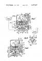
- FIG. 1is a sectional view, partially schematic, of a pump and of one embodiment of apparatus constituting this invention for operating with the pump to control the pressure of fluid from the pump;
- FIG. 2is a sectional view similar to that shown in FIG. 1 but with the apparatus in position for discontinuing the operation of the pump;
- FIG. 3is an enlarged fragmentary elevational view of sensors included in the apparatus of FIGS. 1 and 2;
- FIG. 4is a sectional view, partially schematic, of another embodiment of apparatus constituting this operation for operating with a pump to control the pressure of fluid from the pump;
- FIG. 5is a perspective view of the embodiment shown in FIG. 4.
- a pump generally indicated at 10is provided for pumping fluid at a controlled rate to a patient 14 on a positive basis.
- the pump 10may be a volumetric pump such as disclosed and claimed in U.S. Pat. No. 3,985,133. Such a pump is advantageous because it provides a flow of a pre-selected volume of fluid at a precise rate to a patient. However, any other type of pump may also be used.
- U.S. Pat. No. 3,985,133also discloses a disposable cassette for use with the pump.
- FIG. 1shows the pump and the disposable cassette in broken lines.
- a disposable cassette generally indicated at 12is coupled to the disposable cassette in the pump 10 to receive fluid from the disposable cassette in the pump and pass the fluid to the receiver such as the patient 14.
- sensing apparatus generally indicated at 16becomes operative to discontinue the operation of the pump. In this way, the pressure of the fluid introduced to the patient is controlled within pre-selected limits.
- the cassette 12is shown in some detail in FIGS. 1 and 2.
- the cassette 12includes a housing 20 having detent means such as tongues 22 disposed externally on opposite sides of the housing.
- the housing 20is shaped to define conduit means including an inlet line 24, an outlet line 26 and a chamber 28 between the inlet and outlet lines.
- the chamber 28communicates with the inlet line 24 and the outlet line 26.
- Resilient meanssuch as a diaphragm 30 is stretched across the chamber 28 between opposite sides of the housing 20.
- An actuatable arm 32rests on the diaphragm and extends upwardly from the diaphragm through an aperture or opening 34 in the housing. In this way, the arm 32 is captured by the aperture 34.
- the arm 32is disposed in cooperative relationship with a reinforcement 33 which extends from the diaphragm.
- the aperture or opening 34communicates with a passage 35 which has a dimension converging towards the relatively narrow dimensions of the aperture or opening 34.
- the arm 32engages resilient means such as a diaphragm 36 on the face of the pump 10.
- the diaphragm 36may have a construction similar to that of the diaphragm 30.
- the diaphragm 36supports an arm 38 which extends upwardly through a guide aperture 40 in a housing 42 so as to be guided for movement only in a vertical direction.
- a constrained spring 43is disposed between the housing 42 and a member 45 seated against the diaphragm 36.
- a flag 44is carried at the upper end of the arm 38 and is pivotable at one end on a pin 46 as a fulcrum.
- the flag 44carries a light source 48.
- a pair of bracket members 50are supported on the housing 42.
- Spring members 52are supported between the housing 42 and the bracket members 50.
- the spring members 52are provided with spring arms 54 which include detent means 56 for co-operating with the detent means 22 on the disposable cassette to hold the cassette in releasable relationship.
- a lever arm 60extends through a threaded aperture in one of the bracket members 50.
- the lever arm 60receives the knob 64, which is manually rotatable to adjust the vertical positioning of the lever arm 60.
- the lever arm 60engages the free end of a spring arm 70, the other end of which is attached to the pump housing 42.
- a bracket 74is attached to the housing 42 as by a nut-and-bolt arrangement 76.
- the bracket 74carries a photo sensor 78.
- the pump 10When operative, the pump 10 introduces fluid to the inlet line 24. This fluid flows through the chamber 28 and the outlet line 26 to the patient 14. The maximum pressure of this fluid is dependent upon the setting of the knob 64.
- the diaphragm 36translates the movement of the arm 32 into a corresponding movement of the arm 38. This produces a corresponding pivotal movement of the flag 44 about the pin 46 as a fulcrum.
- the light source 48becomes aligned with the photocell 78. This causes the photocell 78 to become energized and produces a signal for interrupting the operation of the pump 10.
- the particular fluid pressure for energizing the photocell 78can be manually adjusted by rotating the knob 64. This causes the lever arm 60 to be adjusted vertically in position. The adjustment in the vertical position of the lever arm 60 in turn produces adjustments in the pivotal position of the spring arm 70. This in turn produces adjustments in the position at which the light source 48 becomes level with the photocell 78 to energize the photocell.
- the apparatus described abovehas certain important advantages. It provides for a flow of fluid from a pump to a patient at controlled and pre-selected pressures dependent upon the setting of the knob 64. If the pressures of the fluid from the pump should increase above such controlled and pre-selected limits, the apparatus instantaneously senses such increases in the fluid pressure beyond such controlled and safe limits and causes an output signal to be produced for interrupting the operation of the pump.
- the apparatus described abovealso has other important advantages. For example, it provides a cassette which is easily and releasably coupled to the pump. Furthermore, the flow of fluid from the pump to the patient is only through the cassette. In this way, a different cassette can be substituted every time that a different patient is to receive the introduction of fluid or the same patient is to receive a different fluid. By providing such an arrangement, the pump can be easily adapted to provide fluid to a patient at relatively low levels of pressure without requiring that the pump be cleaned or sterilized after each use.
- the apparatus constituting this inventionalso has other advantages.
- itprovides all of the other elements within the pump housing 42.
- the diaphragm 36is disposed at the face of the pump. In this way, the diaphragm 36 helps to seal the pump and also translates the pressure of the fluid on the diaphragm 30 into a corresponding pivotal movement of the flag 44.
- all of the components other than those in the cassette 12are disposed in the pump housing 42, it will be appreciated that these components can also be disposed in a housing which is separate from the pump.
- FIGS. 4 and 5illustrate another embodiment of the invention.
- a cam 100 rotatable on a fulcrum 102is included.
- the camincludes a finger 104 for contacting a leaf spring 106, the leaf spring being attached at one end to a housing 108 by a screw or protuberance 110.
- the cam 100is shaped to move the finger 104 in a direction towards the screw or protruberance 110 in accordance with rotary movements of the cam in a clockwise direction and to move the finger in a direction away from the screw in accordance with rotary movements of the cam in a counter-clockwise direction.
- the cam 100is manually rotatable by a knob 112.
- the spring 106carries a flag 114 at the end opposite the screw 110.
- the flag 114may interrupt the light from a light source 116 to a sensor 118 when it has moved upwardly through a particular distance.
- the force required to move the flag 114 upwardly through this particular distanceis dependent upon the setting of the cam 100 since this setting controls the length of the torque arm between the finger 104 and the flag. In this way, the setting of the cam 100 controls the fluid pressure at which the light to the sensor 118 becomes interrupted.
Landscapes
- Health & Medical Sciences (AREA)
- Engineering & Computer Science (AREA)
- Hematology (AREA)
- Life Sciences & Earth Sciences (AREA)
- Vascular Medicine (AREA)
- Anesthesiology (AREA)
- Biomedical Technology (AREA)
- Heart & Thoracic Surgery (AREA)
- Veterinary Medicine (AREA)
- Public Health (AREA)
- Animal Behavior & Ethology (AREA)
- General Health & Medical Sciences (AREA)
- General Engineering & Computer Science (AREA)
- Mechanical Engineering (AREA)
- Reciprocating Pumps (AREA)
- External Artificial Organs (AREA)
Abstract
Description
Claims (40)
Priority Applications (2)
| Application Number | Priority Date | Filing Date | Title |
|---|---|---|---|
| US06/053,981US4277227A (en) | 1979-07-02 | 1979-07-02 | Apparatus for converting a pump to a controller |
| US06/321,192USRE31315E (en) | 1979-07-02 | 1981-11-13 | Apparatus for converting a pump to a controller |
Applications Claiming Priority (1)
| Application Number | Priority Date | Filing Date | Title |
|---|---|---|---|
| US06/053,981US4277227A (en) | 1979-07-02 | 1979-07-02 | Apparatus for converting a pump to a controller |
Related Child Applications (1)
| Application Number | Title | Priority Date | Filing Date |
|---|---|---|---|
| US06/321,192ReissueUSRE31315E (en) | 1979-07-02 | 1981-11-13 | Apparatus for converting a pump to a controller |
Publications (1)
| Publication Number | Publication Date |
|---|---|
| US4277227Atrue US4277227A (en) | 1981-07-07 |
Family
ID=21987898
Family Applications (1)
| Application Number | Title | Priority Date | Filing Date |
|---|---|---|---|
| US06/053,981Expired - LifetimeUS4277227A (en) | 1979-07-02 | 1979-07-02 | Apparatus for converting a pump to a controller |
Country Status (1)
| Country | Link |
|---|---|
| US (1) | US4277227A (en) |
Cited By (52)
| Publication number | Priority date | Publication date | Assignee | Title |
|---|---|---|---|---|
| WO1982000590A1 (en)* | 1980-08-25 | 1982-03-04 | Travenol Lab Baxter | Metering apparatus with downline pressure monitoring system |
| US4364386A (en)* | 1980-12-08 | 1982-12-21 | Imed Corporation | Apparatus for converting a pump to a controller |
| US4369780A (en)* | 1979-08-24 | 1983-01-25 | Sharp Kabushiki Kaisha | Blocking condition detection device in a medical fluid injection system |
| US4453931A (en)* | 1980-08-01 | 1984-06-12 | Oximetrix, Inc. | Intravenous metering device |
| US4460355A (en)* | 1982-06-11 | 1984-07-17 | Ivac Corporation | Fluid pressure monitoring system |
| EP0121931A2 (en) | 1983-04-11 | 1984-10-17 | Ivac Corporation | Fault detection apparatus for parenteral infusion system |
| WO1984004685A1 (en)* | 1983-05-23 | 1984-12-06 | Baxter Travenol Lab | Differential occlusion sensing method and apparatus |
| US4563179A (en)* | 1982-04-28 | 1986-01-07 | Sharp Kabushiki Kaisha | Blocking condition detection device in a fluid injection system |
| US4613325A (en)* | 1982-07-19 | 1986-09-23 | Abrams Lawrence M | Flow rate sensing device |
| US4648869A (en)* | 1985-12-04 | 1987-03-10 | American Hospital Supply Corporation | Automatic infiltration detection system and method |
| EP0258474A1 (en)* | 1986-09-01 | 1988-03-09 | Lawrence M. Abrams | Flow rate sensing device |
| US4747828A (en)* | 1986-12-09 | 1988-05-31 | Fisher Scientific Group | IV fluid line occlusion detector |
| US4752289A (en)* | 1985-03-20 | 1988-06-21 | Vi-Tal Hospital Products Ltd. | Infusion apparatus |
| USD299538S (en) | 1985-05-01 | 1989-01-24 | Vi-Tal Hospital Products, Ltd. | Pressure responsive chamber for monitoring pressure in an infusion set |
| US4836752A (en)* | 1987-11-02 | 1989-06-06 | Fisher Scientific Company | Partial restriction detector |
| US4994035A (en)* | 1988-05-11 | 1991-02-19 | Klaus Mokros | Pressure-transmitting diaphragm system for infusions |
| US5132500A (en)* | 1991-02-11 | 1992-07-21 | Micro Pneumatic Logic, Inc. | Differential pressure switch with sealed contacts |
| US5154700A (en)* | 1990-08-13 | 1992-10-13 | Danby Medical Limited | Arrangement for monitoring fluid flow during intravenous supply to a patient |
| US5276610A (en)* | 1989-04-28 | 1994-01-04 | Sharp Kabushiki Kaisha | Display device for indicating the internal pressure of the tube of an infusion pump |
| US5399171A (en)* | 1991-06-10 | 1995-03-21 | Baxter International Inc. | Intravenous metering monitoring device |
| US5863185A (en)* | 1994-10-05 | 1999-01-26 | Franklin Electric Co. | Liquid pumping system with cooled control module |
| US5925825A (en)* | 1994-10-05 | 1999-07-20 | Franklin Electric Co., Inc. | Clamp and cup securing strain gauge cell adjacent pressure transmitting diaphragm |
| WO2002004047A3 (en)* | 2000-07-07 | 2002-08-22 | Fluidsense Corp | Pump cassette with controlled pump force |
| JP2005527334A (en)* | 2002-05-28 | 2005-09-15 | マコスタ メディカル ユーエスエイ エルエルシー | Method and apparatus for reducing the risk of intraneuronal injection during the implementation of nerve block anesthesia |
| US20050222622A1 (en)* | 2002-02-11 | 2005-10-06 | Gold-T Tech, Inc. | Method for preventing thrombus formation |
| US20070088265A1 (en)* | 2004-03-05 | 2007-04-19 | Markus Butikofer | Adapter and pump interface for measuring pressure on an infusion pump |
| US20080065026A1 (en)* | 2000-06-16 | 2008-03-13 | Novo Nordisk A/S | Injection Device |
| EP2022519A1 (en)* | 2007-08-10 | 2009-02-11 | F. Hoffmann-La Roche AG | Device for detecting a pressure change in the liquid path of a micro dosing apparatus |
| US20090062748A1 (en)* | 2006-03-10 | 2009-03-05 | Novo Nordisk A/S | Injection Device Having a Gearing Arrangement |
| US20090254027A1 (en)* | 2006-03-10 | 2009-10-08 | Novo Nordisk A/S | Injection Device and a Method of Changing a Cartridge in the Device |
| US20090326455A1 (en)* | 2008-06-26 | 2009-12-31 | Calibra Medical, Inc. | Disposable infusion device with occlusion detector |
| US20110152762A1 (en)* | 2009-12-23 | 2011-06-23 | Hershey Adrienne A | Enteral Feeding Catheter Assembly Incorporating An Indicator |
| US8152751B2 (en) | 2007-02-09 | 2012-04-10 | Baxter International Inc. | Acoustic access disconnection systems and methods |
| US8197450B2 (en) | 2005-04-24 | 2012-06-12 | Novo Nordisk A/S | Injection device |
| US8226618B2 (en) | 2006-05-16 | 2012-07-24 | Novo Nordisk A/S | Gearing mechanism for an injection device |
| WO2012085697A3 (en)* | 2010-12-10 | 2012-11-22 | Kimberly-Clark Worldwide, Inc. | Infusion apparatus with flow indicator |
| US8353878B2 (en) | 2007-03-23 | 2013-01-15 | Novo Nordisk A/S | Injection device comprising a locking nut |
| CN103470482A (en)* | 2013-08-30 | 2013-12-25 | 张仙驰 | Silicon-controlled water pump pressure regulation control device |
| US8700133B2 (en) | 2012-06-18 | 2014-04-15 | Smart Iv Llc | Apparatus and method for monitoring catheter insertion |
| US9192727B2 (en) | 2006-05-18 | 2015-11-24 | Novo Nordisk A/S | Injection device with mode locking means |
| US9383288B2 (en) | 2008-06-26 | 2016-07-05 | Gambro Lundia Ab | Method and device for processing a time-dependent measurement signal |
| US9433356B2 (en) | 2009-06-26 | 2016-09-06 | Gambro Lundia Ab | Devices, a computer program product and a method for data extraction |
| CN106139301A (en)* | 2016-07-18 | 2016-11-23 | 丁松华 | A kind of nursing in operating room venous transfusion anti-intrusion device |
| US9533106B2 (en) | 2011-12-29 | 2017-01-03 | Novo Nordisk A/S | Torsion-spring based wind-up auto injector pen with dial-up/dial-down mechanism |
| AU2015268574B2 (en)* | 2010-12-10 | 2017-01-19 | Avent, Inc. | Infusion apparatus with flow indicator |
| US9597482B2 (en) | 2012-06-18 | 2017-03-21 | Smart Iv Llc | Apparatus and method for monitoring catheter insertion |
| USRE46363E1 (en) | 2004-10-21 | 2017-04-11 | Novo Nordisk A/S | Dial-down mechanism for wind-up pen |
| US9895109B2 (en) | 2013-03-20 | 2018-02-20 | Gambro Lundia Ab | Monitoring of cardiac arrest in a patient connected to an extracorporeal blood processing apparatus |
| US10413654B2 (en) | 2015-12-22 | 2019-09-17 | Baxter International Inc. | Access disconnection system and method using signal metrics |
| US10463778B2 (en) | 2007-02-09 | 2019-11-05 | Baxter International Inc. | Blood treatment machine having electrical heartbeat analysis |
| US10980431B2 (en) | 2009-12-28 | 2021-04-20 | Gambro Lundia Ab | Apparatus and method for prediction of rapid symptomatic blood pressure decrease |
| JP2022502196A (en)* | 2018-10-03 | 2022-01-11 | 武田薬品工業株式会社 | Detection assembly for injection pumps |
Citations (9)
| Publication number | Priority date | Publication date | Assignee | Title |
|---|---|---|---|---|
| US1568035A (en)* | 1924-06-07 | 1925-12-29 | Reynolds Brake Corp | Automatic cut-out |
| US2435143A (en)* | 1945-01-01 | 1948-01-27 | Milwhite Co Inc | Switch controlling assembly |
| US3091239A (en)* | 1958-08-25 | 1963-05-28 | Moeller Wilhelm | Apparatus for intravasal injection of gaseous and liquid media |
| US3490342A (en)* | 1967-04-18 | 1970-01-20 | United Electric Controls Co | Pressure control device |
| US3738776A (en)* | 1970-09-24 | 1973-06-12 | Equip Menagen Soc Fr | Pumping device, especially for water supply |
| US3855515A (en)* | 1972-03-06 | 1974-12-17 | Waters Associates Inc | Motor control circuit |
| US3985133A (en)* | 1974-05-28 | 1976-10-12 | Imed Corporation | IV pump |
| US4131393A (en)* | 1977-01-21 | 1978-12-26 | Altex Scientific, Inc. | Fluid pump mechanism |
| US4142524A (en)* | 1977-06-02 | 1979-03-06 | Andros Incorporated | Cassette for intravenous delivery system |
- 1979
- 1979-07-02USUS06/053,981patent/US4277227A/ennot_activeExpired - Lifetime
Patent Citations (9)
| Publication number | Priority date | Publication date | Assignee | Title |
|---|---|---|---|---|
| US1568035A (en)* | 1924-06-07 | 1925-12-29 | Reynolds Brake Corp | Automatic cut-out |
| US2435143A (en)* | 1945-01-01 | 1948-01-27 | Milwhite Co Inc | Switch controlling assembly |
| US3091239A (en)* | 1958-08-25 | 1963-05-28 | Moeller Wilhelm | Apparatus for intravasal injection of gaseous and liquid media |
| US3490342A (en)* | 1967-04-18 | 1970-01-20 | United Electric Controls Co | Pressure control device |
| US3738776A (en)* | 1970-09-24 | 1973-06-12 | Equip Menagen Soc Fr | Pumping device, especially for water supply |
| US3855515A (en)* | 1972-03-06 | 1974-12-17 | Waters Associates Inc | Motor control circuit |
| US3985133A (en)* | 1974-05-28 | 1976-10-12 | Imed Corporation | IV pump |
| US4131393A (en)* | 1977-01-21 | 1978-12-26 | Altex Scientific, Inc. | Fluid pump mechanism |
| US4142524A (en)* | 1977-06-02 | 1979-03-06 | Andros Incorporated | Cassette for intravenous delivery system |
Cited By (88)
| Publication number | Priority date | Publication date | Assignee | Title |
|---|---|---|---|---|
| US4369780A (en)* | 1979-08-24 | 1983-01-25 | Sharp Kabushiki Kaisha | Blocking condition detection device in a medical fluid injection system |
| US4453931A (en)* | 1980-08-01 | 1984-06-12 | Oximetrix, Inc. | Intravenous metering device |
| US4394862A (en)* | 1980-08-25 | 1983-07-26 | Baxter Travenol Laboratories, Inc. | Metering apparatus with downline pressure monitoring system |
| WO1982000590A1 (en)* | 1980-08-25 | 1982-03-04 | Travenol Lab Baxter | Metering apparatus with downline pressure monitoring system |
| US4364386A (en)* | 1980-12-08 | 1982-12-21 | Imed Corporation | Apparatus for converting a pump to a controller |
| US4563179A (en)* | 1982-04-28 | 1986-01-07 | Sharp Kabushiki Kaisha | Blocking condition detection device in a fluid injection system |
| US4460355A (en)* | 1982-06-11 | 1984-07-17 | Ivac Corporation | Fluid pressure monitoring system |
| US4613325A (en)* | 1982-07-19 | 1986-09-23 | Abrams Lawrence M | Flow rate sensing device |
| EP0121931A2 (en) | 1983-04-11 | 1984-10-17 | Ivac Corporation | Fault detection apparatus for parenteral infusion system |
| WO1984004685A1 (en)* | 1983-05-23 | 1984-12-06 | Baxter Travenol Lab | Differential occlusion sensing method and apparatus |
| AU571521B2 (en)* | 1983-05-23 | 1988-04-21 | Baxter International Inc. | Differential occlusion sensing method and apparatus |
| US4752289A (en)* | 1985-03-20 | 1988-06-21 | Vi-Tal Hospital Products Ltd. | Infusion apparatus |
| EP0375673A3 (en)* | 1985-03-20 | 1990-08-01 | Knight, Robert Leonard Harry | An infusion apparatus |
| USD299538S (en) | 1985-05-01 | 1989-01-24 | Vi-Tal Hospital Products, Ltd. | Pressure responsive chamber for monitoring pressure in an infusion set |
| US4648869A (en)* | 1985-12-04 | 1987-03-10 | American Hospital Supply Corporation | Automatic infiltration detection system and method |
| EP0258474A1 (en)* | 1986-09-01 | 1988-03-09 | Lawrence M. Abrams | Flow rate sensing device |
| US4747828A (en)* | 1986-12-09 | 1988-05-31 | Fisher Scientific Group | IV fluid line occlusion detector |
| US4836752A (en)* | 1987-11-02 | 1989-06-06 | Fisher Scientific Company | Partial restriction detector |
| US4994035A (en)* | 1988-05-11 | 1991-02-19 | Klaus Mokros | Pressure-transmitting diaphragm system for infusions |
| US5276610A (en)* | 1989-04-28 | 1994-01-04 | Sharp Kabushiki Kaisha | Display device for indicating the internal pressure of the tube of an infusion pump |
| US5154700A (en)* | 1990-08-13 | 1992-10-13 | Danby Medical Limited | Arrangement for monitoring fluid flow during intravenous supply to a patient |
| US5132500A (en)* | 1991-02-11 | 1992-07-21 | Micro Pneumatic Logic, Inc. | Differential pressure switch with sealed contacts |
| US5399171A (en)* | 1991-06-10 | 1995-03-21 | Baxter International Inc. | Intravenous metering monitoring device |
| US5863185A (en)* | 1994-10-05 | 1999-01-26 | Franklin Electric Co. | Liquid pumping system with cooled control module |
| US5925825A (en)* | 1994-10-05 | 1999-07-20 | Franklin Electric Co., Inc. | Clamp and cup securing strain gauge cell adjacent pressure transmitting diaphragm |
| US8333739B2 (en) | 2000-06-16 | 2012-12-18 | Novo Nordisk A/S | Injection device |
| US9022991B2 (en) | 2000-06-16 | 2015-05-05 | Novo Nordisk A/S | Injection device |
| US8206361B2 (en) | 2000-06-16 | 2012-06-26 | Novo Nordisk A/S | Injection device |
| US8267899B2 (en) | 2000-06-16 | 2012-09-18 | Novo Nordisk A/S | Injection device |
| US20080065026A1 (en)* | 2000-06-16 | 2008-03-13 | Novo Nordisk A/S | Injection Device |
| US10245383B2 (en) | 2000-06-16 | 2019-04-02 | Novo Nordisk A/S | Injection device |
| US8202256B2 (en) | 2000-06-16 | 2012-06-19 | Novo Nordisk A/S | Injection device |
| WO2002004047A3 (en)* | 2000-07-07 | 2002-08-22 | Fluidsense Corp | Pump cassette with controlled pump force |
| US8603086B2 (en) | 2002-02-11 | 2013-12-10 | Gold-T Tech, Inc. | Method for preventing thrombus formation |
| US20050222622A1 (en)* | 2002-02-11 | 2005-10-06 | Gold-T Tech, Inc. | Method for preventing thrombus formation |
| JP2005527334A (en)* | 2002-05-28 | 2005-09-15 | マコスタ メディカル ユーエスエイ エルエルシー | Method and apparatus for reducing the risk of intraneuronal injection during the implementation of nerve block anesthesia |
| EP1531893A4 (en)* | 2002-05-28 | 2008-05-21 | Macosta Medical Usa L L C | Method and appratus to decrease the risk of intraneuronal injection during administration of nerve block anesthesia |
| US20070088265A1 (en)* | 2004-03-05 | 2007-04-19 | Markus Butikofer | Adapter and pump interface for measuring pressure on an infusion pump |
| USRE46363E1 (en) | 2004-10-21 | 2017-04-11 | Novo Nordisk A/S | Dial-down mechanism for wind-up pen |
| US8641683B2 (en) | 2005-04-24 | 2014-02-04 | Novo Nordisk A/S | Injection device |
| US8197450B2 (en) | 2005-04-24 | 2012-06-12 | Novo Nordisk A/S | Injection device |
| US8298194B2 (en) | 2006-03-10 | 2012-10-30 | Novo Nordisk A/S | Injection device and a method of changing a cartridge in the device |
| US8361036B2 (en) | 2006-03-10 | 2013-01-29 | Novo Nordisk A/S | Injection device having a gearing arrangement |
| US20090062748A1 (en)* | 2006-03-10 | 2009-03-05 | Novo Nordisk A/S | Injection Device Having a Gearing Arrangement |
| US20090254027A1 (en)* | 2006-03-10 | 2009-10-08 | Novo Nordisk A/S | Injection Device and a Method of Changing a Cartridge in the Device |
| US8226618B2 (en) | 2006-05-16 | 2012-07-24 | Novo Nordisk A/S | Gearing mechanism for an injection device |
| US8900204B2 (en) | 2006-05-16 | 2014-12-02 | Novo Nordisk A/S | Gearing mechanism for an injection device |
| US9192727B2 (en) | 2006-05-18 | 2015-11-24 | Novo Nordisk A/S | Injection device with mode locking means |
| US8920355B2 (en) | 2007-02-09 | 2014-12-30 | Baxter International Inc. | Acoustic access disconnection systems and methods |
| US8603020B2 (en) | 2007-02-09 | 2013-12-10 | Baxter International Inc. | Ultrasound access disconnection systems and methods |
| US9138528B2 (en) | 2007-02-09 | 2015-09-22 | Baxter International Inc. | Acoustic access disconnection systems and methods |
| US9950105B2 (en) | 2007-02-09 | 2018-04-24 | Baxter International Inc. | Blood treatment and electrical blood leak detection device therefore |
| US10463778B2 (en) | 2007-02-09 | 2019-11-05 | Baxter International Inc. | Blood treatment machine having electrical heartbeat analysis |
| US8152751B2 (en) | 2007-02-09 | 2012-04-10 | Baxter International Inc. | Acoustic access disconnection systems and methods |
| US8795217B2 (en) | 2007-02-09 | 2014-08-05 | Baxter International Inc. | Acoustic access disconnection systems and methods |
| US9089654B2 (en) | 2007-02-09 | 2015-07-28 | Baxter International Inc. | Acoustic access disconnection systems and methods |
| US9352078B2 (en) | 2007-02-09 | 2016-05-31 | Baxter International Inc. | Electrical heartbeat access disconnection systems |
| US8353878B2 (en) | 2007-03-23 | 2013-01-15 | Novo Nordisk A/S | Injection device comprising a locking nut |
| WO2009021705A1 (en)* | 2007-08-10 | 2009-02-19 | Roche Diagnostics Gmbh | Device for detecting a pressure change in the liquid path of a micro dosing apparatus |
| EP2022519A1 (en)* | 2007-08-10 | 2009-02-11 | F. Hoffmann-La Roche AG | Device for detecting a pressure change in the liquid path of a micro dosing apparatus |
| WO2009021343A1 (en)* | 2007-08-10 | 2009-02-19 | F. Hoffmann-La Roche Ag | Micro dosing apparatus with diaphragm for detecting a pressure change in the liquid path |
| US20090326455A1 (en)* | 2008-06-26 | 2009-12-31 | Calibra Medical, Inc. | Disposable infusion device with occlusion detector |
| WO2010051079A3 (en)* | 2008-06-26 | 2010-08-19 | Calibra Medical, Inc. | Disposable infusion device with occlusion detector |
| US9442036B2 (en) | 2008-06-26 | 2016-09-13 | Gambro Lundia Ab | Methods and devices for monitoring the integrity of a fluid connection |
| US8361030B2 (en) | 2008-06-26 | 2013-01-29 | Calibra Medical, Inc. | Disposable infusion device with occlusion detector |
| US9383288B2 (en) | 2008-06-26 | 2016-07-05 | Gambro Lundia Ab | Method and device for processing a time-dependent measurement signal |
| US11300474B2 (en) | 2008-06-26 | 2022-04-12 | Gambro Lundia Ab | Methods and devices for monitoring the integrity of a fluid connection |
| US9433356B2 (en) | 2009-06-26 | 2016-09-06 | Gambro Lundia Ab | Devices, a computer program product and a method for data extraction |
| US9132064B2 (en) | 2009-12-23 | 2015-09-15 | Avent, Inc. | Enteral feeding catheter assembly incorporating an indicator |
| US10085922B2 (en) | 2009-12-23 | 2018-10-02 | Avent, Inc. | Enteral feeding catheter assembly incorporating an indicator |
| US20110152762A1 (en)* | 2009-12-23 | 2011-06-23 | Hershey Adrienne A | Enteral Feeding Catheter Assembly Incorporating An Indicator |
| US10980431B2 (en) | 2009-12-28 | 2021-04-20 | Gambro Lundia Ab | Apparatus and method for prediction of rapid symptomatic blood pressure decrease |
| US8439862B2 (en) | 2010-12-10 | 2013-05-14 | Kimberly-Clark Worldwide, Inc. | Infusion apparatus with flow indicator |
| WO2012085697A3 (en)* | 2010-12-10 | 2012-11-22 | Kimberly-Clark Worldwide, Inc. | Infusion apparatus with flow indicator |
| AU2015268574B2 (en)* | 2010-12-10 | 2017-01-19 | Avent, Inc. | Infusion apparatus with flow indicator |
| JP2014500778A (en)* | 2010-12-10 | 2014-01-16 | キンバリー クラーク ワールドワイド インコーポレイテッド | Infusion device with flow indicator |
| US9180247B2 (en) | 2010-12-10 | 2015-11-10 | Avent, Inc. | Infusion apparatus with flow indicator |
| AU2011346709B2 (en)* | 2010-12-10 | 2015-12-24 | Avent, Inc. | Infusion apparatus with flow indicator |
| US9533106B2 (en) | 2011-12-29 | 2017-01-03 | Novo Nordisk A/S | Torsion-spring based wind-up auto injector pen with dial-up/dial-down mechanism |
| US9597482B2 (en) | 2012-06-18 | 2017-03-21 | Smart Iv Llc | Apparatus and method for monitoring catheter insertion |
| US8700133B2 (en) | 2012-06-18 | 2014-04-15 | Smart Iv Llc | Apparatus and method for monitoring catheter insertion |
| US9895109B2 (en) | 2013-03-20 | 2018-02-20 | Gambro Lundia Ab | Monitoring of cardiac arrest in a patient connected to an extracorporeal blood processing apparatus |
| CN103470482A (en)* | 2013-08-30 | 2013-12-25 | 张仙驰 | Silicon-controlled water pump pressure regulation control device |
| CN103470482B (en)* | 2013-08-30 | 2015-07-29 | 张仙驰 | Controllable silicon water-aspirator pressure control set for adjusting |
| US10413654B2 (en) | 2015-12-22 | 2019-09-17 | Baxter International Inc. | Access disconnection system and method using signal metrics |
| CN106139301B (en)* | 2016-07-18 | 2019-08-13 | 丁松华 | A kind of nursing in operating room venous transfusion anti-intrusion device |
| CN106139301A (en)* | 2016-07-18 | 2016-11-23 | 丁松华 | A kind of nursing in operating room venous transfusion anti-intrusion device |
| JP2022502196A (en)* | 2018-10-03 | 2022-01-11 | 武田薬品工業株式会社 | Detection assembly for injection pumps |
Similar Documents
| Publication | Publication Date | Title |
|---|---|---|
| US4277227A (en) | Apparatus for converting a pump to a controller | |
| USRE31315E (en) | Apparatus for converting a pump to a controller | |
| US4300552A (en) | Apparatus for controlling the flow of intravenous fluid to a patient | |
| US4207871A (en) | System for controlling the flow of intravenous fluids to a patient | |
| JP7232528B2 (en) | electronic vacuum regulator device | |
| US11617870B2 (en) | System and method for automatically adjusting an external ventricular drain | |
| CA1110137A (en) | Intravenous liquid pumping system and method | |
| EP1964584B1 (en) | Positive pressure infusion system having downstream resistance measurement capability | |
| US4670006A (en) | Fluid and air infusion device | |
| US5520652A (en) | Methods and apparatus for control of vacuum and pressure for surgical procedures | |
| GB2031558A (en) | Apparatus for controlling the flow of intravenous fluid to a patient | |
| US4620690A (en) | Modular flow control cassette | |
| US4108575A (en) | Obtaining desired flow rate from roller pump despite varying the hose means | |
| US5795328A (en) | Vacuum system and a method of operating a vacuum system | |
| EP0481459A1 (en) | Apparatus for continuous positive airway pressure breathing (CPAP) | |
| WO1984004460A1 (en) | I.v. flow regulator | |
| WO1992008179A1 (en) | Proportional valve and pressure control system | |
| NL7908356A (en) | NARCOSE DEVICE. | |
| US4364386A (en) | Apparatus for converting a pump to a controller | |
| US5599308A (en) | Intermittent vacuum regulator with timing module | |
| US4314567A (en) | Drop controller | |
| GB2089497A (en) | Control of pressure of fluid delivered by a pump | |
| CA1157314A (en) | Apparatus for converting a pump to a controller | |
| WO2000076563A1 (en) | Intermittent regulator | |
| US5720313A (en) | Flow rate control system |
Legal Events
| Date | Code | Title | Description |
|---|---|---|---|
| STCF | Information on status: patent grant | Free format text:PATENTED CASE | |
| AS | Assignment | Owner name:IMED CORPORATION Free format text:MERGER;ASSIGNOR:IMED CORPORATION;REEL/FRAME:004367/0374 Effective date:19850220 | |
| AS | Assignment | Owner name:HENLEY INVESTMENTS, INC. Free format text:MERGER;ASSIGNOR:IMED CORPORATION;REEL/FRAME:004669/0518 Effective date:19861222 | |
| AS | Assignment | Owner name:NEWCO HENLEY HOLDINGS INC., A DE CORP. Free format text:ASSIGNMENT OF ASSIGNORS INTEREST.;ASSIGNOR:HENLEY MANAGEMENT, INC.,;REEL/FRAME:005026/0384 Effective date:19890130 Owner name:IMED PATENTS HOLDING COMPANY, INC., NEW HAMPSHIRE Free format text:ASSIGNMENT OF ASSIGNORS INTEREST.;ASSIGNOR:NEWCO HENLEY HOLDINGS INC.,;REEL/FRAME:005026/0345 Effective date:19890130 | |
| AS | Assignment | Owner name:GENERAL ELECTRIC CAPITAL CORPORATION, A CORP. OF N Free format text:SECURITY INTEREST;ASSIGNOR:ADVANCED MEDICAL TECHNOLOGIES, INC.;REEL/FRAME:005363/0927 Effective date:19900402 Owner name:ADVANCED MEDICAL TECHNOLOGIES, INC., A CORP. OF DE Free format text:ASSIGNMENT OF ASSIGNORS INTEREST.;ASSIGNOR:IMED PATENTS HOLDING COMPANY, INC.;REEL/FRAME:005363/0891 Effective date:19900402 Owner name:GENERAL ELECTRIC CAPITAL CORPORATION, A CORP. OF N Free format text:LICENSE;ASSIGNOR:IMED CORPORATION;REEL/FRAME:005363/0913 Effective date:19900402 | |
| AS | Assignment | Owner name:ADVANCED MEDICAL, INC., CALIFORNIA Free format text:CHANGE OF NAME;ASSIGNOR:ADVANCED MEDICAL TECHNOLOGIES, INC.;REEL/FRAME:008261/0420 Effective date:19900907 | |
| AS | Assignment | Owner name:ADVANCED MEDICAL TECHNOLOGIES, INC., CALIFORNIA Free format text:SECURITY INTEREST;ASSIGNOR:GENERAL ELECTRIC CAPITAL CORPORATION;REEL/FRAME:008401/0741 Effective date:19961126 Owner name:IMED CORPORATON, CALIFORNIA Free format text:ASSIGNMENT OF ASSIGNORS INTEREST;ASSIGNOR:ADVANCED MEDICAL, INC.;REEL/FRAME:008447/0245 Effective date:19961125 Owner name:IMED CORPORATION, CALIFORNIA Free format text:SECURITY INTEREST;ASSIGNOR:GENERAL ELECTRIC CAPITAL CORPORATION;REEL/FRAME:008454/0006 Effective date:19961126 | |
| AS | Assignment | Owner name:BANKERS TRUST COMPANY, NEW YORK Free format text:SECURITY INTEREST;ASSIGNOR:IVAC HOLDINGS, INC.;REEL/FRAME:008568/0540 Effective date:19961126 | |
| AS | Assignment | Owner name:ALARIS MEDICAL SYSTEMS, INC., CALIFORNIA Free format text:CHANGE OF NAME;ASSIGNOR:IVAC HOLDINGS, INC.;REEL/FRAME:011700/0538 Effective date:19970425 Owner name:IVAC HOLDINGS, INC., CALIFORNIA Free format text:MERGER;ASSIGNOR:IMED CORPORATION;REEL/FRAME:011700/0747 Effective date:19961126 |