US4276590A - Current sharing modular power system - Google Patents
Current sharing modular power systemDownload PDFInfo
- Publication number
- US4276590A US4276590AUS06/035,370US3537079AUS4276590AUS 4276590 AUS4276590 AUS 4276590AUS 3537079 AUS3537079 AUS 3537079AUS 4276590 AUS4276590 AUS 4276590A
- Authority
- US
- United States
- Prior art keywords
- current
- signal
- power
- output
- produce
- Prior art date
- Legal status (The legal status is an assumption and is not a legal conclusion. Google has not performed a legal analysis and makes no representation as to the accuracy of the status listed.)
- Expired - Lifetime
Links
- 238000004804windingMethods0.000claimsdescription7
- 238000003079width controlMethods0.000claimsdescription6
- 230000007423decreaseEffects0.000claimsdescription5
- 238000001914filtrationMethods0.000claims2
- 238000010586diagramMethods0.000description5
- 230000004048modificationEffects0.000description5
- 238000012986modificationMethods0.000description5
- XUIMIQQOPSSXEZ-UHFFFAOYSA-NSiliconChemical compound[Si]XUIMIQQOPSSXEZ-UHFFFAOYSA-N0.000description4
- 239000003990capacitorSubstances0.000description4
- 229910052710siliconInorganic materials0.000description4
- 239000010703siliconSubstances0.000description4
- 230000035559beat frequencyEffects0.000description2
- 230000001276controlling effectEffects0.000description2
- 238000009434installationMethods0.000description2
- 230000001105regulatory effectEffects0.000description2
- 239000012141concentrateSubstances0.000description1
- 230000003247decreasing effectEffects0.000description1
- 230000017525heat dissipationEffects0.000description1
- 230000001360synchronised effectEffects0.000description1
Images


Classifications
- H—ELECTRICITY
- H02—GENERATION; CONVERSION OR DISTRIBUTION OF ELECTRIC POWER
- H02J—CIRCUIT ARRANGEMENTS OR SYSTEMS FOR SUPPLYING OR DISTRIBUTING ELECTRIC POWER; SYSTEMS FOR STORING ELECTRIC ENERGY
- H02J3/00—Circuit arrangements for AC mains or AC distribution networks
- H02J3/38—Arrangements for parallely feeding a single network by two or more generators, converters or transformers
- H02J3/46—Controlling of the sharing of output between the generators, converters, or transformers
- H—ELECTRICITY
- H02—GENERATION; CONVERSION OR DISTRIBUTION OF ELECTRIC POWER
- H02J—CIRCUIT ARRANGEMENTS OR SYSTEMS FOR SUPPLYING OR DISTRIBUTING ELECTRIC POWER; SYSTEMS FOR STORING ELECTRIC ENERGY
- H02J1/00—Circuit arrangements for DC mains or DC distribution networks
- H02J1/10—Parallel operation of DC sources
- H02J1/102—Parallel operation of DC sources being switching converters
- H—ELECTRICITY
- H02—GENERATION; CONVERSION OR DISTRIBUTION OF ELECTRIC POWER
- H02J—CIRCUIT ARRANGEMENTS OR SYSTEMS FOR SUPPLYING OR DISTRIBUTING ELECTRIC POWER; SYSTEMS FOR STORING ELECTRIC ENERGY
- H02J5/00—Circuit arrangements for transfer of electric power between AC networks and DC networks
- H—ELECTRICITY
- H02—GENERATION; CONVERSION OR DISTRIBUTION OF ELECTRIC POWER
- H02M—APPARATUS FOR CONVERSION BETWEEN AC AND AC, BETWEEN AC AND DC, OR BETWEEN DC AND DC, AND FOR USE WITH MAINS OR SIMILAR POWER SUPPLY SYSTEMS; CONVERSION OF DC OR AC INPUT POWER INTO SURGE OUTPUT POWER; CONTROL OR REGULATION THEREOF
- H02M3/00—Conversion of DC power input into DC power output
- H02M3/22—Conversion of DC power input into DC power output with intermediate conversion into AC
- H02M3/24—Conversion of DC power input into DC power output with intermediate conversion into AC by static converters
- H02M3/28—Conversion of DC power input into DC power output with intermediate conversion into AC by static converters using discharge tubes with control electrode or semiconductor devices with control electrode to produce the intermediate AC
- H02M3/325—Conversion of DC power input into DC power output with intermediate conversion into AC by static converters using discharge tubes with control electrode or semiconductor devices with control electrode to produce the intermediate AC using devices of a triode or a transistor type requiring continuous application of a control signal
- H02M3/335—Conversion of DC power input into DC power output with intermediate conversion into AC by static converters using discharge tubes with control electrode or semiconductor devices with control electrode to produce the intermediate AC using devices of a triode or a transistor type requiring continuous application of a control signal using semiconductor devices only
- H02M3/337—Conversion of DC power input into DC power output with intermediate conversion into AC by static converters using discharge tubes with control electrode or semiconductor devices with control electrode to produce the intermediate AC using devices of a triode or a transistor type requiring continuous application of a control signal using semiconductor devices only in push-pull configuration
- H02M3/3376—Conversion of DC power input into DC power output with intermediate conversion into AC by static converters using discharge tubes with control electrode or semiconductor devices with control electrode to produce the intermediate AC using devices of a triode or a transistor type requiring continuous application of a control signal using semiconductor devices only in push-pull configuration with automatic control of output voltage or current
Definitions
- the present inventionrelates generally to an electrical power system and particularly to a power system which includes circuitry to permit current sharing between a plurality of power modules which are coupled together to allow each module to supply the same current to a power distribution bus.
- circuits in the TTL and MOS familiesare often utilized to perform numerous digital functions.
- the circuit modules in these logic familiesare typically mounted on a circuit card which is capable of supporting large numbers of such circuit modules disposed in both rows and columns. In many instances, all available module positions on each card are occupied and, accordingly, all digital signals input and output from the card must be supplied to via a connector.
- each circuit cardrequires a highly regulated DC power supply to function properly.
- One approach to providing the regulated power necessaryis to provide a power source and regulator on each card. This approach is not entirely satisfactory as the power circuitry takes up space which might otherwise be useable for digital logic modules. This approach is also undesirable in systems having multiple circuit cards because the power system circuits must be duplicated on each circuit card which unnecessarily adds to system cost.
- a further disadvantage to mounting the power system on each cardis that heat dissipation becomes a problem which, if not solved, may give rise to circuit failures. Consequently, a central power source seems to offer a better solution to providing power to a plurality of circuit modules on one or more circuit cards.
- the DC power requirements of the subsequently modified systemare greater than those for the initially delivered system. It is, therefore, desirable to have a power system capable of providing the power requirements of the initially delivered system as well as for the system following subsequent modification.
- the power supplycan be designed initially to handle the load required by the initial system as well as that which might be experienced following subsequent modification. While this approach does permit providing sufficient electrical power for the system, it does contribute to higher system cost as an oversized power supply must be initially provided with a system.
- An approach to solving the problem of higher power supply cost in an initial system wherein subsequent modification appears likelyis to provide a power supply initially capable of handling the current load and subsequently add power supplies in parallel with the initial supply to handle the increased load due to subsequent system modification.
- the difficulty with this approachis that typical power supplies, when coupled in parallel, do not necessarily share the current load. Indeed, in most instances, one of the power supplies will attempt to provide all of the power requirements while the other power supply does little if anything. When this occurs, the supply attempting to provide all the current may experience an overload condition which, if the supply is equipped with overload protection circuitry, will shut down thereby leaving the second supply to attempt to provide the system power requirement. If the second supply also has an overload protection circuit, it too will shut down leaving the system without power.
- a modular power systemwhich utilizes a power inverter circuit for converting DC current to a high frequency alternating current.
- the output of the inverteris coupled by way of a transformer to a rectifier and a filter network which produces at its output a substantially ripple-free DC voltage which, for the embodiment exemplified in the drawings, is 5 volts at a current level ranging from 0 to 150 amperes per module.
- a voltage sense circuitis coupled between each module and the common power distribution bus which connects to the filter output of each module.
- a current sensing circuitis provided to sense the current at the output of each power inverter.
- a difference signalis developed having a magnitude related to the difference between the current at the output of one particular power inverter and the current at the output of a second power inverter in another module providing power to the common power distribution bus.
- This difference signal and the voltage sense signalare combined together to develop a pulse width control signal which in turn controls the pulse width of the signal developed at the output of each power inverter.
- Each power inverteris operative in response to the pulse width control signal so that it will increase its current output when the pulse width control signal indicates that the load is not being shared evenly and the other power module is supplying more current and decreases the pulse width when the pulse width control signal indicates that the module is supplying more current to the load than the other power module.
- a further feature of the present inventionis that each of the power inverter circuits in different power modules is synchronized by a synchronizing circuit so that the inverter output signals are at exactly the same frequency. This is advantageous because the ripple occuring at the rectified and filtered output is thereby reduced to its minimum level because there is no beat frequency between the power inverter outputs.
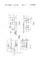
- FIG. 1is a block diagram of a power system according to the present invention having two power sharing modules coupled to a common load;
- FIG. 2is a circuit diagram of a typical full bridge inverter circuit which may be used as part of each power module designed according to the present invention
- FIG. 3shows a pulse width modulator and a driver circuit for controlling the operation of the inverter of FIG. 2;
- FIG. 4shows two compensation networks used in the system of FIG. 1;
- FIG. 5shows the components which may be used to construct the filter of FIG. 1;
- FIG. 6shows a synchronizing circuit which may be used in the system of FIG. 1.
- FIG. 1A block diagram of the current sharing modular power system of the present invention is illustrated by FIG. 1.
- An alternating current inputis provided at line 10 which is applied to the input of a conventional rectifier and filter network 12 which produces at its output 14 a direct current voltage which, in an illustrative embodiment of the present invention, is typically in the order of 300 volts DC.
- the rectifier and filter network 12is operative in a conventional manner to convert the AC input to a substantially ripple free DC output.
- the direct current voltage at the output 14 from the rectifier and filter network 12is coupled by a line 16 to a first power module which is surrounded by the dotted line 18.
- the DC electric power from the output 14is coupled by a further line 20 to the input of a second power module which is surrounded by a dotted line 22.
- the circuitry of the first power module 18 and the second power module 22are substantially identical to each other and that the following description of the circuitry will concentrate primarily on the circuitry of one power module, namely the first power module 18.
- the direct current voltage appearing on wire 16enters the first power module 18 and is applied to a power inverter circuit 24 which converts the DC input thereto to an alternating current output appearing at line 26.
- the output at line 26comprises an alternating current signal having a frequency of 20 KHz and a peak to peak amplitude of approximately 600 volts.
- Both the positive and the negative going pulses appearing at line 26are pulse width modulated by the inverter 24 under control of pulse width modulation signals which are generated by the pulse width modulator circuit 28 and coupled thereto over the line 30.
- the output of the inverter circuit 24 appearing at line 26is coupled through a current sensing transformer 32 to a step-down power transformer 34 which drops the voltage appearing at the output of the inverter 24 to a voltage approximating the desired voltage to be applied to the power load R L which, for the system illustrated, is around 5 volts.
- the lower voltage alternating current signal appearing at line 36is applied to a conventional rectifier circuit 38 to convert the alternating current into a direct current which is thereafter filtered by a conventional LC filter 40 to produce a substantially ripple free DC output voltage at point 42.
- This voltageis then coupled by an appropriate power distribution network to the power load which is designated R L .
- This loadin a typical integrated circuit system, is a distributed one which is typically spread over a plurality of circuit boards with a power bus interconnecting all the circuit boards.
- the DC voltages appearing on line 20is converted by the second power module 22 to a DC voltage appearing at line 44 which is coupled directly to the power load R L as well.
- the modules according to the inventionoperate so that the voltage output of the first power module 18 and the second power module 22 are identical, and the current in the load R L is shared substantially equally between the power module 18 and the power module 22.
- the remainder of the circuitry to be discussed hereinafteris primarily operative to assure that the operation of the power module 18 and the power module 22 is adjusted so that the current in the load R L is shared evenly between the first power module 18 and the second power module 22.
- a current sensing transformer 32is provided between the power inverter 24 and the transformer 34.
- the current sensing transformer 32produces a signal in its secondary winding which is proportional to the current passing through its primary winding between the output 26 of inverter 24 and the transformer 34.
- the secondary voltage of transformer 32is rectified by diodes 46 to produce a DC signal at point 48 whose amplitude is porportional to the current flowing through the primary winding of current sensing transformer 32.
- a filter network 50is coupled to the secondary winding of the current sensing transformer 32 and also by a wire 52 to a corresponding filter network 56 in the second power module 22.
- the filter 50responds to the voltage signal appearing at point 48 to produce a DC voltage which is porportional to the current I 1 from the first module 18 to the load R L .
- the filter 56responds to the voltage signal at point 58 to produce a DC voltage which is proportional to the current I 2 from the second module 22 to the load R L .
- the filters 50 and 56act as two batteries bucking each other which produce a difference current in the network defined by the filters 50 and 56, the wires 52, 54 and 60 and the resistors R 3 and R 3 ' which is proportional to the difference between I 1 and I 2 .
- the difference current on line 54passes through resistor R 3 and produces a voltage (difference signal) across R 3 .
- the difference signalis then coupled through R 2 and by line 62 to the positive input of a comparator circuit 64 which, in the illustrative embodiment of the present invention, comprises a portion of the pulse width modulator module 28 and is particularly part of the integrated circuit by Silicon General known as SG3524.
- An output voltage sensing line 66is coupled to the power distribution network preferably at a position midway in the distributed load R L so that circuits at the far end of the distributed load will experience a voltage below that at the sense point but within the desired voltage tolerance and those circuits closer to the output of the LC filters are above that voltage sensed by the line 66 but also within the voltage tolerance.
- the sensed voltageis then applied through a resistor network including resistors R 4 and R 5 as well as through a compensation network 68 to the negative input of the amplifier circuit 64.
- a further compensation network 70couples between the output of the amplifier circuit 64 and its negative or inverting input.
- the amplifier circuit 64 and the pulse width modulator 28respond to the voltage sensed signal on line 66 as well as to the current difference signal on the line 54 so as to adjust the voltage and current appearing at the output point 42.
- the amplifier circuit 64causes the pulse width modulator 28 to widen the pulses being produced by the inverter circuit 24.
- the output voltage from the first power module 18is increased.
- the amplifier 64responds to the increased voltage to cause the pulse width modulator 28 to reduce the pulse width of pulses produced by the inverter circuit 24.
- the amplifier 64responds to the current difference signal on line 54 so as to either increase or decrease the pulse width of the signal produced at the output of the inverter 24.
- the pulse widthis increased whenever the difference signal indicates that the current I 2 is greater than the current I 1 .
- the pulse width of the pulses produced by the inverter 24is decreased whenever the difference signal on line 54 indicates that the current I 1 is greater than the current I 2 .
- the voltage sensing feedback which adjusts the inverter 24 operationis independent of the current sensing feedback which also adjusts the inverter 24 operation. Accordingly, either the sense line 66 or the line 54 may be coupled to a reference voltage and the other feedback network to the amplifier 64 will continue to operate in the manner described above.
- the operation of power module 22is substantially the same as described above for power module 18.
- the circuitry of FIG. 1also includes a synchronizing network 72 which couples to the pulse width modulator circuit 28 in power module 18 to the pulse width modulator circuit 74 in the second power module 22.
- the synchronizing network 72is operative to insure that the frequency of the pulses produced by the pulse width modulator circuit 28 and 74 are identical to each other. In this manner, the DC voltage appearing at the output point 42 from the first power module 18 and 44 from the second power module 22 have a ripple at exactly the same frequency and therefore, there is no beat frequency between them which would tend to increase the ripple voltage on the load R L .
- FIG. 2The circuit for a typical full bridge inverter 24 is illustrated in FIG. 2.
- the circuitry of FIG. 2is controlled by control signals which are applied thereto over the lines labeled a,b,c,d,e,f,g and h. These control signals are operative to cause transistors Q1 and Q4 to conduct during half of the cycle of the inverter and transistors Q2 and Q3 to be conductive during the other half of the cycle. In this manner, an alternating current is established through the current transformer 32 and the power transformer 34.
- the circuitry of FIG. 3is illustrative of that which is required for developing the control signals for controlling the operation of the full bridge inverter of FIG. 2.
- the module 100has signal inputs to the lines labeled j,k and l as well as control lines labeled m,n and o.
- the moduleproduces signals at its outputs labeled EA, CA, CB and EB which control the circuitry for developing the control signals on lines a,b,c,d,e,f,g and h.
- the amplifier circuit 64 of FIG. 1is actually located in module 100 with input pin 1 being the inverting input to the amplifier and pin 2 being the non-inverting input to the amplifier.
- the output of the amplifier which is coupled to the compensation network 70is pin 9 of the module 100.
- FIG. 4is a detailed circuit diagram illustrating the compensation networks 68 and 70 of FIG. 1. These compensation networks 68 and 70 are coupled into the circuitry of the system according to FIG. 1 in the manner clearly evident from the diagram of FIG. 4.
- FIG. 5illustrates a typical filter 50 of FIG. 1 which serves as a rectifier and filter to develop a DC voltage across the 1000 ohm resistor. This DC voltage is proportional to the current passing through the current sensing transformer 32.
- the filter 50 of FIG. 5may be easily constructed of other elements and in various other manners.
- FIG. 6illustrates the manner in which synchronization is achieved between the pulse width modulator 28 and pulse width modulator 74.
- the output of each of the oscillators in the Silicon General pulse width modulator chip SG3524are connected together as illustrated by the line with the m at either end.
- the lines labeled n and o of the module 100 in FIG. 3are respectively coupled by a capacitor and a resistor to ground each element having the value illustrated in FIG. 6. This establishes a period for the oscillator in one of the Silicon General SG3524 chips.
- the oscillator in the other pulse width modulator chiphas its lines labeled n and o coupled to a capacitor and a resistor as illustrated in FIG.
- the capacitorhaving half the capacitance of that coupled to the other pulse width modulator and the resistor having greater resistance than that coupled to the other pulse width modulator.
- the value selected for the resistor and capacitor illustrated at 102 in FIG. 6is operative to cause the period of the oscillator in the pulse width modulator in the second power module to be longer then that in the first power module. Accordingly, the signal output from the first pulse width modulator is the one which controls the operation of the pulse width modulator in the second power module.
- the system according to the present invention as illustrated in FIG. 1permits two identical power modules to be coupled together so as to permit current sharing between the modules when their outputs are connected together across a common load R L .
- the circuitryalso includes output current sensing and output voltage sensing, the combined network is operative to equally share the power delivered by the two modules to the common load.
- additional power modules identical to those illustrated in FIG. 1are coupled together in parallel so that the load current from the additional power modules is also coupled into the common load R L .
- the further power modulesadditionally include connections from the corresponding filter network therein to the line 52 and further connections to the synchronization network 72 so that the pulse width modulators of each of the power modules are operated at the same frequency.
- the further power modulesalso include an output voltage sensing line which is coupled to the common load at the same point as are the voltage sense lines of the two modules illustrated in FIG. 1. In this manner, the further power modules can respond in a proper manner to a falling output voltage across the common load.
- the further power modulesinclude internal current sensing circuitry, these further power modules when coupled to those in the sytem of FIG. 1, operate to share the power supplied by the modules coupled to the common load. In such a system, however, the difference signal developed is equal to the difference between the current supplied by one module and the average of the current supplied by the other modules.
Landscapes
- Engineering & Computer Science (AREA)
- Power Engineering (AREA)
- Inverter Devices (AREA)
- Continuous-Control Power Sources That Use Transistors (AREA)
- Dc-Dc Converters (AREA)
- Power Sources (AREA)
Abstract
Description
Claims (10)
Priority Applications (6)
| Application Number | Priority Date | Filing Date | Title |
|---|---|---|---|
| US06/035,370US4276590A (en) | 1979-04-30 | 1979-04-30 | Current sharing modular power system |
| DE19803012728DE3012728A1 (en) | 1979-04-30 | 1980-04-01 | COMMUNITY POWER SUPPLY SYSTEM |
| GB8012443AGB2047445B (en) | 1979-04-30 | 1980-04-15 | Current sharing system |
| FR8009430AFR2455808A1 (en) | 1979-04-30 | 1980-04-25 | MODULAR POWER SUPPLY MOUNTING WITH CURRENT DISTRIBUTION |
| AU57879/80AAU529786B2 (en) | 1979-04-30 | 1980-04-29 | Current sharing modular power system |
| JP5638780AJPS55147712A (en) | 1979-04-30 | 1980-04-30 | Power unit having current devided module |
Applications Claiming Priority (1)
| Application Number | Priority Date | Filing Date | Title |
|---|---|---|---|
| US06/035,370US4276590A (en) | 1979-04-30 | 1979-04-30 | Current sharing modular power system |
Publications (1)
| Publication Number | Publication Date |
|---|---|
| US4276590Atrue US4276590A (en) | 1981-06-30 |
Family
ID=21882253
Family Applications (1)
| Application Number | Title | Priority Date | Filing Date |
|---|---|---|---|
| US06/035,370Expired - LifetimeUS4276590A (en) | 1979-04-30 | 1979-04-30 | Current sharing modular power system |
Country Status (6)
| Country | Link |
|---|---|
| US (1) | US4276590A (en) |
| JP (1) | JPS55147712A (en) |
| AU (1) | AU529786B2 (en) |
| DE (1) | DE3012728A1 (en) |
| FR (1) | FR2455808A1 (en) |
| GB (1) | GB2047445B (en) |
Cited By (42)
| Publication number | Priority date | Publication date | Assignee | Title |
|---|---|---|---|---|
| US4371919A (en)* | 1981-04-29 | 1983-02-01 | Bell Telephone Laboratories, Incorporated | Load distribution among parallel DC-DC converters |
| US4425613A (en) | 1981-05-26 | 1984-01-10 | Sperry Corporation | Forced load sharing circuit for inverter power supply |
| US4426611A (en) | 1982-04-28 | 1984-01-17 | General Electric Company | Twelve pulse load commutated inverter drive system |
| US4468722A (en)* | 1982-07-28 | 1984-08-28 | Reliance Electric Company | Power supply having slope controlled output volt-ampere characteristic |
| US4472641A (en)* | 1983-01-28 | 1984-09-18 | Westinghouse Electric Corp. | Power supply apparatus |
| US4564742A (en)* | 1983-11-28 | 1986-01-14 | Esab Aktiebolag | Source of power for arc welding |
| US4598352A (en)* | 1983-05-02 | 1986-07-01 | International Standard Electric Corporation | Controlled parallel converter plant |
| US4677535A (en)* | 1985-04-30 | 1987-06-30 | Mitsubishi Denki Kabushiki Kaisha | Power conversion system |
| US4694193A (en)* | 1983-05-27 | 1987-09-15 | Siemens Aktiengesellschaft | Fault recognition circuit for parallel power supply devices feeding a user |
| US4694388A (en)* | 1985-08-10 | 1987-09-15 | U.S. Philips Corporation | Synchronizer for commonly clocked converters |
| US4748340A (en)* | 1986-11-17 | 1988-05-31 | Liberty Engineering, Inc. | Load share system |
| US4754161A (en)* | 1987-07-31 | 1988-06-28 | Westinghouse Electric Corp. | Circuit and method for paralleling AC electrical power systems |
| US4775800A (en)* | 1983-12-30 | 1988-10-04 | Westinghouse Elctric Corp. | Power-supply apparatus |
| US4947310A (en)* | 1988-05-30 | 1990-08-07 | Mitsubishi Denki Kabushiki Kaisha | Parallel operating system for alternate current output converters |
| US4950916A (en)* | 1988-08-25 | 1990-08-21 | Westinghouse Electric Corp. | Line voltage regulator |
| US5036452A (en)* | 1989-12-28 | 1991-07-30 | At&T Bell Laboratories | Current sharing control with limited output voltage range for paralleled power converters |
| EP0492396A1 (en)* | 1990-12-19 | 1992-07-01 | Mitsubishi Denki Kabushiki Kaisha | Parallel inverter system |
| EP0510601A1 (en)* | 1991-04-22 | 1992-10-28 | Mitsubishi Denki Kabushiki Kaisha | Parallel operation system of AC output inverters |
| US5164890A (en)* | 1990-03-29 | 1992-11-17 | Hughes Aircraft Company | Current share scheme for parallel operation of power conditioners |
| US5376830A (en)* | 1993-09-17 | 1994-12-27 | International Business Machines Corporation | High frequency slope compensation circuit for current programmed converter |
| US5436512A (en)* | 1992-09-24 | 1995-07-25 | Exide Electronics Corporation | Power supply with improved circuit for harmonic paralleling |
| US5502634A (en)* | 1991-10-11 | 1996-03-26 | Mitel Corporation | Regulated auxiliary power supply |
| US5521809A (en)* | 1993-09-17 | 1996-05-28 | International Business Machines Corporation | Current share circuit for DC to DC converters |
| US5563540A (en)* | 1993-09-17 | 1996-10-08 | International Business Machines Corporation | Electronic switch having programmable means to reduce noise coupling |
| US6285571B1 (en) | 2000-03-03 | 2001-09-04 | Linfinity Microelectronics | Method and apparatus for an efficient multiphase switching regulator |
| US6292378B1 (en) | 2000-04-07 | 2001-09-18 | Linfinity Microelectronics | Method and apparatus for programmable current sharing |
| US6381155B1 (en)* | 2000-05-23 | 2002-04-30 | Next Power Corporation | Method for clusterized power sharing conversion and regulation of the primary power source within a converting and regulating power supply, and system |
| US6522030B1 (en) | 2000-04-24 | 2003-02-18 | Capstone Turbine Corporation | Multiple power generator connection method and system |
| US6664653B1 (en) | 1998-10-27 | 2003-12-16 | Capstone Turbine Corporation | Command and control system for controlling operational sequencing of multiple turbogenerators using a selected control mode |
| US20040036452A1 (en)* | 2002-06-28 | 2004-02-26 | Brooks Steven W. | Method and apparatus for load sharing in a multiphase switching power converter |
| US20040041544A1 (en)* | 2002-06-28 | 2004-03-04 | Brooks Steven W. | Method and apparatus for dithering auto-synchronization of a multiphase switching power converter |
| US20040041543A1 (en)* | 2002-06-28 | 2004-03-04 | Brooks Steven W. | Method and apparatus for auto-interleaving synchronization in a multiphase switching power converter |
| US20040169499A1 (en)* | 2003-02-28 | 2004-09-02 | Hong Huang | Active current sharing circuit |
| US20070179723A1 (en)* | 2006-01-30 | 2007-08-02 | Dell Products L.P. | Analyzing and/or displaying power consumption in redundant servers |
| CN100435448C (en)* | 2003-03-03 | 2008-11-19 | 艾斯泰克国际公司 | active current sharing system |
| US20100123400A1 (en)* | 2008-11-20 | 2010-05-20 | Microsemi Corporation | Method and apparatus for driving ccfl at low burst duty cycle rates |
| US20110235379A1 (en)* | 2010-03-24 | 2011-09-29 | Kasemsan Siri | Current sharing power system |
| US8358082B2 (en) | 2006-07-06 | 2013-01-22 | Microsemi Corporation | Striking and open lamp regulation for CCFL controller |
| US9857812B2 (en) | 2014-08-01 | 2018-01-02 | General Electric Company | Systems and methods for advanced diagnostic in modular power converters |
| US10211728B2 (en) | 2017-03-02 | 2019-02-19 | Hong Kong Applied Science and Technology Research Institute Company, Limited | Current-sharing circuit for DC-DC converters |
| CN113422529A (en)* | 2021-07-30 | 2021-09-21 | 深圳前海云充科技有限公司 | Inverter parallel control method, control device and terminal |
| CN113759271A (en)* | 2021-11-10 | 2021-12-07 | 电子科技大学 | Recognition method of redundant power supply current sharing state based on spectrum and LSTM network |
Families Citing this family (10)
| Publication number | Priority date | Publication date | Assignee | Title |
|---|---|---|---|---|
| DE3319653A1 (en)* | 1982-06-11 | 1983-12-15 | International Computers Ltd., London | POWER SUPPLY |
| CH659156A5 (en)* | 1982-11-30 | 1986-12-31 | Hasler Ag | Method for the protected supply of a load with a rectified DC voltage |
| DE3303782A1 (en)* | 1983-02-04 | 1984-08-09 | Standard Elektrik Lorenz Ag, 7000 Stuttgart | POWER SUPPLY |
| US4635178A (en)* | 1983-11-04 | 1987-01-06 | Ceag Electric Corp. | Paralleled DC power supplies sharing loads equally |
| US4644458A (en)* | 1984-03-19 | 1987-02-17 | Nec Corporation | Electric power supply circuit capable of reducing a loss of electric power |
| US4731690A (en)* | 1986-12-05 | 1988-03-15 | Westinghouse Electrical Corp. | Real load unbalance protection system for parallel variable speed constant frequency electrical power systems |
| JPS63135406U (en)* | 1987-02-25 | 1988-09-06 | ||
| JP2533738Y2 (en)* | 1991-04-30 | 1997-04-23 | ダイハツ工業株式会社 | Charging outlet for electric vehicles |
| DE9304981U1 (en)* | 1993-04-01 | 1994-08-04 | Heinzinger Electronic Gmbh | Bus system |
| CN113541510B (en)* | 2021-08-06 | 2024-04-19 | 清华大学 | Alternating current-direct current electric energy conversion system and method |
Citations (8)
| Publication number | Priority date | Publication date | Assignee | Title |
|---|---|---|---|---|
| US3217171A (en)* | 1961-05-15 | 1965-11-09 | Gen Electric | Variable frequency oscillator |
| US3303349A (en)* | 1962-03-20 | 1967-02-07 | Rotax Ltd | Circuits employing alternators |
| DE2055754A1 (en)* | 1969-11-17 | 1971-05-27 | Int Standard Electric Corp | Uninterruptible power supply system |
| US3621365A (en)* | 1970-08-13 | 1971-11-16 | Garrett Corp | Parallel coupled static inverters |
| US3675037A (en)* | 1971-06-01 | 1972-07-04 | Bell Telephone Labor Inc | Technique for synchronous parallel operation of static inverters |
| US4074182A (en)* | 1976-12-01 | 1978-02-14 | General Electric Company | Power supply system with parallel regulators and keep-alive circuitry |
| US4150425A (en)* | 1978-02-09 | 1979-04-17 | Nasa | Module failure isolation circuit for paralleled inverters |
| US4222098A (en)* | 1978-02-16 | 1980-09-09 | Nasa | Base drive for paralleled inverter systems |
Family Cites Families (11)
| Publication number | Priority date | Publication date | Assignee | Title |
|---|---|---|---|---|
| DE1488157A1 (en)* | 1964-12-11 | 1969-02-27 | Tekade Felten & Guilleaume | Circuit arrangement for controlling and synchronizing the parallel operation of two or more similar, regulated, free-running thyristor inverters |
| DE1513851C3 (en)* | 1966-03-31 | 1975-09-18 | Brown, Boveri & Cie Ag, 6800 Mannheim | Device for voltage regulation of a converter arrangement for feeding electrical machines |
| US3619758A (en)* | 1970-09-29 | 1971-11-09 | Honeywell Inc | Dc voltage conversion apparatus |
| JPS5412963B2 (en)* | 1972-03-13 | 1979-05-26 | ||
| US3808452A (en)* | 1973-06-04 | 1974-04-30 | Gte Automatic Electric Lab Inc | Power supply system having redundant d. c. power supplies |
| DE2418576B2 (en)* | 1974-04-17 | 1977-06-16 | Standard Elektrik Lorenz Ag, 7000 Stuttgart | CIRCUIT ARRANGEMENT FOR EQUAL LOAD CONTROL OF SEVERAL PARALLEL SWITCHED INVERTER UNITS |
| JPS5116606A (en)* | 1974-08-02 | 1976-02-10 | Kuraray Co | Sakusanbiniruto sakusanechiruo bunrisuruhoho |
| US3984799A (en)* | 1974-12-17 | 1976-10-05 | Nasa | DC-to-DC converters employing staggered-phase power switches with two-loop control |
| US4032830A (en)* | 1975-07-03 | 1977-06-28 | Burroughs Corporation | Modular constant current power supply |
| JPS5236188A (en)* | 1975-09-16 | 1977-03-19 | Kanebo Ltd | Preparation of heavy metal ion adsorbent |
| AU2296677A (en)* | 1976-03-10 | 1978-09-14 | Westinghouse Electric Corp | Load balancing system for ups rectifiers |
- 1979
- 1979-04-30USUS06/035,370patent/US4276590A/ennot_activeExpired - Lifetime
- 1980
- 1980-04-01DEDE19803012728patent/DE3012728A1/ennot_activeCeased
- 1980-04-15GBGB8012443Apatent/GB2047445B/ennot_activeExpired
- 1980-04-25FRFR8009430Apatent/FR2455808A1/enactiveGranted
- 1980-04-29AUAU57879/80Apatent/AU529786B2/ennot_activeCeased
- 1980-04-30JPJP5638780Apatent/JPS55147712A/enactivePending
Patent Citations (8)
| Publication number | Priority date | Publication date | Assignee | Title |
|---|---|---|---|---|
| US3217171A (en)* | 1961-05-15 | 1965-11-09 | Gen Electric | Variable frequency oscillator |
| US3303349A (en)* | 1962-03-20 | 1967-02-07 | Rotax Ltd | Circuits employing alternators |
| DE2055754A1 (en)* | 1969-11-17 | 1971-05-27 | Int Standard Electric Corp | Uninterruptible power supply system |
| US3621365A (en)* | 1970-08-13 | 1971-11-16 | Garrett Corp | Parallel coupled static inverters |
| US3675037A (en)* | 1971-06-01 | 1972-07-04 | Bell Telephone Labor Inc | Technique for synchronous parallel operation of static inverters |
| US4074182A (en)* | 1976-12-01 | 1978-02-14 | General Electric Company | Power supply system with parallel regulators and keep-alive circuitry |
| US4150425A (en)* | 1978-02-09 | 1979-04-17 | Nasa | Module failure isolation circuit for paralleled inverters |
| US4222098A (en)* | 1978-02-16 | 1980-09-09 | Nasa | Base drive for paralleled inverter systems |
Cited By (55)
| Publication number | Priority date | Publication date | Assignee | Title |
|---|---|---|---|---|
| US4371919A (en)* | 1981-04-29 | 1983-02-01 | Bell Telephone Laboratories, Incorporated | Load distribution among parallel DC-DC converters |
| US4425613A (en) | 1981-05-26 | 1984-01-10 | Sperry Corporation | Forced load sharing circuit for inverter power supply |
| US4426611A (en) | 1982-04-28 | 1984-01-17 | General Electric Company | Twelve pulse load commutated inverter drive system |
| US4468722A (en)* | 1982-07-28 | 1984-08-28 | Reliance Electric Company | Power supply having slope controlled output volt-ampere characteristic |
| US4472641A (en)* | 1983-01-28 | 1984-09-18 | Westinghouse Electric Corp. | Power supply apparatus |
| US4598352A (en)* | 1983-05-02 | 1986-07-01 | International Standard Electric Corporation | Controlled parallel converter plant |
| US4694193A (en)* | 1983-05-27 | 1987-09-15 | Siemens Aktiengesellschaft | Fault recognition circuit for parallel power supply devices feeding a user |
| US4564742A (en)* | 1983-11-28 | 1986-01-14 | Esab Aktiebolag | Source of power for arc welding |
| US4775800A (en)* | 1983-12-30 | 1988-10-04 | Westinghouse Elctric Corp. | Power-supply apparatus |
| US4677535A (en)* | 1985-04-30 | 1987-06-30 | Mitsubishi Denki Kabushiki Kaisha | Power conversion system |
| US4694388A (en)* | 1985-08-10 | 1987-09-15 | U.S. Philips Corporation | Synchronizer for commonly clocked converters |
| US4748340A (en)* | 1986-11-17 | 1988-05-31 | Liberty Engineering, Inc. | Load share system |
| US4754161A (en)* | 1987-07-31 | 1988-06-28 | Westinghouse Electric Corp. | Circuit and method for paralleling AC electrical power systems |
| US4947310A (en)* | 1988-05-30 | 1990-08-07 | Mitsubishi Denki Kabushiki Kaisha | Parallel operating system for alternate current output converters |
| US4950916A (en)* | 1988-08-25 | 1990-08-21 | Westinghouse Electric Corp. | Line voltage regulator |
| US5036452A (en)* | 1989-12-28 | 1991-07-30 | At&T Bell Laboratories | Current sharing control with limited output voltage range for paralleled power converters |
| EP0435460A3 (en)* | 1989-12-28 | 1992-04-15 | American Telephone And Telegraph Company | Current sharing control for paralleled power converters |
| US5164890A (en)* | 1990-03-29 | 1992-11-17 | Hughes Aircraft Company | Current share scheme for parallel operation of power conditioners |
| EP0492396A1 (en)* | 1990-12-19 | 1992-07-01 | Mitsubishi Denki Kabushiki Kaisha | Parallel inverter system |
| US5212630A (en)* | 1990-12-19 | 1993-05-18 | Mitsubishi Denki Kabushiki Kaisha | Parallel inverter system |
| EP0510601A1 (en)* | 1991-04-22 | 1992-10-28 | Mitsubishi Denki Kabushiki Kaisha | Parallel operation system of AC output inverters |
| US5257180A (en)* | 1991-04-22 | 1993-10-26 | Mitsubishi Denki Kabushiki Kaisha | Controlling system for parallel operation of AC output inverters with restrained cross currents |
| US5502634A (en)* | 1991-10-11 | 1996-03-26 | Mitel Corporation | Regulated auxiliary power supply |
| US5436512A (en)* | 1992-09-24 | 1995-07-25 | Exide Electronics Corporation | Power supply with improved circuit for harmonic paralleling |
| US5563540A (en)* | 1993-09-17 | 1996-10-08 | International Business Machines Corporation | Electronic switch having programmable means to reduce noise coupling |
| US5521809A (en)* | 1993-09-17 | 1996-05-28 | International Business Machines Corporation | Current share circuit for DC to DC converters |
| US5376830A (en)* | 1993-09-17 | 1994-12-27 | International Business Machines Corporation | High frequency slope compensation circuit for current programmed converter |
| US6664653B1 (en) | 1998-10-27 | 2003-12-16 | Capstone Turbine Corporation | Command and control system for controlling operational sequencing of multiple turbogenerators using a selected control mode |
| US6285571B1 (en) | 2000-03-03 | 2001-09-04 | Linfinity Microelectronics | Method and apparatus for an efficient multiphase switching regulator |
| US6292378B1 (en) | 2000-04-07 | 2001-09-18 | Linfinity Microelectronics | Method and apparatus for programmable current sharing |
| US6522030B1 (en) | 2000-04-24 | 2003-02-18 | Capstone Turbine Corporation | Multiple power generator connection method and system |
| US6381155B1 (en)* | 2000-05-23 | 2002-04-30 | Next Power Corporation | Method for clusterized power sharing conversion and regulation of the primary power source within a converting and regulating power supply, and system |
| US20060028850A1 (en)* | 2002-06-28 | 2006-02-09 | Brooks Steven W | Systems for auto-interleaving synchronization in a multiphase switching power converter |
| US20040041544A1 (en)* | 2002-06-28 | 2004-03-04 | Brooks Steven W. | Method and apparatus for dithering auto-synchronization of a multiphase switching power converter |
| US20040041543A1 (en)* | 2002-06-28 | 2004-03-04 | Brooks Steven W. | Method and apparatus for auto-interleaving synchronization in a multiphase switching power converter |
| US6836103B2 (en) | 2002-06-28 | 2004-12-28 | Microsemi Corporation | Method and apparatus for dithering auto-synchronization of a multiphase switching power converter |
| US6965219B2 (en) | 2002-06-28 | 2005-11-15 | Microsemi Corporation | Method and apparatus for auto-interleaving synchronization in a multiphase switching power converter |
| US20040036452A1 (en)* | 2002-06-28 | 2004-02-26 | Brooks Steven W. | Method and apparatus for load sharing in a multiphase switching power converter |
| US7005835B2 (en) | 2002-06-28 | 2006-02-28 | Microsemi Corp. | Method and apparatus for load sharing in a multiphase switching power converter |
| US7109691B2 (en) | 2002-06-28 | 2006-09-19 | Microsemi Corporation | Systems for auto-interleaving synchronization in a multiphase switching power converter |
| US20040169499A1 (en)* | 2003-02-28 | 2004-09-02 | Hong Huang | Active current sharing circuit |
| US6894466B2 (en) | 2003-02-28 | 2005-05-17 | Astec International Limited | Active current sharing circuit |
| CN100435448C (en)* | 2003-03-03 | 2008-11-19 | 艾斯泰克国际公司 | active current sharing system |
| US7295935B2 (en)* | 2006-01-30 | 2007-11-13 | Dell Products L.P. | Analyzing and/or displaying power consumption in redundant servers |
| US20070179723A1 (en)* | 2006-01-30 | 2007-08-02 | Dell Products L.P. | Analyzing and/or displaying power consumption in redundant servers |
| US8358082B2 (en) | 2006-07-06 | 2013-01-22 | Microsemi Corporation | Striking and open lamp regulation for CCFL controller |
| US20100123400A1 (en)* | 2008-11-20 | 2010-05-20 | Microsemi Corporation | Method and apparatus for driving ccfl at low burst duty cycle rates |
| US8093839B2 (en) | 2008-11-20 | 2012-01-10 | Microsemi Corporation | Method and apparatus for driving CCFL at low burst duty cycle rates |
| US20110235379A1 (en)* | 2010-03-24 | 2011-09-29 | Kasemsan Siri | Current sharing power system |
| US8351229B2 (en)* | 2010-03-24 | 2013-01-08 | The Aerospace Corporation | Current sharing power system |
| US9857812B2 (en) | 2014-08-01 | 2018-01-02 | General Electric Company | Systems and methods for advanced diagnostic in modular power converters |
| US10211728B2 (en) | 2017-03-02 | 2019-02-19 | Hong Kong Applied Science and Technology Research Institute Company, Limited | Current-sharing circuit for DC-DC converters |
| CN113422529A (en)* | 2021-07-30 | 2021-09-21 | 深圳前海云充科技有限公司 | Inverter parallel control method, control device and terminal |
| CN113759271A (en)* | 2021-11-10 | 2021-12-07 | 电子科技大学 | Recognition method of redundant power supply current sharing state based on spectrum and LSTM network |
| CN113759271B (en)* | 2021-11-10 | 2022-01-25 | 电子科技大学 | Recognition method of redundant power supply current sharing state based on spectrum and LSTM network |
Also Published As
| Publication number | Publication date |
|---|---|
| AU529786B2 (en) | 1983-06-23 |
| FR2455808B1 (en) | 1984-06-29 |
| FR2455808A1 (en) | 1980-11-28 |
| GB2047445B (en) | 1983-04-20 |
| GB2047445A (en) | 1980-11-26 |
| DE3012728A1 (en) | 1980-11-13 |
| AU5787980A (en) | 1980-11-06 |
| JPS55147712A (en) | 1980-11-17 |
Similar Documents
| Publication | Publication Date | Title |
|---|---|---|
| US4276590A (en) | Current sharing modular power system | |
| US5448155A (en) | Regulated power supply using multiple load sensing | |
| US5493154A (en) | Temperature share scheme | |
| US4924170A (en) | Current sharing modular power supply | |
| USRE40593E1 (en) | Multi-phase converter with balanced currents | |
| US4827151A (en) | Uninterruptible power supply utilizing a synchronized chopper for power factor improvement | |
| US4734844A (en) | Master/slave current sharing, PWM power supply | |
| US5724237A (en) | Apparatus and method for sharing a load current among frequency-controlled D.C.-to-D.C. converters | |
| US4635178A (en) | Paralleled DC power supplies sharing loads equally | |
| US5036452A (en) | Current sharing control with limited output voltage range for paralleled power converters | |
| EP1844533B1 (en) | Compensated droop method for paralleling of power supplies ( c-droop method) | |
| JP3425960B2 (en) | Switching network with regulated supply current consumption | |
| EP0143828A1 (en) | Modular power supply system | |
| US4672293A (en) | Power-supply/battery back-up power supply/battery charger combination | |
| JPS6260436A (en) | Redundancy power source | |
| US3478258A (en) | Transformerless voltage reducing rectifier circuit | |
| JPH01222659A (en) | Current-balance switching regulator | |
| US5691627A (en) | Push-pull full shunt switching bus voltage limiter with current sense capability | |
| US5668705A (en) | Wide range single-phase/polyphase switching power supply | |
| US4325113A (en) | High voltage power supply | |
| US7372374B2 (en) | Measuring device used in process technology, comprising a central power supply unit | |
| JP3476182B2 (en) | Switching power supply | |
| US4383183A (en) | Control arrangement for a uniform load distribution of at least two power supply devices connected in parallel at the output side | |
| US5087872A (en) | Circulating load apparatus | |
| JPH07312867A (en) | Switching power supply parallel operation method |
Legal Events
| Date | Code | Title | Description |
|---|---|---|---|
| STCF | Information on status: patent grant | Free format text:PATENTED CASE | |
| AS | Assignment | Owner name:CONCURRENT COMPUTER CORPORATION, 15 MAIN STREET, H Free format text:ASSIGNMENT OF ASSIGNORS INTEREST.;ASSIGNOR:PERKIN-ELMER CORPORATION, THE;REEL/FRAME:004513/0834 Effective date:19860123 | |
| AS | Assignment | Owner name:FEDERAL DEPOSIT INSURANCE CORPORATION, THE, AS REC Free format text:SECURITY INTEREST;ASSIGNOR:CONCURRENT COMPUTER CORPORATION;REEL/FRAME:006017/0112 Effective date:19911011 | |
| AS | Assignment | Owner name:FLEET BANK OF MASSACHUSETTS, N.A., AS AGENT FOR TH Free format text:SECURITY INTEREST;ASSIGNOR:CONCURRENT COMPUTER CORPORATION;REEL/FRAME:006627/0610 Effective date:19930721 | |
| AS | Assignment | Owner name:FOOTHILL CAPITAL CORPORATION, CALIFORNIA Free format text:SECURITY INTEREST;ASSIGNOR:CONCURRENT COMPUTER CORPORATION;REEL/FRAME:007541/0562 Effective date:19950629 | |
| AS | Assignment | Owner name:FLEET BANK OF MASSACHUSETTS, NA, MASSACHUSETTS Free format text:SECURITY INTEREST;ASSIGNOR:CONCURRENT COMPUTER CORPORATION;REEL/FRAME:007744/0404 Effective date:19950629 | |
| AS | Assignment | Owner name:CONCURRENT COMPUTER CORPORATION, GEORGIA Free format text:RELEASE BY SECURED PARTY;ASSIGNOR:FOOTHILL CAPITAL CORPORATION;REEL/FRAME:011238/0033 Effective date:20001106 | |
| AS | Assignment | Owner name:WACHOVIA BANK, N.A., GEORGIA Free format text:SECURITY AGREEMENT;ASSIGNOR:CONCURRENT COMPUTER CORPORATION;REEL/FRAME:011461/0705 Effective date:20001003 |