US4269261A - Microcomputer control for supplemental heating in a heat pump - Google Patents
Microcomputer control for supplemental heating in a heat pumpDownload PDFInfo
- Publication number
- US4269261A US4269261AUS06/080,361US8036179AUS4269261AUS 4269261 AUS4269261 AUS 4269261AUS 8036179 AUS8036179 AUS 8036179AUS 4269261 AUS4269261 AUS 4269261A
- Authority
- US
- United States
- Prior art keywords
- speed
- temperature
- compressor
- motor
- space
- Prior art date
- Legal status (The legal status is an assumption and is not a legal conclusion. Google has not performed a legal analysis and makes no representation as to the accuracy of the status listed.)
- Expired - Lifetime
Links
Images

Classifications
- F—MECHANICAL ENGINEERING; LIGHTING; HEATING; WEAPONS; BLASTING
- F24—HEATING; RANGES; VENTILATING
- F24D—DOMESTIC- OR SPACE-HEATING SYSTEMS, e.g. CENTRAL HEATING SYSTEMS; DOMESTIC HOT-WATER SUPPLY SYSTEMS; ELEMENTS OR COMPONENTS THEREFOR
- F24D19/00—Details
- F24D19/10—Arrangement or mounting of control or safety devices
- F24D19/1006—Arrangement or mounting of control or safety devices for water heating systems
- F24D19/1009—Arrangement or mounting of control or safety devices for water heating systems for central heating
- F24D19/1039—Arrangement or mounting of control or safety devices for water heating systems for central heating the system uses a heat pump
- F—MECHANICAL ENGINEERING; LIGHTING; HEATING; WEAPONS; BLASTING
- F24—HEATING; RANGES; VENTILATING
- F24H—FLUID HEATERS, e.g. WATER OR AIR HEATERS, HAVING HEAT-GENERATING MEANS, e.g. HEAT PUMPS, IN GENERAL
- F24H15/00—Control of fluid heaters
- F24H15/10—Control of fluid heaters characterised by the purpose of the control
- F24H15/156—Reducing the quantity of energy consumed; Increasing efficiency
- F—MECHANICAL ENGINEERING; LIGHTING; HEATING; WEAPONS; BLASTING
- F24—HEATING; RANGES; VENTILATING
- F24H—FLUID HEATERS, e.g. WATER OR AIR HEATERS, HAVING HEAT-GENERATING MEANS, e.g. HEAT PUMPS, IN GENERAL
- F24H15/00—Control of fluid heaters
- F24H15/20—Control of fluid heaters characterised by control inputs
- F24H15/254—Room temperature
- F—MECHANICAL ENGINEERING; LIGHTING; HEATING; WEAPONS; BLASTING
- F24—HEATING; RANGES; VENTILATING
- F24H—FLUID HEATERS, e.g. WATER OR AIR HEATERS, HAVING HEAT-GENERATING MEANS, e.g. HEAT PUMPS, IN GENERAL
- F24H15/00—Control of fluid heaters
- F24H15/20—Control of fluid heaters characterised by control inputs
- F24H15/258—Outdoor temperature
- F—MECHANICAL ENGINEERING; LIGHTING; HEATING; WEAPONS; BLASTING
- F24—HEATING; RANGES; VENTILATING
- F24H—FLUID HEATERS, e.g. WATER OR AIR HEATERS, HAVING HEAT-GENERATING MEANS, e.g. HEAT PUMPS, IN GENERAL
- F24H15/00—Control of fluid heaters
- F24H15/30—Control of fluid heaters characterised by control outputs; characterised by the components to be controlled
- F24H15/355—Control of heat-generating means in heaters
- F24H15/37—Control of heat-generating means in heaters of electric heaters
- F—MECHANICAL ENGINEERING; LIGHTING; HEATING; WEAPONS; BLASTING
- F24—HEATING; RANGES; VENTILATING
- F24H—FLUID HEATERS, e.g. WATER OR AIR HEATERS, HAVING HEAT-GENERATING MEANS, e.g. HEAT PUMPS, IN GENERAL
- F24H15/00—Control of fluid heaters
- F24H15/30—Control of fluid heaters characterised by control outputs; characterised by the components to be controlled
- F24H15/375—Control of heat pumps
- F24H15/38—Control of compressors of heat pumps
- F—MECHANICAL ENGINEERING; LIGHTING; HEATING; WEAPONS; BLASTING
- F24—HEATING; RANGES; VENTILATING
- F24H—FLUID HEATERS, e.g. WATER OR AIR HEATERS, HAVING HEAT-GENERATING MEANS, e.g. HEAT PUMPS, IN GENERAL
- F24H15/00—Control of fluid heaters
- F24H15/40—Control of fluid heaters characterised by the type of controllers
- F24H15/414—Control of fluid heaters characterised by the type of controllers using electronic processing, e.g. computer-based
- F—MECHANICAL ENGINEERING; LIGHTING; HEATING; WEAPONS; BLASTING
- F25—REFRIGERATION OR COOLING; COMBINED HEATING AND REFRIGERATION SYSTEMS; HEAT PUMP SYSTEMS; MANUFACTURE OR STORAGE OF ICE; LIQUEFACTION SOLIDIFICATION OF GASES
- F25B—REFRIGERATION MACHINES, PLANTS OR SYSTEMS; COMBINED HEATING AND REFRIGERATION SYSTEMS; HEAT PUMP SYSTEMS
- F25B13/00—Compression machines, plants or systems, with reversible cycle
- G—PHYSICS
- G05—CONTROLLING; REGULATING
- G05D—SYSTEMS FOR CONTROLLING OR REGULATING NON-ELECTRIC VARIABLES
- G05D23/00—Control of temperature
- G05D23/19—Control of temperature characterised by the use of electric means
- G05D23/1917—Control of temperature characterised by the use of electric means using digital means
- G—PHYSICS
- G05—CONTROLLING; REGULATING
- G05D—SYSTEMS FOR CONTROLLING OR REGULATING NON-ELECTRIC VARIABLES
- G05D23/00—Control of temperature
- G05D23/19—Control of temperature characterised by the use of electric means
- G05D23/20—Control of temperature characterised by the use of electric means with sensing elements having variation of electric or magnetic properties with change of temperature
- G05D23/24—Control of temperature characterised by the use of electric means with sensing elements having variation of electric or magnetic properties with change of temperature the sensing element having a resistance varying with temperature, e.g. a thermistor
- F—MECHANICAL ENGINEERING; LIGHTING; HEATING; WEAPONS; BLASTING
- F25—REFRIGERATION OR COOLING; COMBINED HEATING AND REFRIGERATION SYSTEMS; HEAT PUMP SYSTEMS; MANUFACTURE OR STORAGE OF ICE; LIQUEFACTION SOLIDIFICATION OF GASES
- F25B—REFRIGERATION MACHINES, PLANTS OR SYSTEMS; COMBINED HEATING AND REFRIGERATION SYSTEMS; HEAT PUMP SYSTEMS
- F25B2313/00—Compression machines, plants or systems with reversible cycle not otherwise provided for
- F25B2313/029—Control issues
- F25B2313/0293—Control issues related to the indoor fan, e.g. controlling speed
- F—MECHANICAL ENGINEERING; LIGHTING; HEATING; WEAPONS; BLASTING
- F25—REFRIGERATION OR COOLING; COMBINED HEATING AND REFRIGERATION SYSTEMS; HEAT PUMP SYSTEMS; MANUFACTURE OR STORAGE OF ICE; LIQUEFACTION SOLIDIFICATION OF GASES
- F25B—REFRIGERATION MACHINES, PLANTS OR SYSTEMS; COMBINED HEATING AND REFRIGERATION SYSTEMS; HEAT PUMP SYSTEMS
- F25B2600/00—Control issues
- F25B2600/02—Compressor control
- F25B2600/025—Compressor control by controlling speed
Definitions
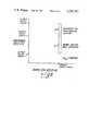
- FIG. 1is an electrical schematic block diagram of the heat pump and refrigeration system in accordance with the present invention.
- the program 40controls the reading of inputs from the thermistor 34, thermostat 36 and the thermistor 60 via the respective A/D converters 42, 43 and 62 and provides for calculating of a digital signal for driving the A/D converter 57 to regulate the speed of the compressor.
- the control meansmaintains the speed of the indoor condenser fan motor 29 to run at its full rated-speed or 100% of speed as shown and described above with respect to FIG. 2.
- the proportional gain amplifier 46, the integrater 48 and the second summer 50provide a control loop with lead compensation for minimizing the error signal from the first summer 44 at steady-state conditions and for cancelling the effect of the lag time in the measured dry bulb temperature reaching the desired condition in response to the change in the compressor speed.
- the digital filter 52has been designed to remove any spurious noise in the measured temperature and/or in the operation of the A/D converters 42 and 43.
Landscapes
- Engineering & Computer Science (AREA)
- Physics & Mathematics (AREA)
- Mechanical Engineering (AREA)
- Thermal Sciences (AREA)
- General Engineering & Computer Science (AREA)
- Chemical & Material Sciences (AREA)
- Combustion & Propulsion (AREA)
- General Physics & Mathematics (AREA)
- Automation & Control Theory (AREA)
- Computer Hardware Design (AREA)
- Air Conditioning Control Device (AREA)
- Central Heating Systems (AREA)
Abstract
Description
Claims (9)
Priority Applications (8)
| Application Number | Priority Date | Filing Date | Title |
|---|---|---|---|
| US06/080,361US4269261A (en) | 1979-09-28 | 1979-09-28 | Microcomputer control for supplemental heating in a heat pump |
| CA000359906ACA1141010A (en) | 1979-09-28 | 1980-09-09 | Microcomputer control for supplemental heating in a heat pump |
| AU62524/80AAU535047B2 (en) | 1979-09-28 | 1980-09-18 | Air conditioning control syst. |
| GB8030897AGB2059647B (en) | 1979-09-28 | 1980-09-25 | Microcomputer control for central heating with night set-back |
| FR8020776AFR2466714A1 (en) | 1979-09-28 | 1980-09-26 | MICROCOMPUTER CONTROL OF THE SUPPLEMENTARY HEATING OF A HEAT PUMP |
| DE19803036291DE3036291A1 (en) | 1979-09-28 | 1980-09-26 | HEATING SYSTEM |
| ES495374AES8106796A1 (en) | 1979-09-28 | 1980-09-26 | A REFRIGERATION SYSTEM TO CONDITION AN ENCLOSURE |
| JP13570980AJPS5656554A (en) | 1979-09-28 | 1980-09-29 | Microocomputer aided control method and system for auxiliary heater in heat pump |
Applications Claiming Priority (1)
| Application Number | Priority Date | Filing Date | Title |
|---|---|---|---|
| US06/080,361US4269261A (en) | 1979-09-28 | 1979-09-28 | Microcomputer control for supplemental heating in a heat pump |
Publications (1)
| Publication Number | Publication Date |
|---|---|
| US4269261Atrue US4269261A (en) | 1981-05-26 |
Family
ID=22156885
Family Applications (1)
| Application Number | Title | Priority Date | Filing Date |
|---|---|---|---|
| US06/080,361Expired - LifetimeUS4269261A (en) | 1979-09-28 | 1979-09-28 | Microcomputer control for supplemental heating in a heat pump |
Country Status (7)
| Country | Link |
|---|---|
| US (1) | US4269261A (en) |
| JP (1) | JPS5656554A (en) |
| AU (1) | AU535047B2 (en) |
| CA (1) | CA1141010A (en) |
| DE (1) | DE3036291A1 (en) |
| ES (1) | ES8106796A1 (en) |
| FR (1) | FR2466714A1 (en) |
Cited By (24)
| Publication number | Priority date | Publication date | Assignee | Title |
|---|---|---|---|---|
| US4364237A (en)* | 1981-02-02 | 1982-12-21 | Borg-Warner Corporation | Microcomputer control for inverter-driven heat pump |
| US4407139A (en)* | 1980-10-13 | 1983-10-04 | Tokyo Shibaura Denki Kabushiki Kaisha | Method for controlling an air conditioning system |
| US4442972A (en)* | 1981-09-14 | 1984-04-17 | Texas Instruments Incorporated | Electrically controlled programmable digital thermostat and method for regulating the operation of multistage heating and cooling systems |
| US4445567A (en)* | 1982-02-26 | 1984-05-01 | Honeywell Inc. | Thermostat for control of an add-on heat pump system |
| US4481788A (en)* | 1981-12-09 | 1984-11-13 | System Homes Company, Ltd. | Water heating system |
| DE3508353A1 (en)* | 1984-03-09 | 1985-09-19 | Hitachi, Ltd., Tokio/Tokyo | METHOD AND DEVICE FOR CONTROLLING AN AIR CONDITIONING SYSTEM WITH A HEAT PUMP |
| US4604872A (en)* | 1984-02-03 | 1986-08-12 | Kabushiki Kaisha Toshiba | Heat pump type air conditioning apparatus having a controlled variable capacity compressor |
| US4627484A (en)* | 1984-01-09 | 1986-12-09 | Visual Information Institute, Inc. | Heat pump control system with defrost cycle monitoring |
| US4627483A (en)* | 1984-01-09 | 1986-12-09 | Visual Information Institute, Inc. | Heat pump control system |
| US4860552A (en)* | 1988-12-23 | 1989-08-29 | Honeywell, Inc. | Heat pump fan control |
| US5259445A (en)* | 1992-07-13 | 1993-11-09 | The Detroit Edison Company | Control for dual heating system including a heat pump and furnace |
| US5438844A (en)* | 1992-07-01 | 1995-08-08 | Gas Research Institute | Microprocessor-based controller |
| US6192700B1 (en)* | 1998-10-12 | 2001-02-27 | Delphi Technologies, Inc. | Air conditioning system for a motor vehicle |
| US6965815B1 (en) | 1987-05-27 | 2005-11-15 | Bilboa Instruments, Inc. | Spa control system |
| US6976052B2 (en) | 1987-05-27 | 2005-12-13 | Balboa Instruments, Inc. | Spa control system |
| US20070035990A1 (en)* | 2005-08-15 | 2007-02-15 | Micron Technology, Inc. | Method and apparatus providing a cross-point memory array using a variable resistance memory cell and capacitance |
| US20070137228A1 (en)* | 2005-09-28 | 2007-06-21 | Gang Li | Heat pump system having a defrost mechanism for low ambient air temperature operation |
| US20070267508A1 (en)* | 2005-12-28 | 2007-11-22 | Honeywell International Inc. | Auxiliary stage control of multistage thermostats |
| US20190049130A1 (en)* | 2017-08-08 | 2019-02-14 | Lennox Industries Inc. | Hybrid tandem compressor system and method of use |
| US10495365B2 (en) | 2017-03-21 | 2019-12-03 | Lennox Industries Inc. | Method and apparatus for balanced fluid distribution in tandem-compressor systems |
| US10655897B2 (en) | 2017-03-21 | 2020-05-19 | Lennox Industries Inc. | Method and apparatus for common pressure and oil equalization in multi-compressor systems |
| US10724753B2 (en) | 2015-12-29 | 2020-07-28 | Carrier Corporation | System and method for operating a variable speed compressor |
| US10731901B2 (en) | 2017-03-21 | 2020-08-04 | Lennox Industries Inc. | Method and apparatus for balanced fluid distribution in multi-compressor systems |
| US10895412B2 (en)* | 2018-07-11 | 2021-01-19 | Mitsubishi Electric Research Laboratories, Inc. | System and method for power optimizing control of multi-zone heat pumps |
Families Citing this family (1)
| Publication number | Priority date | Publication date | Assignee | Title |
|---|---|---|---|---|
| JPH03117844A (en)* | 1989-09-29 | 1991-05-20 | Toshiba Corp | Air conditioner control method |
Citations (4)
| Publication number | Priority date | Publication date | Assignee | Title |
|---|---|---|---|---|
| US3041849A (en)* | 1959-09-25 | 1962-07-03 | Borg Warner | Heat pump systems |
| US3214931A (en)* | 1964-05-25 | 1965-11-02 | Trane Co | Thermostatic control for refrigeration systems |
| US3499297A (en)* | 1969-02-20 | 1970-03-10 | John D Ruff | Variable capacity refrigeration system |
| US4148436A (en)* | 1977-03-30 | 1979-04-10 | Dunham-Bush, Inc. | Solar augmented heat pump system with automatic staging reciprocating compressor |
Family Cites Families (7)
| Publication number | Priority date | Publication date | Assignee | Title |
|---|---|---|---|---|
| US2981479A (en)* | 1959-06-29 | 1961-04-25 | Westinghouse Electric Corp | Air heating systems |
| US3324672A (en)* | 1964-08-31 | 1967-06-13 | Gen Motors Corp | Electrically controlled conditioning system |
| DE2509319A1 (en)* | 1975-03-04 | 1976-09-16 | Bosch Gmbh Robert | Heating pump for circulating heating purposes - condenser is driven by rpm-controlled electric motor |
| DE2705869C2 (en)* | 1977-02-11 | 1979-05-03 | Motorheizung Gmbh, 3000 Hannover | Heat pump heating system |
| DE2711601A1 (en)* | 1977-03-17 | 1978-09-21 | Bosch Gmbh Robert | Control system for water circulation central heating - regulates heating output according to rated value deviation of water circulation temp. |
| DE2745400A1 (en)* | 1977-10-08 | 1979-04-12 | Bosch Gmbh Robert | Central heating control equipment - has computer to compare temp. of solar heater, heat exchanger and heat accumulator and to compare values with that of circulating water |
| JPS5462641A (en)* | 1977-10-11 | 1979-05-19 | Robertshaw Controls Co | Thermostat |
- 1979
- 1979-09-28USUS06/080,361patent/US4269261A/ennot_activeExpired - Lifetime
- 1980
- 1980-09-09CACA000359906Apatent/CA1141010A/ennot_activeExpired
- 1980-09-18AUAU62524/80Apatent/AU535047B2/ennot_activeCeased
- 1980-09-26ESES495374Apatent/ES8106796A1/ennot_activeExpired
- 1980-09-26FRFR8020776Apatent/FR2466714A1/enactiveGranted
- 1980-09-26DEDE19803036291patent/DE3036291A1/ennot_activeCeased
- 1980-09-29JPJP13570980Apatent/JPS5656554A/enactivePending
Patent Citations (4)
| Publication number | Priority date | Publication date | Assignee | Title |
|---|---|---|---|---|
| US3041849A (en)* | 1959-09-25 | 1962-07-03 | Borg Warner | Heat pump systems |
| US3214931A (en)* | 1964-05-25 | 1965-11-02 | Trane Co | Thermostatic control for refrigeration systems |
| US3499297A (en)* | 1969-02-20 | 1970-03-10 | John D Ruff | Variable capacity refrigeration system |
| US4148436A (en)* | 1977-03-30 | 1979-04-10 | Dunham-Bush, Inc. | Solar augmented heat pump system with automatic staging reciprocating compressor |
Cited By (31)
| Publication number | Priority date | Publication date | Assignee | Title |
|---|---|---|---|---|
| US4407139A (en)* | 1980-10-13 | 1983-10-04 | Tokyo Shibaura Denki Kabushiki Kaisha | Method for controlling an air conditioning system |
| US4364237A (en)* | 1981-02-02 | 1982-12-21 | Borg-Warner Corporation | Microcomputer control for inverter-driven heat pump |
| US4442972A (en)* | 1981-09-14 | 1984-04-17 | Texas Instruments Incorporated | Electrically controlled programmable digital thermostat and method for regulating the operation of multistage heating and cooling systems |
| US4481788A (en)* | 1981-12-09 | 1984-11-13 | System Homes Company, Ltd. | Water heating system |
| US4445567A (en)* | 1982-02-26 | 1984-05-01 | Honeywell Inc. | Thermostat for control of an add-on heat pump system |
| US4627484A (en)* | 1984-01-09 | 1986-12-09 | Visual Information Institute, Inc. | Heat pump control system with defrost cycle monitoring |
| US4627483A (en)* | 1984-01-09 | 1986-12-09 | Visual Information Institute, Inc. | Heat pump control system |
| US4604872A (en)* | 1984-02-03 | 1986-08-12 | Kabushiki Kaisha Toshiba | Heat pump type air conditioning apparatus having a controlled variable capacity compressor |
| US4603556A (en)* | 1984-03-09 | 1986-08-05 | Hitachi, Ltd. | Control method and apparatus for an air conditioner using a heat pump |
| DE3508353A1 (en)* | 1984-03-09 | 1985-09-19 | Hitachi, Ltd., Tokio/Tokyo | METHOD AND DEVICE FOR CONTROLLING AN AIR CONDITIONING SYSTEM WITH A HEAT PUMP |
| US6976052B2 (en) | 1987-05-27 | 2005-12-13 | Balboa Instruments, Inc. | Spa control system |
| US6965815B1 (en) | 1987-05-27 | 2005-11-15 | Bilboa Instruments, Inc. | Spa control system |
| US4860552A (en)* | 1988-12-23 | 1989-08-29 | Honeywell, Inc. | Heat pump fan control |
| US5438844A (en)* | 1992-07-01 | 1995-08-08 | Gas Research Institute | Microprocessor-based controller |
| US5628199A (en)* | 1992-07-01 | 1997-05-13 | Gas Research Institute | Microprocessor-based controller |
| US5259445A (en)* | 1992-07-13 | 1993-11-09 | The Detroit Edison Company | Control for dual heating system including a heat pump and furnace |
| US6192700B1 (en)* | 1998-10-12 | 2001-02-27 | Delphi Technologies, Inc. | Air conditioning system for a motor vehicle |
| US20070035990A1 (en)* | 2005-08-15 | 2007-02-15 | Micron Technology, Inc. | Method and apparatus providing a cross-point memory array using a variable resistance memory cell and capacitance |
| US20070137228A1 (en)* | 2005-09-28 | 2007-06-21 | Gang Li | Heat pump system having a defrost mechanism for low ambient air temperature operation |
| US20070267508A1 (en)* | 2005-12-28 | 2007-11-22 | Honeywell International Inc. | Auxiliary stage control of multistage thermostats |
| US7644869B2 (en) | 2005-12-28 | 2010-01-12 | Honeywell International Inc. | Auxiliary stage control of multistage thermostats |
| US10724753B2 (en) | 2015-12-29 | 2020-07-28 | Carrier Corporation | System and method for operating a variable speed compressor |
| US10495365B2 (en) | 2017-03-21 | 2019-12-03 | Lennox Industries Inc. | Method and apparatus for balanced fluid distribution in tandem-compressor systems |
| US10655897B2 (en) | 2017-03-21 | 2020-05-19 | Lennox Industries Inc. | Method and apparatus for common pressure and oil equalization in multi-compressor systems |
| US10731901B2 (en) | 2017-03-21 | 2020-08-04 | Lennox Industries Inc. | Method and apparatus for balanced fluid distribution in multi-compressor systems |
| US11274862B2 (en) | 2017-03-21 | 2022-03-15 | Lennox Industries Inc. | Method and apparatus for balanced fluid distribution in multi-compressor systems |
| US11415347B2 (en) | 2017-03-21 | 2022-08-16 | Lennox Industries Inc. | Method and apparatus for balanced fluid distribution in tandem-compressor systems |
| US10465937B2 (en)* | 2017-08-08 | 2019-11-05 | Lennox Industries Inc. | Hybrid tandem compressor system and method of use |
| US20190049130A1 (en)* | 2017-08-08 | 2019-02-14 | Lennox Industries Inc. | Hybrid tandem compressor system and method of use |
| US10935274B2 (en) | 2017-08-08 | 2021-03-02 | Lennox Industries Inc. | Hybrid tandem compressor system and method of use |
| US10895412B2 (en)* | 2018-07-11 | 2021-01-19 | Mitsubishi Electric Research Laboratories, Inc. | System and method for power optimizing control of multi-zone heat pumps |
Also Published As
| Publication number | Publication date |
|---|---|
| AU6252480A (en) | 1981-04-09 |
| FR2466714B1 (en) | 1983-06-17 |
| ES495374A0 (en) | 1981-08-01 |
| JPS5656554A (en) | 1981-05-18 |
| FR2466714A1 (en) | 1981-04-10 |
| ES8106796A1 (en) | 1981-08-01 |
| AU535047B2 (en) | 1984-03-01 |
| CA1141010A (en) | 1983-02-08 |
| DE3036291A1 (en) | 1981-04-16 |
Similar Documents
| Publication | Publication Date | Title |
|---|---|---|
| US4269261A (en) | Microcomputer control for supplemental heating in a heat pump | |
| US4364237A (en) | Microcomputer control for inverter-driven heat pump | |
| US4257238A (en) | Microcomputer control for an inverter-driven heat pump | |
| US4353409A (en) | Apparatus and method for controlling a variable air volume temperature conditioning system | |
| US5319943A (en) | Frost/defrost control system for heat pump | |
| US4393662A (en) | Control system for refrigeration or air conditioning installation | |
| US4748822A (en) | Speed control of a variable speed air conditioning system | |
| US4270362A (en) | Control system for an air conditioning system having supplementary, ambient derived cooling | |
| US4265299A (en) | Heat pump control system | |
| US5052186A (en) | Control of outdoor air source water heating using variable-speed heat pump | |
| CA1164970A (en) | Microprocessor discharge temperature air controller for multi-stage heating and/or cooling apparatus and outdoor air usage controller | |
| US9863681B2 (en) | Expansion valve control system and method for air conditioning apparatus | |
| JPH0355736B2 (en) | ||
| JPS60200037A (en) | Controller for temperature regulating system and method thereof | |
| US10941951B2 (en) | Systems and methods for temperature and humidity control | |
| IL107660A (en) | Control system for heat pump/air-conditioning system for improved cyclic performance | |
| US20150338111A1 (en) | Variable Speed Outdoor Fan Control | |
| US10612826B2 (en) | Systems and methods for electronic expansion valve control | |
| US20170030621A1 (en) | Low ambient cooling scheme and control | |
| JPS6150221B2 (en) | ||
| US6089464A (en) | Thermal dynamic balancer | |
| US20050087616A1 (en) | Thermal balance temperature control system | |
| GB2059646A (en) | Microcomputer control for supplemental heating in a heat pump | |
| JPH01222137A (en) | air conditioner | |
| US4214626A (en) | Rejected heat air conditioning control system |
Legal Events
| Date | Code | Title | Description |
|---|---|---|---|
| STCF | Information on status: patent grant | Free format text:PATENTED CASE | |
| AS | Assignment | Owner name:YORK INTERNATIONAL CORPORATION, 631 SOUTH RICHLAN Free format text:ASSIGNMENT OF ASSIGNORS INTEREST. EFFECTIVE;ASSIGNOR:BORG-WARNER CORPORATION;REEL/FRAME:004676/0360 Effective date:19860609 | |
| AS | Assignment | Owner name:CANADIAN IMPERIAL BANK OF COMMERCE Free format text:SECURITY INTEREST;ASSIGNOR:YORK INTERNATIONAL CORPORATION;REEL/FRAME:005156/0705 Effective date:19881215 | |
| AS | Assignment | Owner name:CANADIAN IMPERIAL BANK OF COMMERCE Free format text:SECURITY INTEREST;ASSIGNOR:YORK OPERATING COMPANY, F/K/A YORK INTERNATIONAL CORPORATION A DE CORP.;REEL/FRAME:005994/0916 Effective date:19911009 | |
| AS | Assignment | Owner name:CANADIAN IMPERIAL BANK OF COMMERCE Free format text:SECURITY INTEREST;ASSIGNOR:YORK INTERNATIONAL CORPORATION (F/K/A YORK OPERATING COMPANY);REEL/FRAME:006007/0123 Effective date:19911231 | |
| AS | Assignment | Owner name:CANADIAN IMPERIAL BANK OF COMMERCE Free format text:RELEASED BY SECURED PARTY;ASSIGNOR:YORK INTERNATIONAL CORPORATION, A DE CORP.;REEL/FRAME:006194/0182 Effective date:19920630 |