US4264345A - Filter housing - Google Patents
Filter housingDownload PDFInfo
- Publication number
- US4264345A US4264345AUS06/075,173US7517379AUS4264345AUS 4264345 AUS4264345 AUS 4264345AUS 7517379 AUS7517379 AUS 7517379AUS 4264345 AUS4264345 AUS 4264345A
- Authority
- US
- United States
- Prior art keywords
- housing
- frame
- supporting member
- filter
- levers
- Prior art date
- Legal status (The legal status is an assumption and is not a legal conclusion. Google has not performed a legal analysis and makes no representation as to the accuracy of the status listed.)
- Expired - Lifetime
Links
- 239000007789gasSubstances0.000claimsdescription65
- 238000007789sealingMethods0.000claimsdescription8
- 230000000694effectsEffects0.000claimsdescription2
- 238000009434installationMethods0.000claims2
- 230000003319supportive effectEffects0.000claims2
- 238000004140cleaningMethods0.000description8
- 238000001914filtrationMethods0.000description4
- 239000011236particulate materialSubstances0.000description4
- 238000010276constructionMethods0.000description3
- 238000011010flushing procedureMethods0.000description3
- 230000002950deficientEffects0.000description2
- 239000002184metalSubstances0.000description2
- 238000000926separation methodMethods0.000description2
- 238000011044inertial separationMethods0.000description1
- 239000000463materialSubstances0.000description1
- 238000005192partitionMethods0.000description1
- 230000000737periodic effectEffects0.000description1
- 230000000717retained effectEffects0.000description1
- 239000011435rockSubstances0.000description1
- 239000007787solidSubstances0.000description1
- 238000011144upstream manufacturingMethods0.000description1
Images


Classifications
- B—PERFORMING OPERATIONS; TRANSPORTING
- B01—PHYSICAL OR CHEMICAL PROCESSES OR APPARATUS IN GENERAL
- B01D—SEPARATION
- B01D46/00—Filters or filtering processes specially modified for separating dispersed particles from gases or vapours
- B01D46/02—Particle separators, e.g. dust precipitators, having hollow filters made of flexible material
- B01D46/04—Cleaning filters
- B—PERFORMING OPERATIONS; TRANSPORTING
- B01—PHYSICAL OR CHEMICAL PROCESSES OR APPARATUS IN GENERAL
- B01D—SEPARATION
- B01D46/00—Filters or filtering processes specially modified for separating dispersed particles from gases or vapours
- B01D46/0002—Casings; Housings; Frame constructions
- B01D46/0004—Details of removable closures, lids, caps or filter heads
- B—PERFORMING OPERATIONS; TRANSPORTING
- B01—PHYSICAL OR CHEMICAL PROCESSES OR APPARATUS IN GENERAL
- B01D—SEPARATION
- B01D46/00—Filters or filtering processes specially modified for separating dispersed particles from gases or vapours
- B01D46/56—Filters or filtering processes specially modified for separating dispersed particles from gases or vapours with multiple filtering elements, characterised by their mutual disposition
- B01D46/58—Filters or filtering processes specially modified for separating dispersed particles from gases or vapours with multiple filtering elements, characterised by their mutual disposition connected in parallel
- B—PERFORMING OPERATIONS; TRANSPORTING
- B01—PHYSICAL OR CHEMICAL PROCESSES OR APPARATUS IN GENERAL
- B01D—SEPARATION
- B01D46/00—Filters or filtering processes specially modified for separating dispersed particles from gases or vapours
- B01D46/66—Regeneration of the filtering material or filter elements inside the filter
- B01D46/70—Regeneration of the filtering material or filter elements inside the filter by acting counter-currently on the filtering surface, e.g. by flushing on the non-cake side of the filter
- B01D46/71—Regeneration of the filtering material or filter elements inside the filter by acting counter-currently on the filtering surface, e.g. by flushing on the non-cake side of the filter with pressurised gas, e.g. pulsed air
- B—PERFORMING OPERATIONS; TRANSPORTING
- B01—PHYSICAL OR CHEMICAL PROCESSES OR APPARATUS IN GENERAL
- B01D—SEPARATION
- B01D50/00—Combinations of methods or devices for separating particles from gases or vapours
- B01D50/20—Combinations of devices covered by groups B01D45/00 and B01D46/00
- B—PERFORMING OPERATIONS; TRANSPORTING
- B01—PHYSICAL OR CHEMICAL PROCESSES OR APPARATUS IN GENERAL
- B01D—SEPARATION
- B01D2201/00—Details relating to filtering apparatus
- B01D2201/31—Other construction details
- B01D2201/313—Means for protecting the filter from the incoming fluid, e.g. shields
- B—PERFORMING OPERATIONS; TRANSPORTING
- B01—PHYSICAL OR CHEMICAL PROCESSES OR APPARATUS IN GENERAL
- B01D—SEPARATION
- B01D2265/00—Casings, housings or mounting for filters specially adapted for separating dispersed particles from gases or vapours
- B01D2265/02—Non-permanent measures for connecting different parts of the filter
- B01D2265/028—Snap, latch or clip connecting means
Definitions
- the present inventionrelates to gas separation devices and in particular to a bag house arrangement for filtering particulate material out of a dirty gas stream.
- a plurality of tubular filtersare supported within the housing of the bag house by an apertured plate or tube sheet extending across the housing.
- the tube sheetis welded or otherwise appropriately secured to the walls of the housing and divides it into a dirty gas chamber and a clean gas plenum interconnected in flow-through communication by the apertures in the plate; and, a filter is provided for each aperture to filter the gas stream as it flows from the dirty gas chamber into the clean gas plenum.
- the present inventionrelates to gas separation devices and in particular to a bag house having one or more removable filter units carrying a plurality of filter elements for filtering out particulate solids in a dirty gas stream.
- Each of the filter unitsincludes a flow-through filter media support member releasably secured in the housing of the bag house to divide the housing into a dirty gas chamber and a clean gas chamber.
- the support membersare carried within the housing by a frame extending across the interior of the housing and are releasably secured to the frame by a plurality of clamps which can be manipulated by a workman through an access door in the wall of the housing.
- a workmansimply aligns the support member of the filter unit along the frame and engages the clamps to secure the support member in sealing engagement with the frame.
- the clampsare disengaged from the support members and the unit is withdrawn from the housing through the access door in the wall of the housing.
- FIG. 1is a front elevational view of a bag house embodying the invention
- FIG. 2is a plan sectional view, partially in section, taken generally along line 2--2 in FIG. 1;
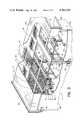
- FIG. 3is an isometric view, partially in section, of the bag house shown in FIG. 1;
- FIG. 4is a vertical cross-sectional view taken generally along line 4--4 in FIG. 2;
- FIG. 5is a plan view of one of the support members removed from the bag house shown in FIGS. 1-4;
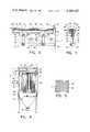
- FIG. 6is a side elevational view, partially in section, showing the clamping arrangement provided to secure the filter unit in the bag house shown in FIGS. 1-4;
- FIG. 7is an end elevational view, partially in section, of the clamping arrangement shown in FIG. 6;
- FIG. 8is an isometric view, partially in section, of another bag house embodying the invention.
- FIG. 9is a front elevational view, partially in section, of the bag house shown in FIG. 8;
- FIG. 10is a side elevational view, partially in section, showing the clamping arrangement provided to secure the filter unit in the bag house shown in FIGS. 8 and 9;
- FIG. 11is an end elevational view, partially in section, of the clamping arrangement shown in FIG. 10.
- the gas cleaning system embodying the inventionincludes a filter housing or bag house 1 having a dirty gas inlet 2 and a clean gas outlet 3.
- the housingincludes a transversely extending support frame 4 having a series of opposing parallel channel members 5 and 6 adapted to carry a plurality of removable filter units 7 which divide the housing into a dirty gas cleaning chamber 8 and a clean gas take-off chamber or plenum 9.
- Each of the filter units 7includes a filter supporting member or tube sheet 10 which carries a plurality of tubular filters 11 and is releasably inserted between the opposing channel members 5 and 6.
- this arrangementaccommodates rapid and convenient removal of the filter supporting members from the housing for repair or replacement of the tubular filters. Thereafter, the supporting members 10 can be easily reinserted and secured between the channel members by clamping linkages 12 mounted on the frame 4.
- dirty gasesare directed through the inlet 2 into the dirty gas chamber 8 where they are initially directed downwardly and outwardly by the baffle plate 13 to establish a substantially uniform flow of gases within the chamber. These gases in turn flow upwardly through the filters 11 and out of the housing through the plenum 9 and the clean gas outlet 3.
- the housingincludes a valve controlled reverse flow flushing arrangement 16.
- the flushing arrangementincludes a plurality of air pulsing pipes 17 having orifaces or nozzles 18 aligned above each of the filters 11 adapted to inject jets or pulses of air into the filters during filter cleaning operations.
- the housing 1is preferably of a welded sheet metal construction having spaced opposed side walls 19 and 20 interconnected by spaced opposed side walls 21 and 22, a roof or top 23, and hoppers 14.
- a rectangular baffle plate 13is provided adjacent the dirty gas inlet 2 within the dirty gas chamber 8 to direct and stabilize the entrant flow of dirty gases into the chamber.
- the baffle plate 13,which is generally vertically coextensive with the filters 11 and is substantially centered along the breadth of the housing parallel to the cross-section of the inlet 2, is suppported by posts 24 securing it in spaced relation to the wall 20. This arrangement disperses the entrant flow throughout the dirty gas chamber while also effecting inertial separation of particulate materials from the gases resulting from the relatively abrupt redirection of the flow as it enters the chamber.
- each of the opposing channel members 5 and 6extends across the interior of the housing and is secured to the wall 19 and a closure panel or beam 25 secured along the opposite wall 20.
- the channel memberswhich are interconnected by lateral sealing strips or plates 26 to define a series of adjacent rectilinear openings in the support frame 4, are positioned along the width of the housing to provide a series of opposing trackways or slots 27 and 28 which are adapted to slidingly receive and carry a pair of adjacent support members 10 between each pair of opposing channel members.
- each supporting member 10is aligned to cover an associated opening in the frame to form a limiting partition separating the dirty gas chamber from the clean gas plenum.
- the support membersengage the marginal edges of the frame openings on the upstream side of the frame such that the dirty gases urge the support members into sealing engagement with the frame as a result of the gas pressure drop between the dirty gas chamber and the clean gas plenum.
- the filter supporting members 10are secured to the frame 4 by clamping linkages 12 which clamp the marginal edges of the supporting members to the channel members.
- Each linkage 12includes a pair of lifting levers 29 having protruding lugs 30 at one end and being pivotally secured by bolts or pins 31 to flanges 32 and 33 depending from the channel members.
- the levers 29are pivotally interconnected by a rigid operating bar or link 34 which can be easily manipulated by a workman through the openings 35 in the wall 19 covered by the doors 36, it being noted that the doors are preferably hung on the wall by hinges 37 or the like and secured in the closed position by conventional latches 38.
- a workmanfirst pulls the operating bars 34 outwardly into the disengaged position generally illustrated by the dotted lines in FIG. 6.
- the supporting membersare slidably carried on the lower flanges of the channel members such that the filter units can be conveniently withdrawn from the housing through the openings 35.
- a pair of replacement unitsare then slid into place between the opposing channel members and the operating bars 34 are pushed back into the housing. This rotates the levers 29 so that the protruding lugs 30 lift the supporting members 10 into sealing engagement with the marginal edges of the respective rectilinear openings in the frame through the compressible gaskets 39 surrounding the periphery of each supporting member.
- FIGS. 8-11show another embodiment of the invention which is particularly suited for lower volume air filtration requirements such as those required for small rock drills, pneumatic conveying systems used to load comminuted bulk into railway hopper cars, grain silos, and related applications.
- This embodimentwhich is adapted to use the same modular filter unit 7 as the foregoing gas cleaning arrangement, includes an essentially square filter housing 50 having a dirty gas inlet 51 and a clean gas outlet 52.
- the modular filter unit 7divides the housing 50 into a dirty gas cleaning chamber 53 and a plenum or clean gas take-off chamber 54.
- the housing 50is preferably of a welded sheet metal construction including spaced opposed walls 59 and 60 interconnected by spaced opposed walls 61 and 62, a top or cover 63, and the hopper 56.
- the wall 60includes an opening 64 covered by a removable door or panel 65 secured by screws or the like to the wall 60.
- angle members 66 and 67are secured to the opposing walls 61 and 62 to define a pair of opposing slots or trackways 68 and 69, and, angle members 70 are secured to the opposing walls 59 and 60 in alignment with the members 66 and 67 to form a sealing surface about the interior periphery of the housing.
- the opposing trackways 68 and 69slidably receive and carry the supporting member 10 to support the filter unit 7 within the housing, and clamping levers 71 pivotally connected to the walls 61 and 62 by pins or bolts 72 secure the unit within the housing.
- the supporting member 10when installing a new or replacement unit in the housing 50, the supporting member 10 is first slid into place in the trackways 68 and 69. This rotates the levers 71 into the position generally indicated by the dotted lines in FIG. 10. The levers 71 are then rotated to the clamping position to lift the supporting member 10 into sealing engagement with the angle members 66 and 70 through the gasket 39. Thereafter, the door 65, which retains the levers in the clamping position, is resecured and the system is put back in operation.
Landscapes
- Chemical & Material Sciences (AREA)
- Chemical Kinetics & Catalysis (AREA)
- Filtering Of Dispersed Particles In Gases (AREA)
Abstract
Description
Claims (6)
Priority Applications (1)
| Application Number | Priority Date | Filing Date | Title |
|---|---|---|---|
| US06/075,173US4264345A (en) | 1979-09-12 | 1979-09-12 | Filter housing |
Applications Claiming Priority (1)
| Application Number | Priority Date | Filing Date | Title |
|---|---|---|---|
| US06/075,173US4264345A (en) | 1979-09-12 | 1979-09-12 | Filter housing |
Publications (1)
| Publication Number | Publication Date |
|---|---|
| US4264345Atrue US4264345A (en) | 1981-04-28 |
Family
ID=22124033
Family Applications (1)
| Application Number | Title | Priority Date | Filing Date |
|---|---|---|---|
| US06/075,173Expired - LifetimeUS4264345A (en) | 1979-09-12 | 1979-09-12 | Filter housing |
Country Status (1)
| Country | Link |
|---|---|
| US (1) | US4264345A (en) |
Cited By (45)
| Publication number | Priority date | Publication date | Assignee | Title |
|---|---|---|---|---|
| US4322231A (en)* | 1980-06-16 | 1982-03-30 | Farr Company | Filter element locking mechanism |
| US4323376A (en)* | 1980-09-02 | 1982-04-06 | Rosenquest Arthur P | Dust collector with quick release filter support system for use in dust collectors |
| FR2513539A1 (en)* | 1981-09-28 | 1983-04-01 | Neu Ets | Vertical bag filter - employs framework for internal support against external pressure |
| US4435197A (en) | 1982-04-09 | 1984-03-06 | The Bahnson Company | Baghouse filter |
| US4445912A (en)* | 1982-02-04 | 1984-05-01 | The Mike Volk Co., Inc. | Effluent air filtration apparatus |
| US4525184A (en)* | 1983-05-20 | 1985-06-25 | Electric Power Research Institute, Inc. | Vertically tiered particle filtering apparatus |
| US4632681A (en)* | 1985-04-25 | 1986-12-30 | Wheelabrator Corporation Of Canada, Ltd. | Locking apparatus for filter elements |
| US4865627A (en)* | 1987-10-30 | 1989-09-12 | Shell Oil Company | Method and apparatus for separating fine particulates from a mixture of fine particulates and gas |
| US4969937A (en)* | 1989-05-30 | 1990-11-13 | Electric Power Research Institute | Vertically tiered particle filtering apparatus |
| US5035799A (en)* | 1989-08-21 | 1991-07-30 | Clear Flow, Inc. | Filter assembly |
| US5053063A (en)* | 1988-08-18 | 1991-10-01 | Sisk David E | Dust filtering and collection system |
| US5073259A (en)* | 1989-07-11 | 1991-12-17 | Solimar Yachts | Manhole mounted filtering system for self-loading semi-trailer |
| USRE34055E (en)* | 1983-05-20 | 1992-09-08 | Electric Power Research Institute, Inc. | Vertically tiered particle filtering apparatus |
| US5395409A (en)* | 1994-02-03 | 1995-03-07 | Dustex Corporation | Dust collecting apparatus having reverse pulse filter cleaning capability |
| BE1008278A3 (en)* | 1994-01-25 | 1996-03-05 | Vangroenweghe Lucien | Air filter with suspended filter sleeves |
| US5599364A (en)* | 1994-11-14 | 1997-02-04 | Hawkins; Charles | Filter locking/support system for dust collectors |
| US5656049A (en)* | 1995-03-23 | 1997-08-12 | Helical Dynamics, Inc. | Separator suspension system for a modular air handling system |
| WO1997004852A3 (en)* | 1995-07-27 | 1997-12-04 | Pall Corp | Hybrid filter system and method for filtering process fluid |
| EP0875274A3 (en)* | 1997-04-08 | 1999-01-20 | GRAF-EPE GmbH | Exhaust gas cleaning and process for conducting such a gas cleaning |
| US6099612A (en)* | 1998-09-04 | 2000-08-08 | Filtration Group, Inc. | Side access filter support and sealing system |
| US6146433A (en)* | 1999-05-11 | 2000-11-14 | Venturedyne, Ltd. | Internal air baffle |
| US6444005B1 (en) | 2000-08-14 | 2002-09-03 | Venturedyne, Ltd. | Filter engagement device |
| US6613115B2 (en)* | 2000-08-12 | 2003-09-02 | Stephen H. Moore | Cartridge dust collector |
| US6626970B2 (en) | 2000-12-29 | 2003-09-30 | Air Cure, Inc. | Wire filter cage |
| US20030200733A1 (en)* | 2002-04-30 | 2003-10-30 | Jung Bong Kyu | Dust collector with assembly of cylindrical and hexahedral bag filter |
| US20050155333A1 (en)* | 2003-05-08 | 2005-07-21 | Markus Exner | Cleaning device for a bundle of tubular filter elements designed with one end open, preferably of an industrial dust filter |
| US20050183404A1 (en)* | 2000-12-29 | 2005-08-25 | Howard Pipkorn | Wire filter cage |
| US20060016767A1 (en)* | 2004-07-23 | 2006-01-26 | I.S.C. Environmental, Inc. | Fluid filter system and related method |
| US20060207230A1 (en)* | 2003-03-17 | 2006-09-21 | Demarco Maxvac Corporation | Vacuum loader with filter doors |
| US20070271885A1 (en)* | 2006-05-29 | 2007-11-29 | Mann & Hummel Gmbh | Axial flow filter element |
| EP1870444A3 (en)* | 2006-06-20 | 2008-02-20 | Walter Kuntschar | Method for cleaning gases from a woodgas powered vehicle and filter therefore |
| WO2009044265A3 (en)* | 2007-10-02 | 2009-08-06 | Rd42 Technologies S R L A Soci | Bag filter and method for its construction |
| EP2263775A1 (en)* | 2009-06-15 | 2010-12-22 | Edwin Eisenegger | Hose filter device |
| US20110030558A1 (en)* | 2008-02-05 | 2011-02-10 | Raether Thomas D | Dust collector, filtration arrangment, and methods |
| US8226738B2 (en) | 2010-05-17 | 2012-07-24 | Air-Cure Incorporated | Wire filter cage locking mechanism |
| US20130180221A1 (en)* | 2005-09-09 | 2013-07-18 | Dexwet Usa Llc | Filter module |
| US8702849B2 (en) | 2011-06-03 | 2014-04-22 | Matson, Inc. | Dust screen and method for dry bulk storage units |
| US9849417B2 (en) | 2014-10-22 | 2017-12-26 | Aireau Qualite Controle Inc. | Dust collector having vertical filters and a filter carriage |
| RU2697689C1 (en)* | 2018-09-19 | 2019-08-16 | Артем Сергеевич Ткаченко | Sleeve / cartridge filter |
| US10626592B2 (en) | 2008-01-16 | 2020-04-21 | Contech Engineered Solutions LLC | Filter for removing sediment from water |
| US20210245078A1 (en)* | 2018-06-13 | 2021-08-12 | Cargill, Incorporated | Liquid discharge filter and its use |
| US20210339182A1 (en)* | 2018-10-26 | 2021-11-04 | Zhejiang Hongsheng New Material Technology Group Co., Ltd | Modularized dust collector system and control method thereof |
| US20210346824A1 (en)* | 2020-04-13 | 2021-11-11 | Evoqua Water Techhnologies LLC | Regenerative Media Filtration Apparatus Improvements |
| US20240001274A1 (en)* | 2020-11-23 | 2024-01-04 | Zhejiang Hongsheng New Material Technology Group Co., Ltd | Modular rapping dust remover |
| US12370481B1 (en)* | 2014-03-18 | 2025-07-29 | Best Box, Llc | Filter cabinet for furnace systems |
Citations (12)
| Publication number | Priority date | Publication date | Assignee | Title |
|---|---|---|---|---|
| US3063224A (en)* | 1961-01-27 | 1962-11-13 | American Air Filter Co | Latch assembly for filter housing |
| US3360910A (en)* | 1966-05-31 | 1968-01-02 | Envirco Inc | Filter framing system |
| US3486310A (en)* | 1967-06-22 | 1969-12-30 | Boliden Ab | Bag filter system |
| US3513638A (en)* | 1968-03-08 | 1970-05-26 | Henry T Young | Filter |
| US3581478A (en)* | 1968-02-21 | 1971-06-01 | Peter W Smith | Filter and filter assembly |
| US3630008A (en)* | 1969-10-23 | 1971-12-28 | American Air Filter Co | Filter cell sealing and retaining arrangement |
| US3726066A (en)* | 1970-12-14 | 1973-04-10 | Wheelabrator Frye Inc | Dust collector |
| US3788046A (en)* | 1970-06-12 | 1974-01-29 | Slick Corp | Apparatus for filtering gases having a movable filter bag unit |
| US3837150A (en)* | 1972-12-08 | 1974-09-24 | Torit Corp | Filtering apparatus with pneumatic intermittent cleaning |
| US3951627A (en)* | 1975-01-09 | 1976-04-20 | Pneumafil Corporation | Air filtering apparatus |
| FR2396580A1 (en)* | 1977-07-07 | 1979-02-02 | France Etat | DEVICE FOR BLOCKING A REMOVABLE ELEMENT FOR AIR FILTRATION |
| US4158554A (en)* | 1977-02-07 | 1979-06-19 | Standard Havens, Inc. | Apparatus for filtering particulate-laden gases |
- 1979
- 1979-09-12USUS06/075,173patent/US4264345A/ennot_activeExpired - Lifetime
Patent Citations (12)
| Publication number | Priority date | Publication date | Assignee | Title |
|---|---|---|---|---|
| US3063224A (en)* | 1961-01-27 | 1962-11-13 | American Air Filter Co | Latch assembly for filter housing |
| US3360910A (en)* | 1966-05-31 | 1968-01-02 | Envirco Inc | Filter framing system |
| US3486310A (en)* | 1967-06-22 | 1969-12-30 | Boliden Ab | Bag filter system |
| US3581478A (en)* | 1968-02-21 | 1971-06-01 | Peter W Smith | Filter and filter assembly |
| US3513638A (en)* | 1968-03-08 | 1970-05-26 | Henry T Young | Filter |
| US3630008A (en)* | 1969-10-23 | 1971-12-28 | American Air Filter Co | Filter cell sealing and retaining arrangement |
| US3788046A (en)* | 1970-06-12 | 1974-01-29 | Slick Corp | Apparatus for filtering gases having a movable filter bag unit |
| US3726066A (en)* | 1970-12-14 | 1973-04-10 | Wheelabrator Frye Inc | Dust collector |
| US3837150A (en)* | 1972-12-08 | 1974-09-24 | Torit Corp | Filtering apparatus with pneumatic intermittent cleaning |
| US3951627A (en)* | 1975-01-09 | 1976-04-20 | Pneumafil Corporation | Air filtering apparatus |
| US4158554A (en)* | 1977-02-07 | 1979-06-19 | Standard Havens, Inc. | Apparatus for filtering particulate-laden gases |
| FR2396580A1 (en)* | 1977-07-07 | 1979-02-02 | France Etat | DEVICE FOR BLOCKING A REMOVABLE ELEMENT FOR AIR FILTRATION |
Cited By (63)
| Publication number | Priority date | Publication date | Assignee | Title |
|---|---|---|---|---|
| US4322231A (en)* | 1980-06-16 | 1982-03-30 | Farr Company | Filter element locking mechanism |
| US4323376A (en)* | 1980-09-02 | 1982-04-06 | Rosenquest Arthur P | Dust collector with quick release filter support system for use in dust collectors |
| FR2513539A1 (en)* | 1981-09-28 | 1983-04-01 | Neu Ets | Vertical bag filter - employs framework for internal support against external pressure |
| US4445912A (en)* | 1982-02-04 | 1984-05-01 | The Mike Volk Co., Inc. | Effluent air filtration apparatus |
| US4435197A (en) | 1982-04-09 | 1984-03-06 | The Bahnson Company | Baghouse filter |
| EP0091673A3 (en)* | 1982-04-09 | 1984-08-22 | The Bahnson Company | Baghouse filter assembly |
| US4525184A (en)* | 1983-05-20 | 1985-06-25 | Electric Power Research Institute, Inc. | Vertically tiered particle filtering apparatus |
| USRE34055E (en)* | 1983-05-20 | 1992-09-08 | Electric Power Research Institute, Inc. | Vertically tiered particle filtering apparatus |
| US4632681A (en)* | 1985-04-25 | 1986-12-30 | Wheelabrator Corporation Of Canada, Ltd. | Locking apparatus for filter elements |
| US4865627A (en)* | 1987-10-30 | 1989-09-12 | Shell Oil Company | Method and apparatus for separating fine particulates from a mixture of fine particulates and gas |
| US5053063A (en)* | 1988-08-18 | 1991-10-01 | Sisk David E | Dust filtering and collection system |
| US4969937A (en)* | 1989-05-30 | 1990-11-13 | Electric Power Research Institute | Vertically tiered particle filtering apparatus |
| US5073259A (en)* | 1989-07-11 | 1991-12-17 | Solimar Yachts | Manhole mounted filtering system for self-loading semi-trailer |
| US5035799A (en)* | 1989-08-21 | 1991-07-30 | Clear Flow, Inc. | Filter assembly |
| BE1008278A3 (en)* | 1994-01-25 | 1996-03-05 | Vangroenweghe Lucien | Air filter with suspended filter sleeves |
| US5395409A (en)* | 1994-02-03 | 1995-03-07 | Dustex Corporation | Dust collecting apparatus having reverse pulse filter cleaning capability |
| US5599364A (en)* | 1994-11-14 | 1997-02-04 | Hawkins; Charles | Filter locking/support system for dust collectors |
| US5656049A (en)* | 1995-03-23 | 1997-08-12 | Helical Dynamics, Inc. | Separator suspension system for a modular air handling system |
| WO1997004852A3 (en)* | 1995-07-27 | 1997-12-04 | Pall Corp | Hybrid filter system and method for filtering process fluid |
| US5766486A (en)* | 1995-07-27 | 1998-06-16 | Pall Corporation | Hybrid filter system and method for filtering process fluid |
| EP0875274A3 (en)* | 1997-04-08 | 1999-01-20 | GRAF-EPE GmbH | Exhaust gas cleaning and process for conducting such a gas cleaning |
| US6099612A (en)* | 1998-09-04 | 2000-08-08 | Filtration Group, Inc. | Side access filter support and sealing system |
| US6146433A (en)* | 1999-05-11 | 2000-11-14 | Venturedyne, Ltd. | Internal air baffle |
| US6613115B2 (en)* | 2000-08-12 | 2003-09-02 | Stephen H. Moore | Cartridge dust collector |
| US6444005B1 (en) | 2000-08-14 | 2002-09-03 | Venturedyne, Ltd. | Filter engagement device |
| US20050034436A1 (en)* | 2000-12-29 | 2005-02-17 | Air Cure, Inc. | Wire filter cage |
| US7371267B2 (en) | 2000-12-29 | 2008-05-13 | Air Cure, Inc. | Wire filter cage |
| US20040134170A1 (en)* | 2000-12-29 | 2004-07-15 | Air Cure, Inc. | Wire filter cage |
| US6790250B2 (en) | 2000-12-29 | 2004-09-14 | Air Cure, Inc. | Wire filter cage |
| US6626970B2 (en) | 2000-12-29 | 2003-09-30 | Air Cure, Inc. | Wire filter cage |
| US6905529B2 (en)* | 2000-12-29 | 2005-06-14 | Air Cure, Inc. | Wire Filter cage |
| US20050183404A1 (en)* | 2000-12-29 | 2005-08-25 | Howard Pipkorn | Wire filter cage |
| US6786946B2 (en)* | 2002-04-30 | 2004-09-07 | Gong Young Engineering Co., Ltd. | Dust collector with assembly of cylindrical and hexahedral bag filter |
| US20030200733A1 (en)* | 2002-04-30 | 2003-10-30 | Jung Bong Kyu | Dust collector with assembly of cylindrical and hexahedral bag filter |
| US20060207230A1 (en)* | 2003-03-17 | 2006-09-21 | Demarco Maxvac Corporation | Vacuum loader with filter doors |
| US20050155333A1 (en)* | 2003-05-08 | 2005-07-21 | Markus Exner | Cleaning device for a bundle of tubular filter elements designed with one end open, preferably of an industrial dust filter |
| US7094265B2 (en)* | 2003-05-08 | 2006-08-22 | Intesiv-Filter Gmbh & Co. Kg | Cleaning device for a bundle of tubular filter elements designed with one end open, preferably of an industrial dust filter |
| US20060016767A1 (en)* | 2004-07-23 | 2006-01-26 | I.S.C. Environmental, Inc. | Fluid filter system and related method |
| US20110062088A1 (en)* | 2004-07-23 | 2011-03-17 | Olson Norman L | Fluid filter system and related method |
| US7799235B2 (en)* | 2004-07-23 | 2010-09-21 | Contech Stormwater Solutions, Inc. | Fluid filter system and related method |
| US8986413B2 (en)* | 2005-09-09 | 2015-03-24 | Dexwet Usa Llc | Filter module |
| US20130180221A1 (en)* | 2005-09-09 | 2013-07-18 | Dexwet Usa Llc | Filter module |
| US20070271885A1 (en)* | 2006-05-29 | 2007-11-29 | Mann & Hummel Gmbh | Axial flow filter element |
| US7789926B2 (en)* | 2006-05-29 | 2010-09-07 | Mann + Hummel Gmbh | Axial flow filter element |
| EP1870444A3 (en)* | 2006-06-20 | 2008-02-20 | Walter Kuntschar | Method for cleaning gases from a woodgas powered vehicle and filter therefore |
| US20100218469A1 (en)* | 2007-10-02 | 2010-09-02 | Rd42 Technologies S.R.L. A Socio Unico | Bag filter and method for its construction |
| WO2009044265A3 (en)* | 2007-10-02 | 2009-08-06 | Rd42 Technologies S R L A Soci | Bag filter and method for its construction |
| US10626592B2 (en) | 2008-01-16 | 2020-04-21 | Contech Engineered Solutions LLC | Filter for removing sediment from water |
| US20110030558A1 (en)* | 2008-02-05 | 2011-02-10 | Raether Thomas D | Dust collector, filtration arrangment, and methods |
| EP2263775A1 (en)* | 2009-06-15 | 2010-12-22 | Edwin Eisenegger | Hose filter device |
| US8226738B2 (en) | 2010-05-17 | 2012-07-24 | Air-Cure Incorporated | Wire filter cage locking mechanism |
| US8702849B2 (en) | 2011-06-03 | 2014-04-22 | Matson, Inc. | Dust screen and method for dry bulk storage units |
| US12370481B1 (en)* | 2014-03-18 | 2025-07-29 | Best Box, Llc | Filter cabinet for furnace systems |
| US11406928B2 (en) | 2014-10-22 | 2022-08-09 | Aireau Qualité Contrôle Inc. | Dust collector having vertical filters and a filter carriage |
| US9849417B2 (en) | 2014-10-22 | 2017-12-26 | Aireau Qualite Controle Inc. | Dust collector having vertical filters and a filter carriage |
| US10080989B2 (en) | 2014-10-22 | 2018-09-25 | Aireau Qualite Controle Inc. | Dust collector having vertical filters and a filter carriage |
| US10828592B2 (en) | 2014-10-22 | 2020-11-10 | Aireau Qualite Controle Inc. | Dust collector having vertical filters and a filter carriage |
| US20210245078A1 (en)* | 2018-06-13 | 2021-08-12 | Cargill, Incorporated | Liquid discharge filter and its use |
| US11717775B2 (en)* | 2018-06-13 | 2023-08-08 | Cargill, Incorporated | Liquid discharge filter and its use |
| RU2697689C1 (en)* | 2018-09-19 | 2019-08-16 | Артем Сергеевич Ткаченко | Sleeve / cartridge filter |
| US20210339182A1 (en)* | 2018-10-26 | 2021-11-04 | Zhejiang Hongsheng New Material Technology Group Co., Ltd | Modularized dust collector system and control method thereof |
| US20210346824A1 (en)* | 2020-04-13 | 2021-11-11 | Evoqua Water Techhnologies LLC | Regenerative Media Filtration Apparatus Improvements |
| US20240001274A1 (en)* | 2020-11-23 | 2024-01-04 | Zhejiang Hongsheng New Material Technology Group Co., Ltd | Modular rapping dust remover |
Similar Documents
| Publication | Publication Date | Title |
|---|---|---|
| US4264345A (en) | Filter housing | |
| US3423908A (en) | Side-loading filter housing | |
| US11731069B2 (en) | Dust collector | |
| US4955996A (en) | Top loading dust collector | |
| US4272262A (en) | Gas-separation filter device | |
| US8034139B2 (en) | Cartridge element for a dust collector | |
| US5961696A (en) | Method of and apparatus for installing filter cartridges in a dust collector | |
| US5803954A (en) | Particulate filter collector arrangement and method | |
| US4158554A (en) | Apparatus for filtering particulate-laden gases | |
| US4632681A (en) | Locking apparatus for filter elements | |
| US20110197767A1 (en) | Portable dust collector | |
| AU8900382A (en) | Compact dust filter assembly | |
| DE2500875A1 (en) | VACUUM FEEDING OR CLEANING DEVICE | |
| US3385033A (en) | Dust filter | |
| EP1938884A1 (en) | Filter device for removing particulate matter from a gas flow loaded with particulate matter and filter system | |
| US5803939A (en) | Industrial dust collector and method for its use | |
| US6068429A (en) | Air conveying apparatus | |
| CN113368612A (en) | Coating mist removing device and coating equipment | |
| US4377397A (en) | Baghouse with on-line maintenance capability | |
| DE2540141B2 (en) | Filter system for cleaning gas or air flows | |
| US5746796A (en) | Air filtration apparatus and filter cartridge retaining means therefor | |
| JPS6051370B2 (en) | filter unit | |
| US4863588A (en) | Riffle bars | |
| US4127397A (en) | Discharge apparatus for filter assembly for radioactive contaminants | |
| EP0301129B1 (en) | Filter wall/ceiling for installations of clean-room technology |
Legal Events
| Date | Code | Title | Description |
|---|---|---|---|
| STCF | Information on status: patent grant | Free format text:PATENTED CASE | |
| AS | Assignment | Owner name:WOODS KATHLEEN D., AS TRUSTEE Free format text:SECURITY INTEREST;ASSIGNOR:ALLIS-CHALMERS CORPORATION A DE CORP.;REEL/FRAME:004149/0001 Effective date:19830329 Owner name:CONNECTICUT NATIONAL BANK THE, A NATIONAL BANKING Free format text:SECURITY INTEREST;ASSIGNOR:ALLIS-CHALMERS CORPORATION A DE CORP.;REEL/FRAME:004149/0001 Effective date:19830329 | |
| AS | Assignment | Owner name:CITICORP NORTH AMERICA, INC., NEW YORK Free format text:SECURITY INTEREST;ASSIGNOR:SNYDERGENERAL CORPORATION, A MN CORP.;REEL/FRAME:005013/0592 Effective date:19881117 | |
| AS | Assignment | Owner name:SNYDERGENERAL CORPORATION, TEXAS Free format text:ASSIGNMENT OF ASSIGNORS INTEREST.;ASSIGNOR:ALLIS-CHALMERS CORPORATION;REEL/FRAME:005091/0514 Effective date:19881117 Owner name:ALLIS-CHALMERS CORPORATION, 1126 S. 70TH STR., W. Free format text:ASSIGNMENT OF ASSIGNORS INTEREST.;ASSIGNOR:AMERICAN AIR FILTER COMPANY, INC.;REEL/FRAME:005063/0240 Effective date:19881117 | |
| AS | Assignment | Owner name:CITICORP NORTH AMERICA, INC. Free format text:SECURITY INTEREST;ASSIGNOR:SNYDERGENERAL CORPORATION;REEL/FRAME:006072/0247 Effective date:19920326 | |
| AS | Assignment | Owner name:SNYDERGENERAL CORPORATION A CORP. OF DELAWARE Free format text:RELEASE BY SECOND PARTY OF A SECURITY AGREEMENT RECORDED AT REEL 5013 FRAME 592.;ASSIGNOR:CITICORP NORTH AMERICA, INC. A CORP. OF DELAWARE;REEL/FRAME:006104/0270 Effective date:19920326 | |
| AS | Assignment | Owner name:AFF-MCQUAY INC., TEXAS Free format text:CHANGE OF NAME;ASSIGNOR:SNYDERGENERAL CORPORATION;REEL/FRAME:007064/0699 Effective date:19940504 Owner name:SNYDERGENERAL CORPORATION, TEXAS Free format text:RELEASE BY SECURED PARTY;ASSIGNOR:CITICORP NORTH AMERICA, INC.;REEL/FRAME:007062/0244 Effective date:19940714 | |
| AS | Assignment | Owner name:BANK OF NOVA SCOTIA, THE, GEORGIA Free format text:ASSIGNMENT OF ASSIGNORS INTEREST;ASSIGNOR:AAF-MCQUAY INC.;REEL/FRAME:007077/0049 Effective date:19940721 | |
| AS | Assignment | Owner name:PNC BANK, NATIONAL ASSOICATIONS, AS AGENT, NEW JER Free format text:SECURITY AGREEMENT;ASSIGNOR:AAF-MCQUAY, INC.;REEL/FRAME:012841/0412 Effective date:19990930 | |
| AS | Assignment | Owner name:AAF-MCQUAY INC., KENTUCKY Free format text:TERMINATION OF SECURITY INTEREST;ASSIGNOR:BANK OF NOVA SCOTIA, THE;REEL/FRAME:010731/0130 Effective date:19940721 |