US4264249A - Toric surface generator - Google Patents
Toric surface generatorDownload PDFInfo
- Publication number
- US4264249A US4264249AUS06/069,402US6940279AUS4264249AUS 4264249 AUS4264249 AUS 4264249AUS 6940279 AUS6940279 AUS 6940279AUS 4264249 AUS4264249 AUS 4264249A
- Authority
- US
- United States
- Prior art keywords
- tool
- cutter head
- head
- lens
- post
- Prior art date
- Legal status (The legal status is an assumption and is not a legal conclusion. Google has not performed a legal analysis and makes no representation as to the accuracy of the status listed.)
- Expired - Lifetime
Links
- 238000006073displacement reactionMethods0.000claims1
- 239000011521glassSubstances0.000description5
- 230000033001locomotionEffects0.000description5
- 230000007246mechanismEffects0.000description5
- 239000004033plasticSubstances0.000description5
- 239000010432diamondSubstances0.000description4
- 238000000034methodMethods0.000description4
- 238000004519manufacturing processMethods0.000description3
- 201000009310astigmatismDiseases0.000description2
- 150000001875compoundsChemical class0.000description2
- 238000012986modificationMethods0.000description2
- 230000004048modificationEffects0.000description2
- NNWNNQTUZYVQRK-UHFFFAOYSA-N5-bromo-1h-pyrrolo[2,3-c]pyridine-2-carboxylic acidChemical compoundBrC1=NC=C2NC(C(=O)O)=CC2=C1NNWNNQTUZYVQRK-UHFFFAOYSA-N0.000description1
- 229920002574CR-39Polymers0.000description1
- 229910001315Tool steelInorganic materials0.000description1
- 230000006978adaptationEffects0.000description1
- 239000013078crystalSubstances0.000description1
- 230000007547defectEffects0.000description1
- 229910003460diamondInorganic materials0.000description1
- 230000000694effectsEffects0.000description1
- 150000001247metal acetylidesChemical class0.000description1
- 229920000515polycarbonatePolymers0.000description1
- 239000004417polycarbonateSubstances0.000description1
- 230000008569processEffects0.000description1
- 238000009877renderingMethods0.000description1
- 239000002002slurrySubstances0.000description1
Images
Classifications
- B—PERFORMING OPERATIONS; TRANSPORTING
- B24—GRINDING; POLISHING
- B24B—MACHINES, DEVICES, OR PROCESSES FOR GRINDING OR POLISHING; DRESSING OR CONDITIONING OF ABRADING SURFACES; FEEDING OF GRINDING, POLISHING, OR LAPPING AGENTS
- B24B13/00—Machines or devices designed for grinding or polishing optical surfaces on lenses or surfaces of similar shape on other work; Accessories therefor
- B24B13/04—Machines or devices designed for grinding or polishing optical surfaces on lenses or surfaces of similar shape on other work; Accessories therefor grinding of lenses involving grinding wheels controlled by gearing
- B24B13/046—Machines or devices designed for grinding or polishing optical surfaces on lenses or surfaces of similar shape on other work; Accessories therefor grinding of lenses involving grinding wheels controlled by gearing using a pointed tool or scraper-like tool
- Y—GENERAL TAGGING OF NEW TECHNOLOGICAL DEVELOPMENTS; GENERAL TAGGING OF CROSS-SECTIONAL TECHNOLOGIES SPANNING OVER SEVERAL SECTIONS OF THE IPC; TECHNICAL SUBJECTS COVERED BY FORMER USPC CROSS-REFERENCE ART COLLECTIONS [XRACs] AND DIGESTS
- Y10—TECHNICAL SUBJECTS COVERED BY FORMER USPC
- Y10T—TECHNICAL SUBJECTS COVERED BY FORMER US CLASSIFICATION
- Y10T409/00—Gear cutting, milling, or planing
- Y10T409/30—Milling
- Y10T409/304536—Milling including means to infeed work to cutter
- Y10T409/305544—Milling including means to infeed work to cutter with work holder
- Y10T409/305656—Milling including means to infeed work to cutter with work holder including means to support work for rotation during operation
- Y10T409/305712—Milling including means to infeed work to cutter with work holder including means to support work for rotation during operation and including means to infeed cutter toward work axis
- Y—GENERAL TAGGING OF NEW TECHNOLOGICAL DEVELOPMENTS; GENERAL TAGGING OF CROSS-SECTIONAL TECHNOLOGIES SPANNING OVER SEVERAL SECTIONS OF THE IPC; TECHNICAL SUBJECTS COVERED BY FORMER USPC CROSS-REFERENCE ART COLLECTIONS [XRACs] AND DIGESTS
- Y10—TECHNICAL SUBJECTS COVERED BY FORMER USPC
- Y10T—TECHNICAL SUBJECTS COVERED BY FORMER US CLASSIFICATION
- Y10T409/00—Gear cutting, milling, or planing
- Y10T409/30—Milling
- Y10T409/306664—Milling including means to infeed rotary cutter toward work
- Y10T409/30756—Machining arcuate surface
- Y—GENERAL TAGGING OF NEW TECHNOLOGICAL DEVELOPMENTS; GENERAL TAGGING OF CROSS-SECTIONAL TECHNOLOGIES SPANNING OVER SEVERAL SECTIONS OF THE IPC; TECHNICAL SUBJECTS COVERED BY FORMER USPC CROSS-REFERENCE ART COLLECTIONS [XRACs] AND DIGESTS
- Y10—TECHNICAL SUBJECTS COVERED BY FORMER USPC
- Y10T—TECHNICAL SUBJECTS COVERED BY FORMER US CLASSIFICATION
- Y10T409/00—Gear cutting, milling, or planing
- Y10T409/50—Planing
- Y10T409/5041—Means for cutting arcuate surface
- Y10T409/504592—Means for cutting arcuate surface with work infeed and means to arcuately reposition the work
- Y—GENERAL TAGGING OF NEW TECHNOLOGICAL DEVELOPMENTS; GENERAL TAGGING OF CROSS-SECTIONAL TECHNOLOGIES SPANNING OVER SEVERAL SECTIONS OF THE IPC; TECHNICAL SUBJECTS COVERED BY FORMER USPC CROSS-REFERENCE ART COLLECTIONS [XRACs] AND DIGESTS
- Y10—TECHNICAL SUBJECTS COVERED BY FORMER USPC
- Y10T—TECHNICAL SUBJECTS COVERED BY FORMER US CLASSIFICATION
- Y10T82/00—Turning
- Y10T82/14—Axial pattern
- Y10T82/148—Pivoted tool rest
Definitions
- This inventionrelates to lens surfacing apparatus and has particular reference to improvements in toric surface generators.
- a toric surfaceis a surface of compound curvature frequently used ophthalmically for the correction of astigmatism.
- compound curvatureit is meant that the radius of curvature in one meridian is different than the radius of curvature in a second orthogonal meridian.
- This tooltypically has an annular working edge which abrades the workpiece, be it glass or plastic.
- the toric surfaceis achieved by having the radius through which the ring tool is swung be substantially the same as one of the desired radii of lens surface curvature.
- the second radius of curvature in a meridian at right angles to the firstis achieved by a tilt of the ring tool so that the profile of the tool assumes approximately the curvature of the second radius.
- the universal nature of being able to modify independently both the radius of swing and the angle of tool tilteliminates the need for large tool inventory.
- an eliptical erroris introduced so that the lens surface formed is not a true toroid. This eliptical error is in most cases very significant. It requires subsequent surface grinding to eliminate if one is to achieve optimum lens performance.
- Another objectis to accomplish the foregoing with minimal capital equipment expenditure.
- Still another objectis to provide an apparatus for generating true toric lens surfaces, a single tool universality to the production of various preselected combinations of spherical and cylinder curvatures.
- a further objectis to provide toric surface generating apparatus of minimal mechanical complication and costliness and requiring no special skills to operate.
- a rotatable tool head and single cutting toolthe cutting edge or point of which has a radius of travel about the axis of rotation of the head which is equal to a first of two orthogonal radii desired of a toric surface to be generated.
- the rotatable cutter headis further arranged to be swung about an axis extending perpendicularly to the axis of rotation of its tool head and spaced from the point of the tool a distance corresponding to the radius desired of the other torus curvature.
- the tool head per seis further so arranged that by rotational adjustment of its tool about an axis extending right angularly through the rotational axis of the head, various effective cutting radii may be universally established for producing the aforesaid desired first of the two radii of curvature of the torus.
- various effective cutting radiimay be universally established for producing the aforesaid desired first of the two radii of curvature of the torus.
- the toric surface to be producedis formed by swinging the cutting head with cutting tool across the workpiece surface for generating one radius of curvature while the other radius of curvature is produced by simultaneous revolving of the cutting tool about the axis of rotation of the cutting head.
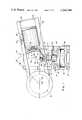
- FIG. 1is a partially cross-sectioned plan view of a preferred embodiment of the invention.
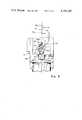
- FIG. 2is a fragmentary plan view of a portion of the lens generating apparatus of FIG. 1 wherein method of adjusting a tool cutting radius is illustrated.
- generator 10is comprised of machine base 12 which supports cutter head 14 and pivot post 16.
- Work supporting head 18which may be adjusted toward and away from cutter head 14 is carried by ways 20 and adaptor 22, e.g. a tapered shank, receives a conventionally or otherwise blocked lens L to be surface generated according to the invention.
- Cutter head 14includes motor driven spindle 24 which supports tool carrier 26.
- Carrier 26in turn, is provided with tool post 28 and tool 30 is extended diametrically through post 28 toward lens L.
- Clamp screw 32is used to fix tool 30 with its effective cutting edge, i.e. tip 34, at a desired distance from post 28. With such a setting of tool 30 in post 28 and rotational adjustment of post 28 about its axis, there may be established a given radius of curvature R 1 (FIG. 2) about which tip 34 will rotate with rotation of carrier 26.
- Clamp screw 36is tightened when all adjustments for establishing the aforesaid radial distance R 1 are completed.
- the structure of tool carrier 26provides for universal adjustment of radial distance R 1 .
- R 1becomes shorter as shown by arrow R 1a .
- R 1becomes longer as shown by arrow R 1b .
- the other radius of curvature R 2(FIG. 1) to be produced orthogonally (e.g. in the spherical meridian) is established by adjusting tool carrier 26 toward or away from axis 38 of pivot post 16 by movement of slide 40 along ways 42 on base slide 44.
- Radius R 2corresponds to the distance from tip 34 of tool 30 to axis 38 of pivot post 16 and its setting is preferably established after the aforesaid angular setting of tool 30 in carrier 26.
- the effective cutting edge of tip 34is preferably positioned on a line 46 which is perpendicular to the axis of rotation 48 of tool carrier 26 and intersects axis 38 of pivot post 16. This is accomplished with movement of base slide 44 as needed along ways 45 of machine base 12.
- Surface S of lens Lis generated to a true toric shape of cylinder radius R 1 and spherical radius R 2 by bringing lens L into working contact with tool 30.
- Thismay be accomplished by initially moving work supporting head 18 toward tool 30 along ways 20 to the point of bringing the uncut lens surface S beyond tip 34 a distance equal to the depth of cut desired.
- This setting of the work supporting headmay be effected prior to rotating tool carrier 26 or by feeding surface S of lens L into tool 30 while rotating the tool carrier as indicated by arrow 50 (FIG. 1).
- vernier scales 52 and 54may also be incorporated in the sliding mechanisms of head 18 and tool carrier 26 to facilitate proper setting thereof before locking.
- a similar vernier scale 56may be provided for aiding in the setting of base slide 44 for tool carrier 26 on machine base 12.
- manual rotational adjustment and setting of tool post 28can be facilitated by circular vernier scale 58.
- motor driven mechanisms operating under data input from computer or microprocessor meansmay be incorporated in the apparatus of FIGS. 1 and 2 for automatically performing the adjustments of tool and work supporting heads and/or rotation of tool post 30.
- An alternative to the movement of work supporting head toward tool 30 for establishing the aforesaid lens/tool setting and working relationshipmay be an arrangement for moving the entire system of tool carrier 26 and pivot post 16 as a unit along a machine base toward and away from supporting head 18 which would be fixed upon the machine base.
- the generating of surface S to a true toric shape with continuous rotation of tool 30 about axis 48is accomplished by swinging lens L clockwise as viewed in FIG. 1 about axis 38 of pivot post 16 to the position shown with broken line illustrated and labelled L 1 .
- Thisis effected by manually swinging or motor driving head 18 and ways 20 as a unit pivotally about post 16.
- generator 10may be designed so that tool carrier 26 and its associated mechanisms are themselves pivotable as a unit about axis 38 while work supporting head 18 is held stationary on the machine base during a lens surface generating operation.
- Generator 10is adaptable to the surfacing of glass or plastic workpieces with proper selection of cutting tip 34.
- the surfacing of a lens L formed of glasscan best be accomplished with a diamond cutting tip while carbides and tool steel will suffice for the cutting of plastic lenses such as those formed of a polycarbonate or cast allyl diglycol carbonate.
- tool cutting edge inserts formed of natural or synthetic diamonds or sintered diamondsare suggested. Natural single crystal or polycrystalline diamonds are preferred.
- generator 10has thus far referred to the cutting of toric curvatures on workpieces of glass or plastic, it should be appreciated that by rendering radial distances R 1 and R 2 equal, the resulting generated surface S would be spherical in shape.
- a spherical surfacemay be produced upon the lens.
Landscapes
- Engineering & Computer Science (AREA)
- Mechanical Engineering (AREA)
- Grinding And Polishing Of Tertiary Curved Surfaces And Surfaces With Complex Shapes (AREA)
- Turning (AREA)
Abstract
Description
Claims (7)
Priority Applications (9)
| Application Number | Priority Date | Filing Date | Title |
|---|---|---|---|
| US06/069,402US4264249A (en) | 1979-08-24 | 1979-08-24 | Toric surface generator |
| CA000355144ACA1139103A (en) | 1979-08-24 | 1980-06-30 | Toric surface generator |
| JP9944180AJPS5633263A (en) | 1979-08-24 | 1980-07-22 | Torus grinding device |
| GB8024658AGB2056895B (en) | 1979-08-24 | 1980-07-28 | Toric surface generator |
| MX183566AMX152998A (en) | 1979-08-24 | 1980-08-15 | IMPROVED APPARATUS TO FORM TORIC SURFACES OF LENSES |
| FR8018146AFR2463751A1 (en) | 1979-08-24 | 1980-08-19 | OSCURAL SURFACE GENERATOR, IN PARTICULAR FOR OPHTHALMIC LENSES |
| CH636080ACH638711A5 (en) | 1979-08-24 | 1980-08-22 | SURFACING APPARATUS FOR LENS. |
| BR8005343ABR8005343A (en) | 1979-08-24 | 1980-08-22 | LENS SURFACE FINISHING APPLIANCE |
| DE19803031942DE3031942A1 (en) | 1979-08-24 | 1980-08-25 | DEVICE FOR PROCESSING LENS SURFACES. |
Applications Claiming Priority (1)
| Application Number | Priority Date | Filing Date | Title |
|---|---|---|---|
| US06/069,402US4264249A (en) | 1979-08-24 | 1979-08-24 | Toric surface generator |
Publications (1)
| Publication Number | Publication Date |
|---|---|
| US4264249Atrue US4264249A (en) | 1981-04-28 |
Family
ID=22088753
Family Applications (1)
| Application Number | Title | Priority Date | Filing Date |
|---|---|---|---|
| US06/069,402Expired - LifetimeUS4264249A (en) | 1979-08-24 | 1979-08-24 | Toric surface generator |
Country Status (9)
| Country | Link |
|---|---|
| US (1) | US4264249A (en) |
| JP (1) | JPS5633263A (en) |
| BR (1) | BR8005343A (en) |
| CA (1) | CA1139103A (en) |
| CH (1) | CH638711A5 (en) |
| DE (1) | DE3031942A1 (en) |
| FR (1) | FR2463751A1 (en) |
| GB (1) | GB2056895B (en) |
| MX (1) | MX152998A (en) |
Cited By (14)
| Publication number | Priority date | Publication date | Assignee | Title |
|---|---|---|---|---|
| US4333368A (en)* | 1980-07-15 | 1982-06-08 | Kollmorgen Technologies Corporation | Method and apparatus for generating aspherical surfaces of revolution |
| US4455901A (en)* | 1981-10-09 | 1984-06-26 | Bausch & Lomb Incorporated | Apparatus for controlling lathed contact lens thickness |
| US4574527A (en)* | 1984-10-05 | 1986-03-11 | Craxton Robert S | Toric lens generating |
| US4592684A (en)* | 1982-03-22 | 1986-06-03 | Sira Limited | Method and apparatus for producing aspherical surfaces |
| US4680998A (en)* | 1984-08-28 | 1987-07-21 | Bausch & Lomb Incorporated | Toric lenses, method and apparatus for making same |
| US4884482A (en)* | 1988-11-22 | 1989-12-05 | Citycrown, Inc. | Method and apparatus for cutting an aspheric surface on a workpiece |
| US4947715A (en)* | 1988-11-22 | 1990-08-14 | Citycrown, Inc. | Method and apparatus for cutting an aspheric surface on a workpiece |
| US5217335A (en)* | 1990-04-24 | 1993-06-08 | National Optronics, Inc. | Plastic lens generator and method |
| US5231587A (en)* | 1990-07-12 | 1993-07-27 | Loh Optical Machinery, Inc. | Computer controlled lens surfacer |
| US5344261A (en)* | 1993-06-01 | 1994-09-06 | Cliber Richard M | Lens generator and tool cutter |
| US5411430A (en)* | 1991-09-25 | 1995-05-02 | Hitachi Ltd. | Scanning optical device and method for making a hybrid scanning lens used therefor |
| US20060264843A1 (en)* | 2000-07-11 | 2006-11-23 | Fangrow Thomas F Jr | Medical valve with positive flow characteristics |
| US20070049175A1 (en)* | 2005-08-29 | 2007-03-01 | Edge Technologies, Inc. | Diamond tool blade with circular cutting edge |
| CN113732891A (en)* | 2021-08-09 | 2021-12-03 | 王迪雅 | Arc convex surface processing control adjustment mechanism |
Families Citing this family (1)
| Publication number | Priority date | Publication date | Assignee | Title |
|---|---|---|---|---|
| DE4243658C2 (en)* | 1992-12-23 | 1995-01-26 | Jenalens Kontaktlinsen Tech | Method and arrangement for machining a toric aspherical concave surface on a contact lens blank |
Citations (9)
| Publication number | Priority date | Publication date | Assignee | Title |
|---|---|---|---|---|
| US1580006A (en)* | 1922-12-29 | 1926-04-06 | Barney Oldfield Mfg Company | Machine for cutting compound curves |
| US1711801A (en)* | 1926-10-13 | 1929-05-07 | Bausch & Lomb | Machine for producing lens-grinding tools |
| US2548418A (en)* | 1947-12-19 | 1951-04-10 | American Optical Corp | Surfacing machine |
| US2633675A (en)* | 1950-06-10 | 1953-04-07 | American Optical Corp | Surfacing machine |
| US2724218A (en)* | 1953-08-19 | 1955-11-22 | American Optical Corp | Surfacing machines |
| US3117396A (en)* | 1961-01-17 | 1964-01-14 | American Optical Corp | Lens grinding apparatus and method |
| US3492764A (en)* | 1967-03-28 | 1970-02-03 | American Optical Corp | Lens generating method |
| US3624969A (en)* | 1970-07-15 | 1971-12-07 | American Optical Corp | Lens generating apparatus |
| US3670460A (en)* | 1970-06-01 | 1972-06-20 | Senoptics Inc | Tool positioning means for lens grinder |
Family Cites Families (4)
| Publication number | Priority date | Publication date | Assignee | Title |
|---|---|---|---|---|
| DE1252555B (en)* | 1968-11-28 | Coburn Manufacturing Company, Inc., Muskogee, OkIa. (V. St. A.) | Device for maintaining the same thickness for lenses on a radius milling machine | |
| GB908706A (en)* | 1958-07-21 | 1962-10-24 | Ass Elect Ind | Improvements relating to the manufacture of hollow metal enclosure walls |
| DE2258152A1 (en)* | 1972-11-28 | 1974-06-20 | Wilhelm H Spira | METHOD AND DEVICE FOR GENERATING TORICAL AREAS |
| US3902277A (en)* | 1974-04-01 | 1975-09-02 | Itek Corp | Method and apparatus for generating toric surfaces by the use of a peripheral surfacing tool |
- 1979
- 1979-08-24USUS06/069,402patent/US4264249A/ennot_activeExpired - Lifetime
- 1980
- 1980-06-30CACA000355144Apatent/CA1139103A/ennot_activeExpired
- 1980-07-22JPJP9944180Apatent/JPS5633263A/enactiveGranted
- 1980-07-28GBGB8024658Apatent/GB2056895B/ennot_activeExpired
- 1980-08-15MXMX183566Apatent/MX152998A/enunknown
- 1980-08-19FRFR8018146Apatent/FR2463751A1/enactiveGranted
- 1980-08-22CHCH636080Apatent/CH638711A5/ennot_activeIP Right Cessation
- 1980-08-22BRBR8005343Apatent/BR8005343A/enunknown
- 1980-08-25DEDE19803031942patent/DE3031942A1/ennot_activeCeased
Patent Citations (9)
| Publication number | Priority date | Publication date | Assignee | Title |
|---|---|---|---|---|
| US1580006A (en)* | 1922-12-29 | 1926-04-06 | Barney Oldfield Mfg Company | Machine for cutting compound curves |
| US1711801A (en)* | 1926-10-13 | 1929-05-07 | Bausch & Lomb | Machine for producing lens-grinding tools |
| US2548418A (en)* | 1947-12-19 | 1951-04-10 | American Optical Corp | Surfacing machine |
| US2633675A (en)* | 1950-06-10 | 1953-04-07 | American Optical Corp | Surfacing machine |
| US2724218A (en)* | 1953-08-19 | 1955-11-22 | American Optical Corp | Surfacing machines |
| US3117396A (en)* | 1961-01-17 | 1964-01-14 | American Optical Corp | Lens grinding apparatus and method |
| US3492764A (en)* | 1967-03-28 | 1970-02-03 | American Optical Corp | Lens generating method |
| US3670460A (en)* | 1970-06-01 | 1972-06-20 | Senoptics Inc | Tool positioning means for lens grinder |
| US3624969A (en)* | 1970-07-15 | 1971-12-07 | American Optical Corp | Lens generating apparatus |
Cited By (18)
| Publication number | Priority date | Publication date | Assignee | Title |
|---|---|---|---|---|
| US4333368A (en)* | 1980-07-15 | 1982-06-08 | Kollmorgen Technologies Corporation | Method and apparatus for generating aspherical surfaces of revolution |
| US4455901A (en)* | 1981-10-09 | 1984-06-26 | Bausch & Lomb Incorporated | Apparatus for controlling lathed contact lens thickness |
| US4592684A (en)* | 1982-03-22 | 1986-06-03 | Sira Limited | Method and apparatus for producing aspherical surfaces |
| US4680998A (en)* | 1984-08-28 | 1987-07-21 | Bausch & Lomb Incorporated | Toric lenses, method and apparatus for making same |
| US4574527A (en)* | 1984-10-05 | 1986-03-11 | Craxton Robert S | Toric lens generating |
| US4884482A (en)* | 1988-11-22 | 1989-12-05 | Citycrown, Inc. | Method and apparatus for cutting an aspheric surface on a workpiece |
| US4947715A (en)* | 1988-11-22 | 1990-08-14 | Citycrown, Inc. | Method and apparatus for cutting an aspheric surface on a workpiece |
| US5217335A (en)* | 1990-04-24 | 1993-06-08 | National Optronics, Inc. | Plastic lens generator and method |
| US5231587A (en)* | 1990-07-12 | 1993-07-27 | Loh Optical Machinery, Inc. | Computer controlled lens surfacer |
| US5411430A (en)* | 1991-09-25 | 1995-05-02 | Hitachi Ltd. | Scanning optical device and method for making a hybrid scanning lens used therefor |
| US5344261A (en)* | 1993-06-01 | 1994-09-06 | Cliber Richard M | Lens generator and tool cutter |
| US20060264843A1 (en)* | 2000-07-11 | 2006-11-23 | Fangrow Thomas F Jr | Medical valve with positive flow characteristics |
| US20070049175A1 (en)* | 2005-08-29 | 2007-03-01 | Edge Technologies, Inc. | Diamond tool blade with circular cutting edge |
| US20080026678A1 (en)* | 2005-08-29 | 2008-01-31 | Kim George A | Diamond tool blade with circular cutting edge |
| US7390242B2 (en)* | 2005-08-29 | 2008-06-24 | Edge Technologies, Inc. | Diamond tool blade with circular cutting edge |
| US7524237B2 (en) | 2005-08-29 | 2009-04-28 | Kim George A | Diamond tool blade with circular cutting edge |
| CN113732891A (en)* | 2021-08-09 | 2021-12-03 | 王迪雅 | Arc convex surface processing control adjustment mechanism |
| CN113732891B (en)* | 2021-08-09 | 2022-08-16 | 成都润驰精密电子有限公司 | Arc convex surface processing control adjustment mechanism |
Also Published As
| Publication number | Publication date |
|---|---|
| BR8005343A (en) | 1981-03-04 |
| GB2056895B (en) | 1983-02-02 |
| CH638711A5 (en) | 1983-10-14 |
| FR2463751A1 (en) | 1981-02-27 |
| JPS5633263A (en) | 1981-04-03 |
| JPS63185B2 (en) | 1988-01-06 |
| DE3031942A1 (en) | 1981-03-12 |
| MX152998A (en) | 1986-07-16 |
| FR2463751B1 (en) | 1984-03-02 |
| GB2056895A (en) | 1981-03-25 |
| CA1139103A (en) | 1983-01-11 |
Similar Documents
| Publication | Publication Date | Title |
|---|---|---|
| US4264249A (en) | Toric surface generator | |
| US2633675A (en) | Surfacing machine | |
| US7281967B2 (en) | Machine for grinding optical lenses | |
| US3117396A (en) | Lens grinding apparatus and method | |
| US2382257A (en) | Manufacture of piezoelectric oscillator blanks | |
| US2413436A (en) | Grinding machine | |
| US2286361A (en) | Abrading machine | |
| GB1200822A (en) | Improvements in or relating to the manufacture of lenses | |
| GB1032049A (en) | Lens generating method and apparatus | |
| US3835528A (en) | Sphere and angle turning attachment for milling machines | |
| US3977279A (en) | Lathe for generating spherical or aspherical surfaces on workpieces | |
| US3624969A (en) | Lens generating apparatus | |
| US3289355A (en) | Automatic lens grinding machine | |
| JPH08318456A (en) | Spindle tapered hole re-boring device | |
| GB2058619A (en) | Lens surface generating apparatus | |
| US3704554A (en) | Lens processing machine with movable workpiece spindle | |
| US3626436A (en) | Machine for sharpening twist drills | |
| US4114486A (en) | Lathe for generating spherical or aspherical surfaces on workpieces, method for generating aspherical surfaces on workpieces and workpiece having aspherical surface | |
| US4271636A (en) | Lens generating apparatus | |
| US2849840A (en) | Method and apparatus for grinding nail cutter dies | |
| US2179388A (en) | Engraving machine or the like | |
| US5085007A (en) | Toric lens fining apparatus | |
| US4817338A (en) | Grinding head for a machine for grinding helically grooved cutting tools | |
| JPH04135149A (en) | Cylinder grinder | |
| JPH01316127A (en) | Working method for screw |
Legal Events
| Date | Code | Title | Description |
|---|---|---|---|
| STCF | Information on status: patent grant | Free format text:PATENTED CASE | |
| AS | Assignment | Owner name:AO,INC.SOUTHBRIDGE, MASS. A CORP OF DE. Free format text:ASSIGNMENT OF ASSIGNORS INTEREST.;ASSIGNOR:AMERICAN OPTICAL CORPORATION;REEL/FRAME:004056/0229 Effective date:19820513 Owner name:WARNER-LAMBERT TECHNOLOGIES, INC., A TX CORP. Free format text:CONDITIONAL ASSIGNMENT;ASSIGNOR:AO, INC. A DE CORP.;REEL/FRAME:004041/0934 Effective date:19820528 | |
| AS | Assignment | Owner name:WARNER-LAMBERT CANADA, INC. Free format text:SECURITY INTEREST;ASSIGNOR:AO, INC., A DE CORP.;REEL/FRAME:004073/0046 Effective date:19820528 Owner name:WARNER-LAMBERT TECHNOLOGIES, INC., A DE CORP. Free format text:SECURITY INTEREST;ASSIGNOR:AO, INC., A DE CORP.;REEL/FRAME:004073/0046 Effective date:19820528 | |
| AS | Assignment | Owner name:IRVING TRUST COMPANY, ONE WALL ST, NEW YORK, N.Y. Free format text:ASSIGNMENT OF ASSIGNORS INTEREST.;ASSIGNOR:AO, INC. A CORP. OF DEL.;REEL/FRAME:004073/0675 Effective date:19820621 Owner name:IRVING TRUST COMPANY, NEW YORK Free format text:ASSIGNMENT OF ASSIGNORS INTEREST;ASSIGNOR:AO, INC.;REEL/FRAME:004073/0675 Effective date:19820621 | |
| AS | Assignment | Owner name:AMERICAN OPTICAL CORPORATION, A CORP. OF DE. Free format text:ASSIGNMENT OF ASSIGNORS INTEREST.;ASSIGNORS:AO, INC., A DE. CORP.;WARNER-LAMBERT TECHNOLOGIES, INC., A TX CORP.;IRVING TRUST COMPANY, A NY CORP.;REEL/FRAME:004477/0409;SIGNING DATES FROM 19850923 TO 19851023 | |
| AS | Assignment | Owner name:IRVING TRUST COMPANY Free format text:SECURITY INTEREST;ASSIGNORS:AMERICAN OPTICAL CORPORATION;RADIAC ABRASIVES (EAST) INC.,;RADIAC ABRASIVES (WEST) INC.,;REEL/FRAME:004918/0235 Effective date:19880527 Owner name:IRVING TRUST COMPANY, NEW YORK Free format text:SECURITY INTEREST;ASSIGNORS:AMERICAN OPTICAL CORPORATION;RADIAC ABRASIVES (EAST) INC.;RADIAC ABRASIVES (WEST) INC.;REEL/FRAME:004918/0235 Effective date:19880527 | |
| AS | Assignment | Owner name:AMERICAN OPTICAL CORPORATION Free format text:RELEASED BY SECURED PARTY;ASSIGNOR:BANK OF NEW YORK, THE (FORMERLY KNOWN AS IRVING TRUST COMPANY);REEL/FRAME:005535/0035 Effective date:19900413 Owner name:RADIAC ABRASIVES (EAST) INC. Free format text:RELEASED BY SECURED PARTY;ASSIGNOR:BANK OF NEW YORK, THE (FORMERLY KNOWN AS IRVING TRUST COMPANY);REEL/FRAME:005535/0035 Effective date:19900413 Owner name:RADIAC ABRASIVES (WEST) INC. Free format text:RELEASED BY SECURED PARTY;ASSIGNOR:BANK OF NEW YORK, THE (FORMERLY KNOWN AS IRVING TRUST COMPANY);REEL/FRAME:005535/0035 Effective date:19900413 | |
| AS | Assignment | Owner name:SOLA INTERNATIONAL INC., CALIFORNIA Free format text:ASSIGNMENT OF ASSIGNORS INTEREST;ASSIGNORS:AO, INC.;AMERICAN OPTICAL CORPORATION;REEL/FRAME:008048/0061 Effective date:19960506 |