US4263922A - Method and device for collecting, transporting, and delivering micro samples of blood - Google Patents
Method and device for collecting, transporting, and delivering micro samples of bloodDownload PDFInfo
- Publication number
- US4263922A US4263922AUS06/071,702US7170279AUS4263922AUS 4263922 AUS4263922 AUS 4263922AUS 7170279 AUS7170279 AUS 7170279AUS 4263922 AUS4263922 AUS 4263922A
- Authority
- US
- United States
- Prior art keywords
- adapter
- blood
- analyzer
- capillary tube
- tip
- Prior art date
- Legal status (The legal status is an assumption and is not a legal conclusion. Google has not performed a legal analysis and makes no representation as to the accuracy of the status listed.)
- Expired - Lifetime
Links
Images
Classifications
- B—PERFORMING OPERATIONS; TRANSPORTING
- B01—PHYSICAL OR CHEMICAL PROCESSES OR APPARATUS IN GENERAL
- B01L—CHEMICAL OR PHYSICAL LABORATORY APPARATUS FOR GENERAL USE
- B01L3/00—Containers or dishes for laboratory use, e.g. laboratory glassware; Droppers
- B01L3/56—Labware specially adapted for transferring fluids
- B01L3/565—Seals
- A—HUMAN NECESSITIES
- A61—MEDICAL OR VETERINARY SCIENCE; HYGIENE
- A61B—DIAGNOSIS; SURGERY; IDENTIFICATION
- A61B5/00—Measuring for diagnostic purposes; Identification of persons
- A61B5/15—Devices for taking samples of blood
- A61B5/150007—Details
- A61B5/150015—Source of blood
- A61B5/15003—Source of blood for venous or arterial blood
- A—HUMAN NECESSITIES
- A61—MEDICAL OR VETERINARY SCIENCE; HYGIENE
- A61B—DIAGNOSIS; SURGERY; IDENTIFICATION
- A61B5/00—Measuring for diagnostic purposes; Identification of persons
- A61B5/15—Devices for taking samples of blood
- A61B5/150007—Details
- A61B5/150343—Collection vessels for collecting blood samples from the skin surface, e.g. test tubes, cuvettes
- A—HUMAN NECESSITIES
- A61—MEDICAL OR VETERINARY SCIENCE; HYGIENE
- A61B—DIAGNOSIS; SURGERY; IDENTIFICATION
- A61B5/00—Measuring for diagnostic purposes; Identification of persons
- A61B5/15—Devices for taking samples of blood
- A61B5/150007—Details
- A61B5/150374—Details of piercing elements or protective means for preventing accidental injuries by such piercing elements
- A61B5/150381—Design of piercing elements
- A61B5/150389—Hollow piercing elements, e.g. canulas, needles, for piercing the skin
- A—HUMAN NECESSITIES
- A61—MEDICAL OR VETERINARY SCIENCE; HYGIENE
- A61B—DIAGNOSIS; SURGERY; IDENTIFICATION
- A61B5/00—Measuring for diagnostic purposes; Identification of persons
- A61B5/15—Devices for taking samples of blood
- A61B5/150007—Details
- A61B5/150374—Details of piercing elements or protective means for preventing accidental injuries by such piercing elements
- A61B5/150381—Design of piercing elements
- A61B5/150503—Single-ended needles
- A—HUMAN NECESSITIES
- A61—MEDICAL OR VETERINARY SCIENCE; HYGIENE
- A61B—DIAGNOSIS; SURGERY; IDENTIFICATION
- A61B5/00—Measuring for diagnostic purposes; Identification of persons
- A61B5/15—Devices for taking samples of blood
- A61B5/150007—Details
- A61B5/150374—Details of piercing elements or protective means for preventing accidental injuries by such piercing elements
- A61B5/150534—Design of protective means for piercing elements for preventing accidental needle sticks, e.g. shields, caps, protectors, axially extensible sleeves, pivotable protective sleeves
- A61B5/15058—Joining techniques used for protective means
- A61B5/150587—Joining techniques used for protective means by friction fit
- A—HUMAN NECESSITIES
- A61—MEDICAL OR VETERINARY SCIENCE; HYGIENE
- A61B—DIAGNOSIS; SURGERY; IDENTIFICATION
- A61B5/00—Measuring for diagnostic purposes; Identification of persons
- A61B5/15—Devices for taking samples of blood
- A61B5/150007—Details
- A61B5/150374—Details of piercing elements or protective means for preventing accidental injuries by such piercing elements
- A61B5/150534—Design of protective means for piercing elements for preventing accidental needle sticks, e.g. shields, caps, protectors, axially extensible sleeves, pivotable protective sleeves
- A61B5/150694—Procedure for removing protection means at the time of piercing
- A61B5/150717—Procedure for removing protection means at the time of piercing manually removed
- A—HUMAN NECESSITIES
- A61—MEDICAL OR VETERINARY SCIENCE; HYGIENE
- A61B—DIAGNOSIS; SURGERY; IDENTIFICATION
- A61B5/00—Measuring for diagnostic purposes; Identification of persons
- A61B5/15—Devices for taking samples of blood
- A61B5/150007—Details
- A61B5/150732—Needle holders, for instance for holding the needle by the hub, used for example with double-ended needle and pre-evacuated tube
- A—HUMAN NECESSITIES
- A61—MEDICAL OR VETERINARY SCIENCE; HYGIENE
- A61B—DIAGNOSIS; SURGERY; IDENTIFICATION
- A61B5/00—Measuring for diagnostic purposes; Identification of persons
- A61B5/15—Devices for taking samples of blood
- A61B5/150007—Details
- A61B5/150755—Blood sample preparation for further analysis, e.g. by separating blood components or by mixing
- A—HUMAN NECESSITIES
- A61—MEDICAL OR VETERINARY SCIENCE; HYGIENE
- A61B—DIAGNOSIS; SURGERY; IDENTIFICATION
- A61B5/00—Measuring for diagnostic purposes; Identification of persons
- A61B5/15—Devices for taking samples of blood
- A61B5/150007—Details
- A61B5/150763—Details with identification means
- A61B5/150786—Optical identification systems, e.g. bar codes, colour codes
- A—HUMAN NECESSITIES
- A61—MEDICAL OR VETERINARY SCIENCE; HYGIENE
- A61B—DIAGNOSIS; SURGERY; IDENTIFICATION
- A61B5/00—Measuring for diagnostic purposes; Identification of persons
- A61B5/15—Devices for taking samples of blood
- A61B5/153—Devices specially adapted for taking samples of venous or arterial blood, e.g. with syringes
- A—HUMAN NECESSITIES
- A61—MEDICAL OR VETERINARY SCIENCE; HYGIENE
- A61B—DIAGNOSIS; SURGERY; IDENTIFICATION
- A61B5/00—Measuring for diagnostic purposes; Identification of persons
- A61B5/15—Devices for taking samples of blood
- A61B5/150007—Details
- A61B5/150206—Construction or design features not otherwise provided for; manufacturing or production; packages; sterilisation of piercing element, piercing device or sampling device
- A61B5/150259—Improved gripping, e.g. with high friction pattern or projections on the housing surface or an ergonometric shape
Definitions
- syringesArterial blood for diagnostic testing in blood gas analyzers is commonly collected by means of syringes, vacuum tubes, or capillary tubes, each of which presents substantial disadvantages and difficulties.
- Syringesmust be airtight and, if formed of glass, usually require lubrication.
- the entire dead space between the needle and the plungermust be filled with a heparin solution, a procedure requiring considerable care to avoid small air bubbles that may cling to the barrel or to the plunger and prevent anerobic sampling. After collecting the blood, any residual air in the syringe must be expelled to prevent the loss of carbon dioxide from the blood by diffusion.
- heparinized capillary tubeshas the advantage over the other techniques of avoiding the collection of excessively large samples, a particularly important consideration in pediatric studies, but in other respects the procedures used with such capillary tubes involve the same problems of collecting, transporting, and delivering samples under substantially anerobic conditions.
- a main object of this inventiontherefore lies in providing a method which greatly simplifies the procedures for sampling arterial (and venous) blood, and for doing so in a way that minimizes risks of exposure to air and increases the reproducibility and accuracy of test results.
- Another objectis to provide a relatively safe, uncomplicated, inexpensive, and highly effective method for drawing micro samples of arterial or venous blood and for storing, transporting, and delivering such samples to suitable blood analysis equipment.
- the deviceincludes a capillary tube, an adapter-handle detachably connected to the tube, and a hypodermic needle detachably mounted on the adapter-handle.
- a protective covermay extend over the needle, and at least one end cap is provided to seal the end (or ends) of the capillary tube after a blood sample is collected.
- the adapter-handleis formed of resilient plastic material and has integral body and tip sections.
- a boreextends longitudinally through both sections with that portion of the bore within the body section tapering gradually inwardly at an angle of approximately 2 to 6 degrees measured from the axis of the adapter-handle.
- the tip of the adapter-handlehas reduced outside cross sectional dimensions and is tapered both internally and externally.
- the external taperis that of a conventional Luer taper, permitting the tip to be inserted and retained within the hub of a standard hypodermic needle having a female Luer taper.
- the internal taper of the tipextends inwardly at an angle in the range of about 1 to 3 degrees and is dimensioned to receive and sealingly engage the inlet tubes of various models of commercially-available blood gas analyzers.
- a more sharply tapered surface of a frusto-conical intermediate sectionis adapted to engage and seal against the mouths of the inlet passages of other types of available blood gas analyzers.
- the heparin-coated capillary tube, the resilient adapter-handle, and the needleare assembled.
- a suitable artery or veinis punctured and the capillary tube is filled by reason of arterial or venous pressure.
- the free end of the capillary tubeis then capped, thereby preventing blood from escaping from either end of the capillary tube when the needle is withdrawn from the puncture site.
- the usersimply mixes the sample with the heparin within the tube, detaches and discards the needle, couples the tip portion of the adapter-handle to a blood analyzer, removes the cap, and allows the micro sample to be drawn into the analyzer.
- the userdetaches (and discards) the adapter-handle, replaces it with an end cap, and then, following mixing, transit and/or storage, removes both caps, replacing one with a fresh adapter-handle for delivering the sample to the inlet of a blood analyzer in the manner already described.
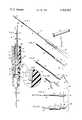
- FIG. 1is a side view of a device embodying this invention, the device being shown with its needle cover removed (but with phantom lines showing its attached position) for clarity of illustration.
- FIG. 2is an enlarged longitudinal side view, taken partly in section, of the device.
- FIG. 3is a still further enlarged fragmentary view of an indicated portion of FIG. 2 illustrating the functional relationship between the parts.
- FIG. 4illustrates a first step in the method during which blood is drawn into the microcapillary tube.
- FIG. 5illustrates a further step in which the needle is removed and the distal end of the capillary tube is capped.
- FIG. 5Adepicts a further step which may be used when access to a blood analyzer is delayed.
- FIG. 6represents a further step of delivering the blood to an analyzer having a female connector forming the inlet thereof.
- FIG. 6Adepicts the delivery step when the analyzer is provided with a male connector at the inlet thereof.
- the numeral 10generally designates a device comprising an adapter-handle 11, a needle assembly 12, and a microcapillary tube 13.
- Such componentsmay be supplied to the user in assembled form as shown, or they may be supplied as separate parts to be assembled by the user. In either case, a suitable cover 14 should be attached to the needle 12 to maintain sterility of the needle until use.
- An end cap 15may be fitted upon the distal end of the capillary tube, and the entire assembly may be supplied in sterile condition within a suitable wrapper (not shown).
- the needle assembly 12 shown most clearly in FIG. 2is conventional in construction and includes a hollow needle 16 secured to a cup-shaped hub 17.
- hub 17is formed of rigid plastic such as, for example, polystyrene, although it is to be understood that other materials such as metals might be used.
- the open end of the hubprovides the entrance to a tapered cavity 18 dimensioned to receive and frictionally engage the tip of adapter 11.
- the inward taper of the cavity 18is commonly referred to as a standard Luer taper, meaning that the hub will mate tightly with a tapered syringe tip identified by the name of its originator.
- Such taperis described in Federal Specification GG-N-196 and corresponds to an angle approximately 1°43'6" measured from the axis of the needle assembly 12 (or an included angle of about 3°26'12").
- the metal needle 16should be of relatively small gauge (No. 25 or less) and the opening at the mouth of the cavity should be approximately 0.165 of an inch in diameter.
- the tubular needle cover 14is entirely conventional and serves simply to protect the pointed hollow needle 16 as well as objects which the needle might otherwise contact, and to help maintain sterility of the needle.
- the covermay be formed of any of a variety of rigid or semi-rigid polymers such as, for example, polypropylene or other polyolefins.
- the microcapillary tubeis also conventional, being formed of glass and usually being of a standard length of 100 millimeters.
- Such a tubehas a through-bore which is precisely dimensioned to contain a sample of predetermined volume, ordinarily either 100 or 200 microliters ( ⁇ l).
- Color coded bands 19 and 20indicate to the user both the capacity of the tube and the fact that its interior surfaces have been heparinized to prevent coagulation of a blood sample drawn into the tube.
- End cap 15is preferably formed of ethyl vinyl acetate, silicone rubber, or some other suitable resilient plastic material and defines a tapered cavity for snugly and sealingly receiving the end of glass capillary tube 13. While only a single end cap is needed in certain uses of the blood collection device, a second identical end cap may be supplied to the user where temporary sealing of the opposite end of the capillary tube is also deemed necessary or desirable.
- the adapter-handle 11is also formed from a relatively soft resilient elastomer such as ethyl vinyl acetate or silicone rubber and is composed of integral body and tip sections 11a and 11b, respectively.
- a bore 21extends through the adapter with that portion 21a of the bore within body section 11a tapering gradually inwardly for receiving and frictionally retaining one end of microcapillary tube 13.
- the gradual taper of bore portion 21a and the resiliency of the material from which the adapter is formednot only insure that a tight frictional seal will be formed between the end of the capillary tube and the adapter but also permits the adapter to form such engagement with standard capillary tubes of different diameters and capacities. It will be noted from the enlarged view of FIG.
- bore portion 21bhas a Luer taper similar to that of hub cavity 18 and, consequently, is adapted to mate with the Luer tip of a standard syringe.
- bore portion 21bshould have a maximum diameter at its mouth of approximately 0.165 of an inch.
- the tip section 11b of the adapteris reduced in outside dimensions and has a standard male Luer taper allowing the distal portion of the tip to be received tightly within the cavity 18 of the needle hub.
- the angle of taper of the tip's outer surfaceshould match closely the angle of inside taper of the hub with the maximum outside diameter of the tip at point 23 exceeding the inside diameter at the mouth of cavity 18.
- a differential of at least 0.003 of an inchshould be provided (0.005 preferred) to insure a snug fluid-tight friction fit between the parts.
- the tipis provided with a flared or frusto-conical outer surface 24.
- the angle of that frusto-conical surface, measured from the axis of the adapter,should fall within the general range of 10° to 30°, an angle of approximately 20° being found particularly effective.
- the frusto-conical surfaceis not merely a transitional surface between the Luer taper of the tip and the cylindrical surface of the body; it provides an inclined stop for limiting the extent of insertion of the adapter into the inlet port of a blood analyzer, and for sealingly engaging that port when delivery of a sample to such an analyzer takes place.
- the internal and external longitudinal surfaces of the tip section 11bare reversely tapered; that is, in addition to having a Luer taper along its outer surface the tip has a reversely-tapered bore portion 21c which gradually and progressively increases in size towards the free end of the tip section.
- the angle of taper y(FIG. 2) should fall generally within the range of 1° to 3° measured from the longitudinal axis of the adapter, the preferred angle of taper being approximately 2°.
- the bore portion 21cshould have a diameter of at least 0.08 of an inch, a preferred dimension being about 0.09 of an inch. As shown, bore portion 21c tapers smoothly and gradually inwardly to merge with bore portion 21a of body section 11a.
- the device 10may be supplied in assembled condition as shown in FIG. 1.
- the devicemay be supplied in disassembled condition, requiring interfitting of the major components by the user.
- the userremoves end cap 15, detaches the protective needle cover 14, and, holding the device by means of the resilient adapter-handle 11, inserts the sterile needle 16 into the blood vessel from which the sample is to be taken.
- blood gas analysisarterial blood is preferred.
- Such bloodmay be obtained by inserting the fine-gauge needle 16 into an artery such as the brachial, radial, femoral, or jugular arteries.
- FIG. 4depicts the sampling step, the outline of the patient's body being generally represented by line 25 and the transparent collection tube shown to be filled with blood taken from the patient. Entry of the needle into an artery is confirmed by the pulsatile filling of the bore of the glass capillary tube, such filling action generally being completed within three seconds and occuring by reason of arterial (or venous) pressure. The user then withdraws the needle and immediately caps the remote end of the capillary tube with cap 15 (FIG. 5). Still holding the device by means of the adapter-handle, the user detaches (and discards) the needle assembly 12. If the blood analyzing equipment is close at hand, the adapter is then simply coupled to the inlet connector of the analyzer to allow the collected blood sample to be drawn into the analyzer where it is tested (FIGS. 6 and 6A).
- the numeral 26generally designates that type of commercially-available blood analyzer having an inlet port 27, the mouth of which is engagable with the tip section of the adapter 11 to provide a temporary seal as the blood sample is aspirated from the capillary tube into the machine.
- the frusto-conical outer surface 24 of the adapteris particularly effective in forming such a seal with the mouth of the instrument and for limiting the extent of insertion of the resilient adapter into the inlet.
- FIG. 6Aschematically depicts a different type of blood analyzer 26' in which the inlet takes the form of a protruding nipple or tube 28 having an outside diameter of approximately 0.08 of an inch.
- the userIn delivering a blood sample to such an analyzer, the user, holding the device by its resilient adapter 11, simply fits the internally tapered tip section 11b on to the inlet tube 28 and allows the blood sample to be drawn into the machine.
- adapter-handle 11may be removed from the filled capillary tube 13 and replaced by a second end cap 15 (FIG. 5A). With both ends of the capillary tube so capped, the collected sample may be mixed, transported, and temporarily stored under refrigeration. Upon arrival at the blood analyzer, one of the end caps is removed and replaced by a fresh adapter 11. The procedure represented in FIG. 6 or 6A is then performed with the distal end cap 15 removed from the capillary tube to permit aspiration of the blood sample into the analyzer.
- the adapter 11is constructed to perform a multiplicity of functions.
- the adapterserves as a resilient handle.
- the usergrips the sampling device by holding the resilient adapter between his fingers.
- the squeezing forcestend to assist in maintaining the capillary tube and adapter in interconnected relation.
- the danger of breakage of the fragile capillary tube, and the risks of possible contamination of the userare reduced.
- the resilient handleprovides limited articulation between the rigid glass tube 13 and the needle assembly 12, thereby reducing the chances of breakage of either rigid part, and, should such breakage happen to occur, the handle serves as a protective sheath between the fractured tube and the user's fingers to prevent injury and possible contamination.
Landscapes
- Health & Medical Sciences (AREA)
- Life Sciences & Earth Sciences (AREA)
- Molecular Biology (AREA)
- Surgery (AREA)
- Biophysics (AREA)
- Pathology (AREA)
- Engineering & Computer Science (AREA)
- Biomedical Technology (AREA)
- Heart & Thoracic Surgery (AREA)
- Medical Informatics (AREA)
- Hematology (AREA)
- Physics & Mathematics (AREA)
- Animal Behavior & Ethology (AREA)
- General Health & Medical Sciences (AREA)
- Public Health (AREA)
- Veterinary Medicine (AREA)
- Clinical Laboratory Science (AREA)
- Chemical & Material Sciences (AREA)
- Chemical Kinetics & Catalysis (AREA)
- Dermatology (AREA)
- Investigating Or Analysing Biological Materials (AREA)
- Measurement Of The Respiration, Hearing Ability, Form, And Blood Characteristics Of Living Organisms (AREA)
Abstract
Description
Claims (11)
Priority Applications (2)
| Application Number | Priority Date | Filing Date | Title |
|---|---|---|---|
| US06/071,702US4263922A (en) | 1979-08-31 | 1979-08-31 | Method and device for collecting, transporting, and delivering micro samples of blood |
| US06/207,372US4393882A (en) | 1979-08-31 | 1980-11-17 | Method and device for collecting, transporting, and delivering micro samples of blood |
Applications Claiming Priority (1)
| Application Number | Priority Date | Filing Date | Title |
|---|---|---|---|
| US06/071,702US4263922A (en) | 1979-08-31 | 1979-08-31 | Method and device for collecting, transporting, and delivering micro samples of blood |
Related Child Applications (1)
| Application Number | Title | Priority Date | Filing Date |
|---|---|---|---|
| US06/207,372DivisionUS4393882A (en) | 1979-08-31 | 1980-11-17 | Method and device for collecting, transporting, and delivering micro samples of blood |
Publications (1)
| Publication Number | Publication Date |
|---|---|
| US4263922Atrue US4263922A (en) | 1981-04-28 |
Family
ID=22103014
Family Applications (2)
| Application Number | Title | Priority Date | Filing Date |
|---|---|---|---|
| US06/071,702Expired - LifetimeUS4263922A (en) | 1979-08-31 | 1979-08-31 | Method and device for collecting, transporting, and delivering micro samples of blood |
| US06/207,372Expired - LifetimeUS4393882A (en) | 1979-08-31 | 1980-11-17 | Method and device for collecting, transporting, and delivering micro samples of blood |
Family Applications After (1)
| Application Number | Title | Priority Date | Filing Date |
|---|---|---|---|
| US06/207,372Expired - LifetimeUS4393882A (en) | 1979-08-31 | 1980-11-17 | Method and device for collecting, transporting, and delivering micro samples of blood |
Country Status (1)
| Country | Link |
|---|---|
| US (2) | US4263922A (en) |
Cited By (27)
| Publication number | Priority date | Publication date | Assignee | Title |
|---|---|---|---|---|
| WO1983003057A1 (en)* | 1982-03-09 | 1983-09-15 | Roald-Franch Walle | Transmission of small volumes of liquid samples |
| US4673386A (en)* | 1986-03-06 | 1987-06-16 | Gordon Mark G | Blood sampler device |
| US4982740A (en)* | 1986-02-26 | 1991-01-08 | Broden Bengt Inge | Method for use in the handling of body fluids |
| US5084034A (en)* | 1990-06-08 | 1992-01-28 | Tufts University | Method for sampling body fluids |
| US5148811A (en)* | 1990-05-15 | 1992-09-22 | Medex, Inc. | Method and apparatus for sampling blood and for monitoring blood pressure |
| US5638828A (en)* | 1993-10-28 | 1997-06-17 | I-Stat Corporation | Fluid sample collection and introduction device and method |
| WO1997029369A1 (en)* | 1996-02-09 | 1997-08-14 | Micro Diagnostic Innovations Nederland B.V. | Method and kit for separating plasma from whole blood |
| US5714125A (en)* | 1996-03-07 | 1998-02-03 | Medical Safety Products, Inc. | Device for collecting a blood sample from a plastic segment tube |
| US5759160A (en)* | 1995-11-20 | 1998-06-02 | Utah Medical Products, Inc. | Blood sampling system |
| US5792166A (en)* | 1996-01-24 | 1998-08-11 | Gordon; Mark G. | Anterior capsulotomy device and procedure |
| US5827305A (en)* | 1996-01-24 | 1998-10-27 | Gordon; Mark G. | Tissue sampling device |
| US6155991A (en)* | 1999-07-01 | 2000-12-05 | Via Christi Research, Inc. | Apparatus and method for collecting blood samples |
| JP2003159235A (en)* | 2001-11-27 | 2003-06-03 | Chemicals Evaluation & Research Institute | Blood collection equipment |
| US20030223915A1 (en)* | 1996-03-07 | 2003-12-04 | Sagstetter William E. | Method for manufacturing a device for collecting a blood sample from a plastic segment tube |
| US20030236497A1 (en)* | 2002-06-25 | 2003-12-25 | Radiometer Medical A/S | Sampler cap |
| US6709428B2 (en) | 2000-05-26 | 2004-03-23 | Baxter International, Inc. | Needle design and manufacturing method for medical applications |
| US20050187532A1 (en)* | 2004-02-24 | 2005-08-25 | Medex, Inc. | Diaphragm-based reservoir for a closed blood sampling system |
| US20100270702A1 (en)* | 2008-01-15 | 2010-10-28 | West Pharmaceutical Services, Inc. | Collet mechanism and method of molding cannula to a syringe barrel |
| US20120131777A1 (en)* | 2010-11-30 | 2012-05-31 | Barry Lyn Holtzman | Golf club shaft extractor |
| WO2013036524A1 (en)* | 2011-09-06 | 2013-03-14 | Pokorney James L | Tapered bore connector |
| USD689188S1 (en) | 2012-07-19 | 2013-09-03 | West Pharmaceutical Services, Inc. | Syringe plunger rod |
| USD693002S1 (en) | 2011-09-21 | 2013-11-05 | West Pharmaceutical Services, Inc. | Hub for medical container |
| US8721603B2 (en) | 2008-01-15 | 2014-05-13 | West Pharmaceutical Services, Inc. | Syringe with co-molded hub and cannula |
| US20180008182A1 (en)* | 2016-07-08 | 2018-01-11 | Tony Randall Wann | Multi-function capillary tube syringe with retractable needle for arterial blood drawing |
| US10827963B2 (en) | 2015-07-29 | 2020-11-10 | Advanced Animal Diagnostics, Inc. | Apparatus for rapid collection of blood from livestock |
| US20210236030A1 (en)* | 2018-07-13 | 2021-08-05 | Hundred Co., Ltd. | Fluid collection injection needle |
| US20220105283A1 (en)* | 2019-02-11 | 2022-04-07 | Intuitive Surgical Operations, Inc. | Medical device insufflation connection |
Families Citing this family (14)
| Publication number | Priority date | Publication date | Assignee | Title |
|---|---|---|---|---|
| SE8400288L (en)* | 1984-01-20 | 1985-07-21 | Anders Edvard Trell | DEVICE FOR TAKING AND SETTING BLOOD SINK |
| US4653511A (en)* | 1984-10-05 | 1987-03-31 | Goch Thomas A | Microsample blood collecting device |
| US4777964A (en)* | 1986-01-02 | 1988-10-18 | David Briggs | System for obtaining blood samples and submitting for testing of aids |
| US5269317A (en)* | 1989-06-08 | 1993-12-14 | Bennett Scientific, Inc. | Intravenous blood sampling apparatus |
| US5257984A (en)* | 1991-10-02 | 1993-11-02 | Norfolk Scientific, Inc. | Blood collector |
| US5353806A (en)* | 1993-03-04 | 1994-10-11 | The Venture Fund Of Washington | Liquid collection device |
| NL1003526C2 (en)* | 1996-07-05 | 1998-01-07 | Sgt Exploitatie Bv | Sealing element intended for closing one end of a capillary gas chromatography column. |
| US7056316B1 (en)* | 1997-01-21 | 2006-06-06 | Vasca, Inc. | Valve port and method for vascular access |
| US20020143297A1 (en)* | 2001-03-30 | 2002-10-03 | Becton, Dickinson And Company | Adaptor for use with point-of-care testing cartridge |
| USD474839S1 (en) | 2002-03-26 | 2003-05-20 | Becton, Dickinson And Company | Adaptor for point of care testing cartridge |
| USD473647S1 (en) | 2002-03-26 | 2003-04-22 | Becton, Dickinson And Company | Adaptor for point of care testing cartridge |
| US7090646B2 (en)* | 2003-09-09 | 2006-08-15 | Westmed, Inc. | Plunger-less syringe for controlling blood flow |
| WO2008157511A1 (en)* | 2007-06-15 | 2008-12-24 | Westmed, Inc. | Plunger-less syringe for controlling blood flow |
| EP3451929A4 (en)* | 2016-05-04 | 2020-07-29 | LHM Innovations Pty Ltd | LIQUID SAMPLING DEVICE AND METHOD FOR USE THEREOF |
Citations (4)
| Publication number | Priority date | Publication date | Assignee | Title |
|---|---|---|---|---|
| US3645252A (en)* | 1968-12-05 | 1972-02-29 | Gilford Instr Labor Inc | Apparatus for sampling blood or the like fluid |
| US3977403A (en)* | 1975-02-24 | 1976-08-31 | The Kendall Company | Catheter adapter |
| US4133304A (en)* | 1977-04-29 | 1979-01-09 | Emde Corporation | Syringe-like apparatus with removable capillary cartridge |
| US4187860A (en)* | 1977-09-01 | 1980-02-12 | The Kendall Company | Arterial blood collection device |
Family Cites Families (4)
| Publication number | Priority date | Publication date | Assignee | Title |
|---|---|---|---|---|
| US3648684A (en)* | 1970-08-04 | 1972-03-14 | Cleora W Barnwell | Device for the direct transfer of blood from a human to culture bottles |
| US3749084A (en)* | 1971-05-03 | 1973-07-31 | A Cucchiara | Sequentially dispensing syringe with multiple needle assembly |
| US4178941A (en)* | 1975-01-20 | 1979-12-18 | Concord Laboratories, Inc. | Method for drawing a blood sample |
| US4266559A (en)* | 1979-04-02 | 1981-05-12 | American Hospital Supply Corporation | Blood sampler |
- 1979
- 1979-08-31USUS06/071,702patent/US4263922A/ennot_activeExpired - Lifetime
- 1980
- 1980-11-17USUS06/207,372patent/US4393882A/ennot_activeExpired - Lifetime
Patent Citations (4)
| Publication number | Priority date | Publication date | Assignee | Title |
|---|---|---|---|---|
| US3645252A (en)* | 1968-12-05 | 1972-02-29 | Gilford Instr Labor Inc | Apparatus for sampling blood or the like fluid |
| US3977403A (en)* | 1975-02-24 | 1976-08-31 | The Kendall Company | Catheter adapter |
| US4133304A (en)* | 1977-04-29 | 1979-01-09 | Emde Corporation | Syringe-like apparatus with removable capillary cartridge |
| US4187860A (en)* | 1977-09-01 | 1980-02-12 | The Kendall Company | Arterial blood collection device |
Cited By (45)
| Publication number | Priority date | Publication date | Assignee | Title |
|---|---|---|---|---|
| WO1983003057A1 (en)* | 1982-03-09 | 1983-09-15 | Roald-Franch Walle | Transmission of small volumes of liquid samples |
| US4982740A (en)* | 1986-02-26 | 1991-01-08 | Broden Bengt Inge | Method for use in the handling of body fluids |
| US4673386A (en)* | 1986-03-06 | 1987-06-16 | Gordon Mark G | Blood sampler device |
| US5148811A (en)* | 1990-05-15 | 1992-09-22 | Medex, Inc. | Method and apparatus for sampling blood and for monitoring blood pressure |
| US5084034A (en)* | 1990-06-08 | 1992-01-28 | Tufts University | Method for sampling body fluids |
| US5779650A (en)* | 1993-10-28 | 1998-07-14 | I-Stat Corporation | Fluid sample collection and introduction device and method |
| US5638828A (en)* | 1993-10-28 | 1997-06-17 | I-Stat Corporation | Fluid sample collection and introduction device and method |
| US5653243A (en)* | 1993-10-28 | 1997-08-05 | I-Stat Corporation | Fluid sample collection and introduction device and method |
| US5666967A (en)* | 1993-10-28 | 1997-09-16 | I-Stat Corporation | Fluid sample collection and introduction device |
| US6010463A (en)* | 1993-10-28 | 2000-01-04 | I-Stat | Fluid sample collection and introduction device and method |
| US6159164A (en)* | 1995-11-20 | 2000-12-12 | Utah Medical Products | Blood sampling system |
| US5759160A (en)* | 1995-11-20 | 1998-06-02 | Utah Medical Products, Inc. | Blood sampling system |
| US5792166A (en)* | 1996-01-24 | 1998-08-11 | Gordon; Mark G. | Anterior capsulotomy device and procedure |
| US5827305A (en)* | 1996-01-24 | 1998-10-27 | Gordon; Mark G. | Tissue sampling device |
| US6245244B1 (en) | 1996-02-09 | 2001-06-12 | Micro Diagnostic Innovations Nederland B.V. | Method and kit for separating plasma from whole blood |
| WO1997029369A1 (en)* | 1996-02-09 | 1997-08-14 | Micro Diagnostic Innovations Nederland B.V. | Method and kit for separating plasma from whole blood |
| US20030223915A1 (en)* | 1996-03-07 | 2003-12-04 | Sagstetter William E. | Method for manufacturing a device for collecting a blood sample from a plastic segment tube |
| US6074612A (en)* | 1996-03-07 | 2000-06-13 | Medical Safety Products, Inc. | Device for collecting a blood sample from a plastic segment tube |
| US6503453B1 (en) | 1996-03-07 | 2003-01-07 | Baxter International, Inc. | Device for collecting a blood sample from a plastic segment tube |
| US5714125A (en)* | 1996-03-07 | 1998-02-03 | Medical Safety Products, Inc. | Device for collecting a blood sample from a plastic segment tube |
| US5910289A (en)* | 1996-03-07 | 1999-06-08 | Medical Safety Products, Inc. | Device for collecting a blood sample from a plastic segment tube |
| US7153386B2 (en)* | 1996-03-07 | 2006-12-26 | Baxter International Inc | Method for manufacturing a device for collecting a blood sample from a plastic segment tube |
| US6727101B1 (en)* | 1996-03-07 | 2004-04-27 | Baxter International Inc. | Device for removing a blood sample from a plastic segment tube |
| US6155991A (en)* | 1999-07-01 | 2000-12-05 | Via Christi Research, Inc. | Apparatus and method for collecting blood samples |
| WO2001001853A1 (en)* | 1999-07-01 | 2001-01-11 | Via Christi Research, Inc. | Apparatus and method for collecting blood samples |
| US7024749B2 (en) | 2000-05-26 | 2006-04-11 | Baxter International Inc. | Method for manufacturing a cannula assembly |
| US6709428B2 (en) | 2000-05-26 | 2004-03-23 | Baxter International, Inc. | Needle design and manufacturing method for medical applications |
| JP2003159235A (en)* | 2001-11-27 | 2003-06-03 | Chemicals Evaluation & Research Institute | Blood collection equipment |
| US8444621B2 (en) | 2002-06-25 | 2013-05-21 | Radiometer Medical Aps | Sampler cap |
| US20030236497A1 (en)* | 2002-06-25 | 2003-12-25 | Radiometer Medical A/S | Sampler cap |
| US7896818B2 (en)* | 2002-06-25 | 2011-03-01 | Radiometer Medical Aps | Sampler cap |
| US20110144593A1 (en)* | 2002-06-25 | 2011-06-16 | Radiometer Medical Aps | Sampler Cap |
| US20050187532A1 (en)* | 2004-02-24 | 2005-08-25 | Medex, Inc. | Diaphragm-based reservoir for a closed blood sampling system |
| US8496862B2 (en) | 2008-01-15 | 2013-07-30 | West Pharmaceutical Services, Inc. | Collet mechanism and method of molding cannula to a syringe barrel |
| US20100270702A1 (en)* | 2008-01-15 | 2010-10-28 | West Pharmaceutical Services, Inc. | Collet mechanism and method of molding cannula to a syringe barrel |
| US8721603B2 (en) | 2008-01-15 | 2014-05-13 | West Pharmaceutical Services, Inc. | Syringe with co-molded hub and cannula |
| US9468726B2 (en) | 2008-01-15 | 2016-10-18 | West Pharmaceutical Services, Inc. | Syringe with co-molded hub and cannula |
| US20120131777A1 (en)* | 2010-11-30 | 2012-05-31 | Barry Lyn Holtzman | Golf club shaft extractor |
| WO2013036524A1 (en)* | 2011-09-06 | 2013-03-14 | Pokorney James L | Tapered bore connector |
| USD693002S1 (en) | 2011-09-21 | 2013-11-05 | West Pharmaceutical Services, Inc. | Hub for medical container |
| USD689188S1 (en) | 2012-07-19 | 2013-09-03 | West Pharmaceutical Services, Inc. | Syringe plunger rod |
| US10827963B2 (en) | 2015-07-29 | 2020-11-10 | Advanced Animal Diagnostics, Inc. | Apparatus for rapid collection of blood from livestock |
| US20180008182A1 (en)* | 2016-07-08 | 2018-01-11 | Tony Randall Wann | Multi-function capillary tube syringe with retractable needle for arterial blood drawing |
| US20210236030A1 (en)* | 2018-07-13 | 2021-08-05 | Hundred Co., Ltd. | Fluid collection injection needle |
| US20220105283A1 (en)* | 2019-02-11 | 2022-04-07 | Intuitive Surgical Operations, Inc. | Medical device insufflation connection |
Also Published As
| Publication number | Publication date |
|---|---|
| US4393882A (en) | 1983-07-19 |
Similar Documents
| Publication | Publication Date | Title |
|---|---|---|
| US4263922A (en) | Method and device for collecting, transporting, and delivering micro samples of blood | |
| EP0725658B1 (en) | Closed system blood sampling device | |
| US6155991A (en) | Apparatus and method for collecting blood samples | |
| US5653243A (en) | Fluid sample collection and introduction device and method | |
| US5360011A (en) | Blood sample collection | |
| US4037464A (en) | Device for transferring blood or a similar fluid to a pipette | |
| US5611782A (en) | Method of delivering a blood sample to an evacuated receptacle | |
| US5269317A (en) | Intravenous blood sampling apparatus | |
| US4361155A (en) | Blood sampling unit | |
| US20040162540A1 (en) | Transfer device | |
| CN103957795B (en) | Syringe with removable plunger for arterial blood gas sample collection | |
| US3433216A (en) | Self-evacuating fluid sampling device | |
| US6902534B2 (en) | Method and kit of components for delivering blood to a portable clinical analyzer | |
| US5483973A (en) | Needle stopper and needle removal device | |
| JP2002219160A (en) | Collection, storage, transport and collection systems and their use | |
| CN103957794B (en) | blood collection components | |
| US4155350A (en) | Integrated blood collection system | |
| US3800780A (en) | Vacuum indicator | |
| US20190142320A1 (en) | Fluid sampling device and method for using same | |
| EP0109970B1 (en) | Blood sampling unit | |
| EP0210153A2 (en) | Device for transferring a substance between at least two vessels in a closed system | |
| JPS63296768A (en) | Injection assembly | |
| JPS6215212B2 (en) | ||
| HU199305B (en) | Throw-away plastic sampler | |
| CZ9813U1 (en) | Self-filling hematology kit for closed sterile blood sampling system |
Legal Events
| Date | Code | Title | Description |
|---|---|---|---|
| STCF | Information on status: patent grant | Free format text:PATENTED CASE | |
| AS | Assignment | Owner name:BAXTER TRAVENOL LABORATORIES, INC. A CORP. OF DE Free format text:MERGER;ASSIGNOR:AMERICAN HOSPITAL SUPPLY CORPORATION INTO;REEL/FRAME:004760/0345 Effective date:19870126 | |
| AS | Assignment | Owner name:BAXTER INTERNATIONAL INC. Free format text:CHANGE OF NAME;ASSIGNOR:BAXTER TRAVENOL LABORATORIES, INC., A CORP. OF DE;REEL/FRAME:005050/0870 Effective date:19880518 | |
| AS | Assignment | Owner name:BAXTER DIAGNOSTICS INC. Free format text:ASSIGNMENT OF ASSIGNORS INTEREST.;ASSIGNOR:BAXTER HEALTHCARE CORPORATION;REEL/FRAME:005712/0396 Effective date:19900831 Owner name:BAXTER HEALTHCARE CORPORATION, A CORP. OF DE Free format text:ASSIGNMENT OF ASSIGNORS INTEREST.;ASSIGNOR:BAXTER INTERNATIONAL INC., A CORP. OF DE;REEL/FRAME:005622/0729 Effective date:19900831 | |
| AS | Assignment | Owner name:BANKERS TRUST COMPANY, NEW YORK Free format text:ASSIGNMENT OF SECURITY INTEREST;ASSIGNORS:DIAGNOSTICS HOLDING, INC.;DADE INTERNATIONAL INC.;BARTELS, INC.;AND OTHERS;REEL/FRAME:007297/0204 Effective date:19941220 | |
| AS | Assignment | Owner name:DADE INTERNATIONAL INC., ILLINOIS Free format text:ASSIGNMENT OF ASSIGNORS INTEREST;ASSIGNOR:BAXTER DIAGNOSTICS INC.;REEL/FRAME:007272/0149 Effective date:19941219 | |
| AS | Assignment | Owner name:BADE BEHRING INC., ILLINOIS Free format text:CHANGE OF NAME;ASSIGNOR:DADE INTERNATIONAL INC.;REEL/FRAME:009297/0425 Effective date:19980101 Owner name:DADE BEHRING INC., ILLINOIS Free format text:CHANGE OF NAME;ASSIGNOR:DADE INTERNATIONAL INC.;REEL/FRAME:009328/0921 Effective date:19980101 | |
| AS | Assignment | Owner name:DADE BEHRING INC., ILLINOIS Free format text:CHANGE OF NAME;ASSIGNOR:DADE INTERNATIONAL INC.;REEL/FRAME:009267/0071 Effective date:19980101 | |
| AS | Assignment | Owner name:DADE BEHRING INC., ILLINOIS Free format text:CHANGE OF NAME;ASSIGNOR:DADE INTERNATIONAL INC.;REEL/FRAME:009405/0428 Effective date:19980101 | |
| AS | Assignment | Owner name:BANKERS TRUST COMPANY, NEW YORK Free format text:SECURITY AGREEMENT;ASSIGNOR:DADE BEHRING INC.;REEL/FRAME:010231/0085 Effective date:19990629 | |
| AS | Assignment | Owner name:DEUTSCHE BANK AG, NEW YORK Free format text:SECURITY INTEREST;ASSIGNOR:DADE BEHRING INC.;REEL/FRAME:013484/0739 Effective date:20021003 | |
| AS | Assignment | Owner name:CHIMERA RESEARCH AND CHEMICAL INC., ILLINOIS Free format text:PATENT RELEASE;ASSIGNOR:DEUTSCHE BANK TRUST COMPANY AMERICAS;REEL/FRAME:013821/0108 Effective date:20021003 | |
| AS | Assignment | Owner name:DADE BEHRING INC., ILLINOIS Free format text:RELEASE OF SECURITY INTEREST FOR PATENTS;ASSIGNOR:DEUTSCHE BANK AG, NEW YORK BRANCH;REEL/FRAME:015972/0363 Effective date:20050426 |