US4263899A - Locking adjustable speculum - Google Patents
Locking adjustable speculumDownload PDFInfo
- Publication number
- US4263899A US4263899AUS05/958,794US95879478AUS4263899AUS 4263899 AUS4263899 AUS 4263899AUS 95879478 AUS95879478 AUS 95879478AUS 4263899 AUS4263899 AUS 4263899A
- Authority
- US
- United States
- Prior art keywords
- shaft
- base
- members
- shafts
- base member
- Prior art date
- Legal status (The legal status is an assumption and is not a legal conclusion. Google has not performed a legal analysis and makes no representation as to the accuracy of the status listed.)
- Expired - Lifetime
Links
- 230000000916dilatatory effectEffects0.000claimsabstractdescription24
- 230000033001locomotionEffects0.000claimsdescription10
- 238000003780insertionMethods0.000claimsdescription3
- 230000037431insertionEffects0.000claimsdescription3
- 230000008878couplingEffects0.000claims1
- 238000010168coupling processMethods0.000claims1
- 238000005859coupling reactionMethods0.000claims1
- 230000000452restraining effectEffects0.000abstractdescription6
- 239000000463materialSubstances0.000description7
- 229920003023plasticPolymers0.000description6
- 239000004033plasticSubstances0.000description5
- 230000010339dilationEffects0.000description4
- 239000004926polymethyl methacrylateSubstances0.000description4
- 238000000926separation methodMethods0.000description4
- 239000004020conductorSubstances0.000description3
- 210000005069earsAnatomy0.000description3
- 238000001356surgical procedureMethods0.000description3
- 238000000034methodMethods0.000description2
- 230000003287optical effectEffects0.000description2
- 229920003229poly(methyl methacrylate)Polymers0.000description2
- 229920002994synthetic fiberPolymers0.000description2
- 210000002105tongueAnatomy0.000description2
- 239000004925Acrylic resinSubstances0.000description1
- 229920000178Acrylic resinPolymers0.000description1
- 229920005479Lucite®Polymers0.000description1
- 239000004677NylonSubstances0.000description1
- 229920005372Plexiglas®Polymers0.000description1
- 241000220317RosaSpecies0.000description1
- 230000003187abdominal effectEffects0.000description1
- 230000005540biological transmissionEffects0.000description1
- 239000008280bloodSubstances0.000description1
- 210000004369bloodAnatomy0.000description1
- 210000001124body fluidAnatomy0.000description1
- 239000010839body fluidSubstances0.000description1
- 238000010276constructionMethods0.000description1
- 238000011109contaminationMethods0.000description1
- 230000003247decreasing effectEffects0.000description1
- 230000000694effectsEffects0.000description1
- 239000000835fiberSubstances0.000description1
- 239000003365glass fiberSubstances0.000description1
- 239000002184metalSubstances0.000description1
- 229920001778nylonPolymers0.000description1
- 239000000382optic materialSubstances0.000description1
- 230000002459sustained effectEffects0.000description1
- 230000000451tissue damageEffects0.000description1
- 231100000827tissue damageToxicity0.000description1
Images


Classifications
- A—HUMAN NECESSITIES
- A61—MEDICAL OR VETERINARY SCIENCE; HYGIENE
- A61B—DIAGNOSIS; SURGERY; IDENTIFICATION
- A61B1/00—Instruments for performing medical examinations of the interior of cavities or tubes of the body by visual or photographical inspection, e.g. endoscopes; Illuminating arrangements therefor
- A61B1/32—Devices for opening or enlarging the visual field, e.g. of a tube of the body
- A—HUMAN NECESSITIES
- A61—MEDICAL OR VETERINARY SCIENCE; HYGIENE
- A61B—DIAGNOSIS; SURGERY; IDENTIFICATION
- A61B1/00—Instruments for performing medical examinations of the interior of cavities or tubes of the body by visual or photographical inspection, e.g. endoscopes; Illuminating arrangements therefor
- A61B1/06—Instruments for performing medical examinations of the interior of cavities or tubes of the body by visual or photographical inspection, e.g. endoscopes; Illuminating arrangements therefor with illuminating arrangements
Definitions
- the present inventionrelates generally to an apparatus for dilating a meatus, orifice or incision and more particularly to a speculum which provides means for independently adjusting the distances between the proximal and distal ends of detachable restraining members used to dilate the meatus, orifice or incision and means for sustaining various desired distances between both the distal and proximal ends thereby leaving the speculum operator's hands free for purposes of examination or other activities.
- an adjustable speculumis provided.
- the speculumis adaptable for use in enlarging and holding open orifices, incisions and the like of various sizes, shapes and depths.
- the speculumallows the user substantially unobstructed access to the orifice for examination and various other functions.
- a speculumincludes a pair of members for restraining and dilating an orifice, incision or the like.
- Each restraining memberhas a distal end for contacting the walls of the orifice and a proximal end for detachably engaging a shaft, and a base supporting the shafts and including means for adjusting the distance between the shafts whereby the distance between the proximal ends of the restraining members is independently adjustable.
- the shaftsare rotatably coupled to the base and include means fixed to each shaft for preventing the dilating members from rotating on the shafts.
- the distance between the distal ends of the dilating membersis rotatably adjustable independent of adjustments to the proximal ends of the dilating members.
- the speculumincludes means for independently sustaining desired distances between the distal and proximal ends of the dilating members and desired positions of the dilating members along the shafts.
- Another feature of the present inventionis to provide a speculum having detachable dilating members which may be of various sizes or shapes and which may be either separately sterilized or disposed of after each use.
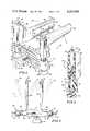
- FIG. 1is a perspective view of an apparatus constructed in accordance with the present invention
- FIG. 2is a fragmentary cross-sectional view of the apparatus of FIG. 1 taken generally along section lines 2--2 of FIG. 1;
- FIG. 3is a top plan view of the apparatus of FIG. 1;
- FIG. 4is a fragmentary cross-sectional view of the apparatus of FIG. 1 taken generally along section lines 4--4 of FIG. 1;
- FIG. 5is an exploded fragmentary perspective view of a detail of the apparatus shown in the cross-sectional view of FIGS. 1-4;
- FIG. 6is a perspective view of a detail of an alternative structure to that illustrated in FIGS. 1-4;
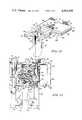
- FIG. 7is a perspective view of another apparatus constructed according to the present invention.
- FIG. 8is a fragmentary sectional view of the apparatus of FIG. 7, taken generally along section lines 8--8 thereof;
- FIG. 9is a partly fragmentary elevational view of another alternative structure to those illustrated in FIGS. 1-5 and 7-8;
- FIG. 10is a top plan view, partly fragmentary, taken along section lines 10--10 of FIG. 9;
- FIG. 11is a fragmentary end elevational view, taken generally along section lines 11--11 of FIG. 9;
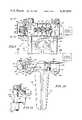
- FIG. 12is a perspective view of another alternative structure
- FIG. 13is a sectional view of the apparatus of FIG. 12, taken generally along section lines 13--13 thereof;
- FIG. 14is a partly fragmentary perspective view of another alternative structure.
- FIG. 15is a partly fragmentary perspective view of yet another alternative structure.
- a speculum 10includes a base 12 having first and second members 14 and 20, respectively, adjustably coupled to each other.
- First member 14includes a hollow interior 16.
- a slot 15is formed in first member 14 as shown, with a series of gear teeth 17 situated along a surface of the slot 15.
- Second member 20includes a portion 22 longitudinally movably received within the interior 16 of the first member 14.
- a crown gear-like ring 52has been provided on the underside of each of base members 14, 20.
- the rings 52may be attached to the base members 14 and 20 by any suitable means or may be formed with the base members 14 and 20 themselves. The purpose of rings 52 will be explained subsequently.
- the base 12further includes means 26 rotatably coupled to portion 22 of base member 20 for incrementally adjusting the distance between the distal portions 18 and 24 of the base members 14 and 20 respectively.
- Incremental adjusting means 26includes a spur gear 28 fixed to a rotatable shaft 30.
- a knob 32is attached to shaft 30 for rotation by the speculum operator to rotate gear 28.
- the spur gear 28includes a plurality of teeth which engage teeth 17 situated along the surface of slot 15 in base member 14. When the speculum operator rotates the knob 32, the distal portions 18 and 24 of the base members 14 and 20, respectively, are adjusted to a desired separation.
- the spur gear 28can be formed separately from, or formed on, the knob 32.
- the incremental adjusting means 26further includes means 40 for maintaining a desired separation between the distal ends 18 and 24 of the base members 14 and 20.
- means 40includes a rib 44 situated on the back side of spur gear 28 which engages one of two slots 42 formed in portion 22 of base member 20. By engaging rib 44 in one of slots 42, spur gear 28 is prevented from further rotation until the speculum operator desires to change the distance between the distal portions 18 and 24 of base members 14 and 20.
- a head 34is provided on the end of shaft 30 opposite knob 32. Head 34 is located in a recess 39 in member 20. Head 34 retains a spring washer 36.
- the speculum operatordisengages rib 44 from a slot 42 by pulling hand grip 32 outward and engages rib 44 in a slot 42 by releasing the hand grip 32.
- the speculum operatoris thus capable of incrementally adjusting the distance between the distal portions 18 and 24 of base members 14 and 20, respectively, and upon adjustment to a desired distance the speculum operator releases the hand grip 32 to sustain the desired distance until further adjustment is desired.
- more than one rib 44 and more than two slots 42could be provided.
- speculum 10further includes two elongated shafts 56 which are rotatably mounted in base members 14 and 20 at their distal portions 18 and 24 respectively. As illustrated in FIG. 2, the shafts 56 extend through apertures 21 located in the distal portions 18 and 24 and into the members 50.
- the members 40have crown gear teeth 53 provided in their surfaces adjacent the rings 52. Engagement of teeth 53 with respective rings 52 prevents the shafts 56 from rotating in member 14, 20 from selected rotational positions.
- alternative means 54may be provided instead of rings 52 and cooperating teeth 53 to prevent shaft 56 rotation with respect to members 14, 20.
- the alternative means 54is provided for each base member 14 and 20 for sustaining a rotational position of shafts 56 once the speculum operator has independently rotated the shafts to desired rotational positions.
- the alternative means 54 in FIGS. 1 and 2are thumbscrews threaded into apertures located in the base members 20 and 14. By advancing screws 54, the shafts 56 are engaged, thereby preventing rotational motion until desired by the speculum operator.
- Means 54are shown for purposes of illustration only in the embodiment of FIGS. 1, 2. Means 54 are not necessary to the proper operation of that embodiment. It will be understood that other known means could be utilized for sustaining rotational positions of shafts 56.
- Two members 62are provided for dilating or enlarging an incision, orifice, or meatus.
- Each member 62has a distal end 64 for contacting and restraining a portion of the orifice and a proximal end 66 detachably engaging a portion of the elongated rotatable shaft 56.
- Each member 62also includes a shoulder 63 adjacent its proximal end 66. Shoulders 63 rest against external body surfaces to support the speculum 10 away from the external body surfaces and prevent, to the greatest possible extent, contamination of the speculum members 14, 20, 56 by organisms on such external surfaces.
- edges 69 of the members 62are beaded, or rounded, to remove any sharp edges from them and minimize the likelihood of tissue damage from edges 69.
- the elongated rotatable shafts 56are engaged in sockets 67 provided on the proximal ends 66 of members 62 to mount the members 62 on the distal portions 18 and 24 of base members 14 and 20, respectively.
- Each member 62is elongated, has a concave inner surface 70, and has disposed on the concave inner surface 70 two elongated ribs 72, each of which includes an aperture 74 extending the length of the rib 72.
- Light from an external light sourcemay be directed along the ribs 72 and down the concave inner surfaces 70 of members 62 directly into the orifice or incision. Since members 62 are detachable from the shafts 56, various other shapes and sizes of members 62, such as is illustrated in FIG. 6, may be used with the speculum 10 depending upon the size, shape, or depth of the orifice, incision or meatus desired to be dilated.
- members 62may have at least their distal ends 64 covered with a layer of some material (not shown) which is capable of absorbing body fluids such as blood, and may be removed and either sterilized or disposed of after each use without disposing of the entire speculum 10. Accordingly, members 62 may be fabricated from any desirable material such as metal, plastic, etc. Preferably, members 62 will be constructed from a transparent plastic to permit light transmission through them and to permit an examiner to view the walls of the orifice or incision through them.
- the portions of rotatable shafts 56 which are engaged by the detachable members 62include means 60 on the shafts 56 for preventing members 62 from rotating about shafts 56.
- Means 60includes a rectangular portion 61 of each shaft 56. Rectangular portions 61 extend through the sockets 67 in the proximal ends 66 of members 62.
- Spring washers 58are interposed between the rectangular portions 61 of shafts 56 and the respective base members 14 and 20 to urge rectangular portions 61 away from members 14, 20 and teeth 53 into engagement with rings 52.
- Means 68are coupled to the proximal ends 66 of members 62 for sustaining desired positions of the members 62 along the shafts 56.
- the sustaining means 68include thumbscrews in the apertures located in the proximal ends 66 of members 62. By advancing thumbscrews 68, the extended rectangular portion of shaft 56 is engaged, fixing the positions of the members 62 along the shafts 56.
- members 62may be independently rotatably adjusted through various angles and sustained at various positions along their respective shafts 56 independently of each other, permitting the speculum operator the flexibility to adjust the speculum 10 to accommodate various types and shapes of orifices.
- the speculum operatorcan make several adjustments to the speculum 10 in order to adapt the speculum 10 to various sizes, shapes and depths of orifices to be enlarged and/or examined. Means are provided for sustaining the various adjusted positions of the speculum 10 during the examination process, leaving the speculum operator's hands free to perform necessary functions.
- the speculum operatorselects from various shapes and sizes of members 62 the type which is suitable for the orifice to be dilated. The two members 62 may be selected independently and therefore do not necessarily have to be of the same size and shape themselves.
- the members 62may be independently positioned on the shafts 56. Once the speculum operator has selected and attached the desired members 62, the distance between the proximal ends 66 of the members 62 may be incrementally adjusted to permit unobstructed access to the orifice after it is enlarged. This incremental adjustment is accomplished by pulling knob 32 outward and rotating it. As soon as a desired relationship is attained, the speculum operator releases the knob 32, spring washer 36 causing rib 44 to engage one of grooves 42 (FIG. 5) to lock members 14, 20 in a desired relative orientation.
- the distal ends 64 of members 62may be positioned independently of the positioning of the proximal ends 66 of members 62 by rotating shafts 56. This is achieved by pulling downwardly on knobs 50 against the urging of spring washers 58 (FIGS. 1, 2 and 4) to disengage teeth 53 from rings 52. The knobs 50 are rotated until the shafts 56 reach the desired positions. The knobs 50 are released to permit spring washers 58 to reengage teeth 53 with rings 52.
- the members 62may be rotated to a position 72 (FIG. 3) wherein the distal ends 64 are in contact with each other, facilitating the initial entry.
- the members 62may be independently rotated by rotating knobs 50, to positions 74 and 76 in which the orifice is enlarged or dilated to a desired width. It is important to note that the inital dilation of the orifice may be accomplished independent of any adjustment of the proximal ends 66 of members 62. In the embodiment utilizing thumbscrews 54 instead of rings 52 and teeth 53, once the desired rotational positions of members 62 have been established, the position of each member 62 may be independently locked by a thumbscrew 54. After the initial dilation of the orifice has been achieved, the distance between the proximal ends 66 of members 62 may be further incrementally increased in order to widen further the dilation or may be incrementally decreased in order to lessen the dilation.
- FIGS. 7-8those components performing the same or similar functions as the corresponding elements in the embodiment of FIGS. 1 ⁇ 6 are numbered similarly.
- the speculum 10includes base 12 having first and second members 14 and 20, respectively, adjustably coupled to each other.
- First member 14includes hollow interior 16.
- Second member 20includes a portion 22 longitudinally movably received within the interior 16 of the first member 14.
- a pin 53is formed on each member 50.
- a plurality of pockets 52are provided in each member 14, 20 to receive the pins 53 in each of various selected orientations of the contacting members 62 in this embodiment.
- the pins 53are urged upward into engagement with pockets 52 in this embodiment by coil springs 58.
- the base 12further includes means 26 rotatably engaging portion 22 of base member 20 for incrementally adjusting the distance between the distal portions 18 and 24 of the base members 14 and 20, respectively.
- Incremental adjusting means 26 in this embodimentincludes a threaded shaft 28 rotatably engaged in the end 18 of base member 14.
- Threaded shaft 28includes a knob 32 rotatable by the speculum operator to rotate shaft 28.
- the shaft threadsengage a bearing 17 which is situated in a bore 115 in the base member 14 and spring loaded into engagement with the troughs in the threads of shaft 28 by a coil spring 116 which is captured between the bearing 17 and a threaded plug 117.
- a light sourcemay be coupled to the members 62 through a fiber optic material, such as flexible glass fiber or one of certain types of acrylic resins, such as polymethylmethacrylate.
- the light source and optical waveguideare constructed as an attachment to a speculum of the type described herein, which may be used as a plastic vaginal speculum or proctoscope, or an abdominal retractor.
- each contacting member 62is provided with a socket 74 adjacent its respective shaft 56.
- Sockets 74are adapted to receive light sources 122.
- the light source 122 shown in FIG. 8includes lamp bulb 124 which extends into the socket 74, a bulb receptacle 126 and wires 128 connecting receptacle 126 to a power source (not shown).
- the light sourcecould be battery operated.
- Light from the lamp bulb 124is guided to the distal end 64 of its respective member 62 by the material from which member 62 itself is constructed.
- suitable materials having optical wave guiding propertiesare known. Among them is polymethylmethacrylate (LUCITE or PLEXIGLAS).
- Light from source 122is directed by the configuration of the material in member 62 down the concave inner surfaces 70 of members 62 directly into the orifice or incision.
- the operator of the speculum of FIGS. 7 and 8can make several adjustments to the speculum 10 in order to adapt the speculum 10 to various sizes, shapes, and depths of orifices to be enlarged and/or examined.
- the speculum operatorselects from various shapes and sizes of members 62 the type which is suitable for the orifice to be dilated.
- the distance between the proximal ends 66 of the members 62may be adjusted to permit unobstructed access to the orifice after it is enlarged. This adjustment is accomplished by rotating knob 32.
- the distal ends 64 of members 62may be positioned independently of the positioning of the proximal ends 66 of members 62 by pulling knobs 50 downward against the urging of coil springs 58 to move pins 53 from pockets 52 and rotating knobs 50. Once desired rotational positions of members 62 have been established, the position of each member 62 may be independently locked by releasing knobs 50 to reengage pins 53 and pockets 52.
- FIGS. 9-11those components performing the same or similar functions as the corresponding elements in the embodiments of FIGS. 1-6 and 7-8 are numbered similarly.
- the speculum 10includes a base 12 having first and second members 14, 20 respectively, adjustably coupled to each other.
- Each of the members 14, 20 in this embodimentis molded, e.g., from a synthetic plastic material, in two halves which are subsequently joined together.
- First member 14includes the hollow interior 16.
- Second member 20includes a portion 22 longitudinally movable within the interior 16.
- a locating pin 53is formed in each member 50, and a plurality of cooperating pockets 52 are provided on each of members 14, 20 to receive the locating pins in each of various selected orientations of the contacting members 62.
- the pinsare urged upwardly into engagement with the pockets of this embodiment by spring washers 58 interposed between the rectangular portions 61 of shafts 56 and the respective base members 14, 20.
- the base member 12 of this embodimentincludes, as incremental adjustment means 26, a threaded shaft 28 rotatably captured in the end 18 of base member 14 by a C-ring 130 provided in an annular groove 132 on a projecting bearing portion 134 of an adjustment knob 32.
- Knob 32is provided with a stop surface 136.
- the end 18 of base member 14is rotatably captured between the C-ring 130 and the surface 136.
- End 18 of base member 14is formed to provide a generally rectangular recess 140.
- An end cap 142has an open center 144 (FIG. 11) and an open end 146 (FIGS. 9-10) sized slidably to engage knob 32.
- Tabs 148are provided at the open end 146 to engage in the recess and hold the cap on end 18.
- the capincludes a longitudinally extending slot 150 (FIGS. 9, 11) in its sidewall 152. The edges of the slot 150 are grooved, as indicated at 154 (FIG. 11) to engage the splines 156 of knob 32.
- the knob 32is held in position by the engagement of the grooves 154 with the splines 156 when cap 142 is placed over the knob 32 and the tabs 148 are engaged in recess 140.
- the shaft 28threads engage in a threaded bore 115 provided in the base member 22.
- each contacting member 62is provided with a socket 74 adjacent its respective shaft 56.
- the sockets 74support lamps 122.
- Conductors 128connect the sources 122 to a power source (illustrated diagrammatically).
- FIGS. 12-13those elements performing the same or similar functions as the corresponding elements in the embodiments of FIGS. 1-5, 7-8 and 9-11 are numbered similarly.
- first member 14is constructed from, for example, moldable plastic material.
- First member 14is constructed in the form of a case having a hollow interior 160. Slots 162 are provided in two opposite walls 164, 166 of the case 14.
- Member 20(FIG. 13) is constructed in the form of a slide movably mounted in the interior 160.
- a pin 53is formed on each of the knob members 50.
- a plurality of pockets 52are provided in member 14 adjacent the knob 50 at end 18 to receive pin 53 of that knob 50 in each of various selected orientations of the contacting members 62.
- the pin 53is urged into engagement with the pocket 52 by a coil spring 58 which is provided in a cavity 168 in first member 14 adjacent end 18.
- the coil spring 58works against a pin 170 protruding from the shaft 56 rotatably mounted in end 18.
- a similar arrangement for the knob member 50 and shaft 56is provided on member 20, with a cavity 168 for the spring 58.
- the spring 58works against a pin 170 which protrudes from shaft 56.
- a plurality of pins 53are provided on knob member 50 which are adapted for insertion into the slot 162 in wall 164.
- One of pins 53selectively engages the slot 162 to prevent rotation of the member 50, and thereby the shaft 56 and contacting member 62 associated with member 20.
- the member 14 wall 164has a reduced thickness, as illustrated at 172 in FIG. 13, around the slot 162 in wall 164. This configuration permits free sliding movement of member 20 without interference between the slot 162 or wall 164 and pins 53 on the member 20 knob 50.
- Member 20is further provided with a rigidly attached, longitudinally extending threaded shaft 28.
- Shaft 28rotatably mounts a knob 32 with a threaded central bore 174.
- Knob 32 in this embodimentis rotatably mounted in the case-like first member 14 between two end supports 176, with the end supports providing bearing surfaces 178 and the knob 32 providing cooperating bearing surfaces 180.
- Knob 32is accessible through an opening 182 in one of the molded halves of base member 14. Rotation of the knob in a first direction, indicated by arrow 186 (FIG. 12) on member 14, results in movement of second member 20, and its contacting member 62 toward the end 186 of first member 14. Rotation of knob 32 in a second direction, indicated by arrow 188 on member 14, causes member 20 to move toward end 18 of member 14.
- the shafts 56are provided with permanently mounted portions 192 including sockets 74 adapted to receive the light sources 122, and conductors 128 which are threaded or molded into the shaft portions 192.
- the conductors 128extend into the interior 160 of member 14 where they are connected through a switch 194 to a dry cell 196.
- the contacting members 62 in this arrangementare adapted to fit slidably and snugly over the square or rectangular ends 61 of shafts 56 above shaft portions 192.
- Each contacting member 62is provided with a lens portion 200 (FIG. 12) which is in intimate contact with the lamp bulb 124 provided in a respective socket 74 when the contacting members 62 are in position on the shaft 56 ends, as illustrated in FIG. 12.
- the lamps 122are permanently mounted on the speculum 10, and need not be removed from, or replaced in, lamp sockets 74 each time the contacting members 62 are changed.
- FIGS. 14-15those elements performing the same or similar functions as the corresponding elements in the embodiments of FIGS. 1-5, 7-8, 9-11 and 12-13 are numbered similarly.
- the slot 15 formed in first member 14has two opposite edges, each provided with a shallow, longitudinally extending groove 210.
- a tab 214is constructed from a flexible, semi-rigid synthetic material, such as nylon.
- Tab 214has opposite longitudinally extending tongues 216 (only one of which is shown) for engagement with the grooves 210 as the tab 214 is slidably inserted into the slot 15 to rest against the end 218 of the slot 15.
- the tab 214is provided with a transversely extending tooth or pawl 222 on its side facing the hollow interior 16.
- Base member 20includes a series of transversely extending ratchet teeth 224 on its side 226 facing the slot 15.
- the tongues 216 on tab 214terminate adjacent pawl 212 such that an outward pull on a portion 228 of tab 214 moves pawl 222 clear of engagment with ratchet teeth 224.
- Adjustmentis made of the distance between the shafts 56 mounted on respective members 14, 20 by disengaging pawl 222 from the teeth 224 and manually sliding member 20 to a desired projection from member 14.
- Pawl 222is then pushed into engagement with a ratchet tooth 224 to retain members 14, 20 in the selected projected orientations.
- member 20is constructed as in the embodiment of FIG. 14 with a series of ratchet teeth 224 on its side 226 facing an opening 230 in member 14.
- a tab 232is mounted in the opening 230 by engagement of a pair of ears 234 in slots 236 which intersect opening 230.
- Tab 232is thereby pivotally mounted about ears 234 in the opening 230.
- the inner side 242 of tab 232is provided with a transversely extending concave, or hollow, region 244.
- the tab 232is constructed from the same type of flexible synthetic material as tab 214 in FIG. 14.
Landscapes
- Health & Medical Sciences (AREA)
- Life Sciences & Earth Sciences (AREA)
- Surgery (AREA)
- Nuclear Medicine, Radiotherapy & Molecular Imaging (AREA)
- Biomedical Technology (AREA)
- Optics & Photonics (AREA)
- Pathology (AREA)
- Radiology & Medical Imaging (AREA)
- Biophysics (AREA)
- Engineering & Computer Science (AREA)
- Physics & Mathematics (AREA)
- Heart & Thoracic Surgery (AREA)
- Medical Informatics (AREA)
- Molecular Biology (AREA)
- Animal Behavior & Ethology (AREA)
- General Health & Medical Sciences (AREA)
- Public Health (AREA)
- Veterinary Medicine (AREA)
- Endoscopes (AREA)
Abstract
Description
This is a continuation-in-part of my copending United States Patent Application Ser. No. 901,521 filed May 1, 1978, now U.S. Pat. No. 4,156,424.
The present invention relates generally to an apparatus for dilating a meatus, orifice or incision and more particularly to a speculum which provides means for independently adjusting the distances between the proximal and distal ends of detachable restraining members used to dilate the meatus, orifice or incision and means for sustaining various desired distances between both the distal and proximal ends thereby leaving the speculum operator's hands free for purposes of examination or other activities.
There are many known specula and forceps for enlarging body orifices or incisions for such purposes as examination or surgery. However, many of these devices are not adaptable for use in orifices or incisions having different sizes, shapes, depths and so forth; have limited adjustment capability; and have the means for adjustment situated such that the view and/or ability of the user to examine the orifice is at least partially obstructed. The following are illustrative U.S. Pat. Nos.: Molesworth, 400,589; Crockett, 776,302; Joutras, 1,094,575; Radcliff, 2,217,968; Batista, 3,853,120; Marco, 2,544,932; Moore et al, 3,716,047; Moore et al, 3,890,961; Smith, 1,706,500; Rose, 3,196,865; Crossley, 1,230,873; Sheaff, 1,222,478; Pitt, 605,652; and Gentile, French Patent Specification No. 473,451. See also SURGERY, GYNECOLOGY AND OBSTETRICS, Vol., 68, No. 6, Jan. 1939, pp. 1060-63; Fogerty et al, U.S. Pat. No. 3,503,398; Galiano, U.S. Pat. No. 399,749; Bernardot, French Patent Specification No. 641,915; and Raffaele, Italian Patent Specification No. 246,611. Furthermore, many prior devices require that the user maintain a constant physical force in order to restrain the orifice once it has been enlarged. See for example Pomerene, U.S. Pat. No. 1,170,324.
In copending applications, Ser. No. 811,550, filed June 30, 1977, now U.S. Pat. No. 4,165,746, and Ser. No. 958,795, filed Nov. 8, 1978, both entitled "Plastic Forceps", I have disclosed solutions to some of the aforementioned problems associated with prior specula or forceps. It is believed that the improved speculum provided by the present invention provides solutions to all of the problems mentioned hereinabove by providing a high degree of flexibility and various self-sustaining features.
In accordance with the present invention, an adjustable speculum is provided. The speculum is adaptable for use in enlarging and holding open orifices, incisions and the like of various sizes, shapes and depths. The speculum allows the user substantially unobstructed access to the orifice for examination and various other functions.
According to the invention, a speculum includes a pair of members for restraining and dilating an orifice, incision or the like. Each restraining member has a distal end for contacting the walls of the orifice and a proximal end for detachably engaging a shaft, and a base supporting the shafts and including means for adjusting the distance between the shafts whereby the distance between the proximal ends of the restraining members is independently adjustable.
Further according to the invention, in such a speculum, the shafts are rotatably coupled to the base and include means fixed to each shaft for preventing the dilating members from rotating on the shafts. The distance between the distal ends of the dilating members is rotatably adjustable independent of adjustments to the proximal ends of the dilating members.
Additionally according to the invention, the speculum includes means for independently sustaining desired distances between the distal and proximal ends of the dilating members and desired positions of the dilating members along the shafts.
Another feature of the present invention is to provide a speculum having detachable dilating members which may be of various sizes or shapes and which may be either separately sterilized or disposed of after each use.
Various features and advantages of the present invention will be apparent from the following detailed description of an embodiment thereof. The description can best be understood by reference to the accompanying drawings which illustrate the invention.
FIG. 1 is a perspective view of an apparatus constructed in accordance with the present invention;
FIG. 2 is a fragmentary cross-sectional view of the apparatus of FIG. 1 taken generally alongsection lines 2--2 of FIG. 1;
FIG. 3 is a top plan view of the apparatus of FIG. 1;
FIG. 4 is a fragmentary cross-sectional view of the apparatus of FIG. 1 taken generally alongsection lines 4--4 of FIG. 1;
FIG. 5 is an exploded fragmentary perspective view of a detail of the apparatus shown in the cross-sectional view of FIGS. 1-4;
FIG. 6 is a perspective view of a detail of an alternative structure to that illustrated in FIGS. 1-4;
FIG. 7 is a perspective view of another apparatus constructed according to the present invention;
FIG. 8 is a fragmentary sectional view of the apparatus of FIG. 7, taken generally along section lines 8--8 thereof;
FIG. 9 is a partly fragmentary elevational view of another alternative structure to those illustrated in FIGS. 1-5 and 7-8;
FIG. 10 is a top plan view, partly fragmentary, taken alongsection lines 10--10 of FIG. 9;
FIG. 11 is a fragmentary end elevational view, taken generally alongsection lines 11--11 of FIG. 9;
FIG. 12 is a perspective view of another alternative structure;
FIG. 13 is a sectional view of the apparatus of FIG. 12, taken generally alongsection lines 13--13 thereof;
FIG. 14 is a partly fragmentary perspective view of another alternative structure; and
FIG. 15 is a partly fragmentary perspective view of yet another alternative structure.
Referring particularly to FIG. 1, aspeculum 10 includes abase 12 having first andsecond members First member 14 includes ahollow interior 16. Aslot 15 is formed infirst member 14 as shown, with a series ofgear teeth 17 situated along a surface of theslot 15.Second member 20 includes aportion 22 longitudinally movably received within theinterior 16 of thefirst member 14. As illustrated in FIG. 1, a crown gear-like ring 52 has been provided on the underside of each ofbase members rings 52 may be attached to thebase members base members rings 52 will be explained subsequently.
Thebase 12 further includesmeans 26 rotatably coupled toportion 22 ofbase member 20 for incrementally adjusting the distance between thedistal portions base members spur gear 28 fixed to arotatable shaft 30. Aknob 32 is attached toshaft 30 for rotation by the speculum operator to rotategear 28. Thespur gear 28 includes a plurality of teeth which engageteeth 17 situated along the surface ofslot 15 inbase member 14. When the speculum operator rotates theknob 32, thedistal portions base members spur gear 28 can be formed separately from, or formed on, theknob 32.
Referring to FIGS. 4 and 5, the incremental adjusting means 26 further includes means 40 for maintaining a desired separation between thedistal ends base members rib 44 situated on the back side ofspur gear 28 which engages one of twoslots 42 formed inportion 22 ofbase member 20. By engagingrib 44 in one ofslots 42,spur gear 28 is prevented from further rotation until the speculum operator desires to change the distance between thedistal portions base members
As illustrated in FIG. 4, a head 34 is provided on the end ofshaft 30opposite knob 32. Head 34 is located in arecess 39 inmember 20. Head 34 retains aspring washer 36. The speculum operator disengagesrib 44 from aslot 42 by pullinghand grip 32 outward and engagesrib 44 in aslot 42 by releasing thehand grip 32. The speculum operator is thus capable of incrementally adjusting the distance between thedistal portions base members hand grip 32 to sustain the desired distance until further adjustment is desired. Of course, more than onerib 44 and more than twoslots 42 could be provided.
Referring again to FIGS. 1 and 2,speculum 10 further includes twoelongated shafts 56 which are rotatably mounted inbase members distal portions shafts 56 extend throughapertures 21 located in thedistal portions members 50. Themembers 40 havecrown gear teeth 53 provided in their surfaces adjacent therings 52. Engagement ofteeth 53 withrespective rings 52 prevents theshafts 56 from rotating inmember
If continuous, rather than discrete adjustment ofshafts 56 inmembers rings 52 and cooperatingteeth 53 to preventshaft 56 rotation with respect tomembers base member shafts 56 once the speculum operator has independently rotated the shafts to desired rotational positions. The alternative means 54 in FIGS. 1 and 2 are thumbscrews threaded into apertures located in thebase members screws 54, theshafts 56 are engaged, thereby preventing rotational motion until desired by the speculum operator. Means 54 are shown for purposes of illustration only in the embodiment of FIGS. 1, 2. Means 54 are not necessary to the proper operation of that embodiment. It will be understood that other known means could be utilized for sustaining rotational positions ofshafts 56.
Twomembers 62 are provided for dilating or enlarging an incision, orifice, or meatus. Eachmember 62 has adistal end 64 for contacting and restraining a portion of the orifice and aproximal end 66 detachably engaging a portion of the elongatedrotatable shaft 56. Eachmember 62 also includes a shoulder 63 adjacent itsproximal end 66. Shoulders 63 rest against external body surfaces to support thespeculum 10 away from the external body surfaces and prevent, to the greatest possible extent, contamination of thespeculum members edges 69 of themembers 62 are beaded, or rounded, to remove any sharp edges from them and minimize the likelihood of tissue damage from edges 69. The elongatedrotatable shafts 56 are engaged insockets 67 provided on the proximal ends 66 ofmembers 62 to mount themembers 62 on thedistal portions base members
Eachmember 62 is elongated, has a concaveinner surface 70, and has disposed on the concaveinner surface 70 twoelongated ribs 72, each of which includes anaperture 74 extending the length of therib 72. Light from an external light source (not shown) may be directed along theribs 72 and down the concaveinner surfaces 70 ofmembers 62 directly into the orifice or incision. Sincemembers 62 are detachable from theshafts 56, various other shapes and sizes ofmembers 62, such as is illustrated in FIG. 6, may be used with thespeculum 10 depending upon the size, shape, or depth of the orifice, incision or meatus desired to be dilated. Furthermore,members 62 may have at least theirdistal ends 64 covered with a layer of some material (not shown) which is capable of absorbing body fluids such as blood, and may be removed and either sterilized or disposed of after each use without disposing of theentire speculum 10. Accordingly,members 62 may be fabricated from any desirable material such as metal, plastic, etc. Preferably,members 62 will be constructed from a transparent plastic to permit light transmission through them and to permit an examiner to view the walls of the orifice or incision through them.
As further illustrated in FIGS. 1 and 2, the portions ofrotatable shafts 56 which are engaged by thedetachable members 62 include means 60 on theshafts 56 for preventingmembers 62 from rotating aboutshafts 56.Means 60 includes arectangular portion 61 of eachshaft 56.Rectangular portions 61 extend through thesockets 67 in the proximal ends 66 ofmembers 62.Spring washers 58 are interposed between therectangular portions 61 ofshafts 56 and therespective base members rectangular portions 61 away frommembers teeth 53 into engagement withrings 52.
Means 68 are coupled to the proximal ends 66 ofmembers 62 for sustaining desired positions of themembers 62 along theshafts 56. The sustaining means 68 include thumbscrews in the apertures located in the proximal ends 66 ofmembers 62. By advancingthumbscrews 68, the extended rectangular portion ofshaft 56 is engaged, fixing the positions of themembers 62 along theshafts 56. It should be noted thatmembers 62 may be independently rotatably adjusted through various angles and sustained at various positions along theirrespective shafts 56 independently of each other, permitting the speculum operator the flexibility to adjust thespeculum 10 to accommodate various types and shapes of orifices.
Having thus described in detail an embodiment of the invention, the operation ofspeculum 10 will now be described by referring to FIGS. 1, 3 and 4. The speculum operator can make several adjustments to thespeculum 10 in order to adapt thespeculum 10 to various sizes, shapes and depths of orifices to be enlarged and/or examined. Means are provided for sustaining the various adjusted positions of thespeculum 10 during the examination process, leaving the speculum operator's hands free to perform necessary functions. The speculum operator selects from various shapes and sizes ofmembers 62 the type which is suitable for the orifice to be dilated. The twomembers 62 may be selected independently and therefore do not necessarily have to be of the same size and shape themselves. Furthermore, as has previously been described, themembers 62 may be independently positioned on theshafts 56. Once the speculum operator has selected and attached the desiredmembers 62, the distance between the proximal ends 66 of themembers 62 may be incrementally adjusted to permit unobstructed access to the orifice after it is enlarged. This incremental adjustment is accomplished by pullingknob 32 outward and rotating it. As soon as a desired relationship is attained, the speculum operator releases theknob 32,spring washer 36 causingrib 44 to engage one of grooves 42 (FIG. 5) to lockmembers
As illustrated by FIG. 3, the distal ends 64 ofmembers 62 may be positioned independently of the positioning of the proximal ends 66 ofmembers 62 by rotatingshafts 56. This is achieved by pulling downwardly onknobs 50 against the urging of spring washers 58 (FIGS. 1, 2 and 4) to disengageteeth 53 fromrings 52. Theknobs 50 are rotated until theshafts 56 reach the desired positions. Theknobs 50 are released to permitspring washers 58 to reengageteeth 53 withrings 52. Upon initial entry and contact with the walls of the orifice to be dilated (not shown), themembers 62 may be rotated to a position 72 (FIG. 3) wherein the distal ends 64 are in contact with each other, facilitating the initial entry. After entry, themembers 62 may be independently rotated by rotatingknobs 50, topositions members 62. In theembodiment utilizing thumbscrews 54 instead ofrings 52 andteeth 53, once the desired rotational positions ofmembers 62 have been established, the position of eachmember 62 may be independently locked by athumbscrew 54. After the initial dilation of the orifice has been achieved, the distance between the proximal ends 66 ofmembers 62 may be further incrementally increased in order to widen further the dilation or may be incrementally decreased in order to lessen the dilation.
Referring to the embodiment of the invention illustrated in FIGS. 7-8, those components performing the same or similar functions as the corresponding elements in the embodiment of FIGS. 1≠6 are numbered similarly.
In FIG. 7, thespeculum 10 includesbase 12 having first andsecond members First member 14 includeshollow interior 16.Second member 20 includes aportion 22 longitudinally movably received within theinterior 16 of thefirst member 14. As illustrated in FIG. 7, apin 53 is formed on eachmember 50. A plurality ofpockets 52 are provided in eachmember pins 53 in each of various selected orientations of the contactingmembers 62 in this embodiment. Thepins 53 are urged upward into engagement withpockets 52 in this embodiment by coil springs 58.
The base 12 further includesmeans 26 rotatably engagingportion 22 ofbase member 20 for incrementally adjusting the distance between thedistal portions base members shaft 28 rotatably engaged in theend 18 ofbase member 14. Threadedshaft 28 includes aknob 32 rotatable by the speculum operator to rotateshaft 28. The shaft threads engage abearing 17 which is situated in abore 115 in thebase member 14 and spring loaded into engagement with the troughs in the threads ofshaft 28 by acoil spring 116 which is captured between the bearing 17 and a threadedplug 117. When the speculum operator rotates theknob 32, thedistal portions base members shaft 28 is such that this adjustment will be maintained even under substantial load.
For the purpose of providing light, especially during certain types of surgical procedures, a light source may be coupled to themembers 62 through a fiber optic material, such as flexible glass fiber or one of certain types of acrylic resins, such as polymethylmethacrylate. The light source and optical waveguide are constructed as an attachment to a speculum of the type described herein, which may be used as a plastic vaginal speculum or proctoscope, or an abdominal retractor.
In the embodiment of FIGS. 7-8, each contactingmember 62 is provided with asocket 74 adjacent itsrespective shaft 56.Sockets 74 are adapted to receivelight sources 122. Thelight source 122 shown in FIG. 8 includeslamp bulb 124 which extends into thesocket 74, abulb receptacle 126 andwires 128 connectingreceptacle 126 to a power source (not shown). The light source could be battery operated. Light from thelamp bulb 124 is guided to thedistal end 64 of itsrespective member 62 by the material from whichmember 62 itself is constructed. Several suitable materials having optical wave guiding properties are known. Among them is polymethylmethacrylate (LUCITE or PLEXIGLAS). Light fromsource 122 is directed by the configuration of the material inmember 62 down the concaveinner surfaces 70 ofmembers 62 directly into the orifice or incision. As with the embodiment of FIGS. 1-6, the operator of the speculum of FIGS. 7 and 8 can make several adjustments to thespeculum 10 in order to adapt thespeculum 10 to various sizes, shapes, and depths of orifices to be enlarged and/or examined. The speculum operator selects from various shapes and sizes ofmembers 62 the type which is suitable for the orifice to be dilated. The distance between the proximal ends 66 of themembers 62 may be adjusted to permit unobstructed access to the orifice after it is enlarged. This adjustment is accomplished by rotatingknob 32.
The distal ends 64 ofmembers 62 may be positioned independently of the positioning of the proximal ends 66 ofmembers 62 by pullingknobs 50 downward against the urging ofcoil springs 58 to movepins 53 frompockets 52 androtating knobs 50. Once desired rotational positions ofmembers 62 have been established, the position of eachmember 62 may be independently locked by releasingknobs 50 to reengagepins 53 and pockets 52.
The embodiments and methods of operation described hereinabove are not to be construed as excluding other embodiments or modes of operation of thespeculum 10.
The construction illustrated, with thebase members
Referring to the embodiment of the invention illustrated in FIGS. 9-11, those components performing the same or similar functions as the corresponding elements in the embodiments of FIGS. 1-6 and 7-8 are numbered similarly.
In FIGS. 9-11, thespeculum 10 includes a base 12 having first andsecond members members First member 14 includes thehollow interior 16.Second member 20 includes aportion 22 longitudinally movable within the interior 16.
In this embodiment, as in the embodiment illustrated in FIGS. 7-8, a locatingpin 53 is formed in eachmember 50, and a plurality of cooperatingpockets 52 are provided on each ofmembers members 62. The pins are urged upwardly into engagement with the pockets of this embodiment byspring washers 58 interposed between therectangular portions 61 ofshafts 56 and therespective base members
Thebase member 12 of this embodiment includes, as incremental adjustment means 26, a threadedshaft 28 rotatably captured in theend 18 ofbase member 14 by a C-ring 130 provided in anannular groove 132 on a projectingbearing portion 134 of anadjustment knob 32.Knob 32 is provided with astop surface 136. Theend 18 ofbase member 14 is rotatably captured between the C-ring 130 and thesurface 136.
Theshaft 28 threads engage in a threadedbore 115 provided in thebase member 22. When the speculum operator rotates theknob 32, thedistal portions base members
For the purpose of providing light, each contactingmember 62 is provided with asocket 74 adjacent itsrespective shaft 56. Thesockets 74support lamps 122.Conductors 128 connect thesources 122 to a power source (illustrated diagrammatically).
Referring now to the embodiment of the invention illustrated in FIGS. 12-13, those elements performing the same or similar functions as the corresponding elements in the embodiments of FIGS. 1-5, 7-8 and 9-11 are numbered similarly.
In this embodiment,first member 14 is constructed from, for example, moldable plastic material.First member 14 is constructed in the form of a case having ahollow interior 160.Slots 162 are provided in twoopposite walls case 14. Member 20 (FIG. 13) is constructed in the form of a slide movably mounted in theinterior 160. Apin 53 is formed on each of theknob members 50. A plurality ofpockets 52 are provided inmember 14 adjacent theknob 50 atend 18 to receivepin 53 of thatknob 50 in each of various selected orientations of the contactingmembers 62. Thepin 53 is urged into engagement with thepocket 52 by acoil spring 58 which is provided in acavity 168 infirst member 14adjacent end 18. Thecoil spring 58 works against apin 170 protruding from theshaft 56 rotatably mounted inend 18.
A similar arrangement for theknob member 50 andshaft 56 is provided onmember 20, with acavity 168 for thespring 58. Thespring 58 works against apin 170 which protrudes fromshaft 56. To prevent rotation of theshaft 56 associated withsecond member 20, a plurality ofpins 53 are provided onknob member 50 which are adapted for insertion into theslot 162 inwall 164. One ofpins 53 selectively engages theslot 162 to prevent rotation of themember 50, and thereby theshaft 56 and contactingmember 62 associated withmember 20. To prevent interference between theother pins 53 associated withsecond member 20, themember 14wall 164 has a reduced thickness, as illustrated at 172 in FIG. 13, around theslot 162 inwall 164. This configuration permits free sliding movement ofmember 20 without interference between theslot 162 orwall 164 and pins 53 on themember 20knob 50.
Theshafts 56 are provided with permanently mountedportions 192 includingsockets 74 adapted to receive thelight sources 122, andconductors 128 which are threaded or molded into theshaft portions 192. Theconductors 128 extend into theinterior 160 ofmember 14 where they are connected through aswitch 194 to adry cell 196. The contactingmembers 62 in this arrangement are adapted to fit slidably and snugly over the square or rectangular ends 61 ofshafts 56 aboveshaft portions 192. Each contactingmember 62 is provided with a lens portion 200 (FIG. 12) which is in intimate contact with thelamp bulb 124 provided in arespective socket 74 when the contactingmembers 62 are in position on theshaft 56 ends, as illustrated in FIG. 12. In this arrangement, thelamps 122 are permanently mounted on thespeculum 10, and need not be removed from, or replaced in,lamp sockets 74 each time the contactingmembers 62 are changed.
In the embodiments of the invention illustrated in FIGS. 14-15, those elements performing the same or similar functions as the corresponding elements in the embodiments of FIGS. 1-5, 7-8, 9-11 and 12-13 are numbered similarly.
In the embodiment of FIG. 14, theslot 15 formed infirst member 14 has two opposite edges, each provided with a shallow, longitudinally extendinggroove 210. Atab 214 is constructed from a flexible, semi-rigid synthetic material, such as nylon.Tab 214 has opposite longitudinally extending tongues 216 (only one of which is shown) for engagement with thegrooves 210 as thetab 214 is slidably inserted into theslot 15 to rest against theend 218 of theslot 15. Thetab 214 is provided with a transversely extending tooth orpawl 222 on its side facing thehollow interior 16.
In the embodiment of FIG. 15,member 20 is constructed as in the embodiment of FIG. 14 with a series ofratchet teeth 224 on itsside 226 facing anopening 230 inmember 14. In this embodiment, atab 232 is mounted in theopening 230 by engagement of a pair ofears 234 inslots 236 which intersect opening 230.Tab 232 is thereby pivotally mounted aboutears 234 in theopening 230. Theinner side 242 oftab 232 is provided with a transversely extending concave, or hollow,region 244. Thetab 232 is constructed from the same type of flexible synthetic material astab 214 in FIG. 14. It will be appreciated that pressure in theoutside surface 246 of thetab 232 opposite theregion 244 will result in an outward pivotal motion of thetab 232end 250 having thepawl 222. Such outward motion will result in disengagement of thepawl 222 from theratchet teeth 224 provided inmember 20 and permit sliding movement of themember 20 in theinterior 16 ofmember 14 for adjustment purposes. Releasing the pressure on thetab 232 oppositeconcave portion 244 permits thetab 232 to flex back about the pivotal mountingears 234 such thatpawl 222 returns into engagement with theratchet teeth 224, lockingmembers
Claims (18)
1. A speculum comprising a base including first and second base members for movement with respect to one another, means for adjustng the distance between a distal portion of the first base member and a distal portion of the second base member, means for connecting the adjusting means to one of the first and second base members, first and second shafts, means rotatably supporting each shaft from the distal portion of a respective one of the first and second members, and means for dilating an orifice, the dilating means being provided on the first and second shafts, the dilating means being responsive to adjustment of the first and second members and rotation of the first and second shafts, said means for adjusting the distance between the distal portions of the first and second members including a threaded shaft mounted in one of the first and second base members, means engaging the threaded shaft on the other of the first and second base members, and means for selectively rotating one of either the threaded shaft or means engaging the threaded shaft to advance and retract said other base member with respect to said one base member.
2. The apparatus of claim 1 wherein the threaded shaft is rotatably mounted with respect to one of the base members and the means engaging the threaded shaft is stationarily mounted with respect to the other of the base members.
3. The apparatus of claim 1 wherein the threaded shaft is stationarily mounted with respect to one of the base members and the means engaging the threaded shaft is rotatably mounted with respect to the other of the base members.
4. A speculum comprising a base including a first base member providing an interior and a second base member for movement within said interior, means for adjusting the distance between a distal portion of said first base member and a distal portion of said second base member, means for connecting said adjusting means to one of said base members, two shafts, means rotatably coupling each of the shafts to the distal portion of a respective base member, and means for dilating an orifice, the dilating means being provided on said shafts, said dilating means responsive to selective adjustment of said first and second base members and rotation of said elongated shafts selectively to dilate the orifice, said means for adjusting said distance between said distal portions of said first and second base members including a threaded shaft mounted on one of said base members and means for engaging said threaded shaft on the other of said base members, and means for selectively rotating one of either said threaded shaft or said means engaging said threaded shaft selectively to vary said distance.
5. The apparatus of claim 4 wherein said threaded shaft is rotatably mounted on said one of said base members and said means engaging said threaded shaft comprises a threaded passageway provided in said other of said base members.
6. The apparatus of claim 5 in which said one of said base members includes journal mounting means for rotatably mounting said threaded shaft.
7. The apparatus of claim 4 wherein said threaded shaft is stationarily mounted on said one of said base members and said means engaging said threaded shaft comprises means rotatably mounted on said other of said base members and including a threaded passageway engaging said threaded shaft.
8. The apparatus of claim 7 wherein said means for selectively rotating one of said shaft and means engaging said shaft includes a hand-manipulable wheel.
9. The apparatus of claim 8 wherein said threaded passageway is provided through the axis of said wheel.
10. A speculum comprising a base including first and second base members for movement with respect to one another, means for adjusting the distance between a distal portion of the first base member and a distal portion of the second base member, means for connecting the adjusting means to one of the first and second base members, first and second shafts, means rotatably supporting said first shaft from a distal portion of the first base member, means supporting said second shaft from a distal portion of the second base member, blade-like contacting members for dilating an orifice, the contacting members being provided on the first and second shafts, the contacting members being responsive to adjustment of the first and second base members and rotation of the first shaft, and means engageable with said first shaft for independently sustaining a desired rotational position of one of the contacting members associated with the first shaft, such position-sustaining means including a fixed projection on one of said first base member and first shaft and a plurality of sockets on the other of said first base member and first shaft, each socket sized to receive the projection, and spring means urging said projection and sockets together so as to urge the projection into engagement with a selected one of said sockets to prevent rotation of said first shaft with respect to said first base member.
11. The apparatus of claim 10 wherein the means for supporting said second shaft from a distal portion of the second base member includes means for rotatably supporting the second shaft from a distal portion of the second base member, and means engageable with the second shaft for independently sustaining a desired rotational position of the contacting member associated with the second shaft.
12. The apparatus of claim 11 wherein the means for independently sustaining the desired rotational position of the second shaft includes a fixed projection on one of the second shaft and second base member and a plurality of sockets on the other of the second shaft and second base member, each socket sized to receive the projection, and spring means urging said projection and sockets together so as to urge the projection into engagement with a selected one of said sockets to prevent rotation of the second shaft with respect to the second base member.
13. A speculum including at least two blade-like contacting members for dilating an orifice, a shaft for supporting each contacting member, means for connecting each contacting member to a respective shaft, each contacting member having a proximal end engaging a respective shaft and a distal end for insertion into the orifice, a base including means for rotatably supporting a first one of said shafts and for supporting the other of said shafts, and means for adjusting the distance between the distal ends of the contacting members including first means on the base and second means on said first one of the shafts engaging the first means in at least selected positions of said first one of the shafts to prevent rotation of said first one of the shafts with respect to said base, the base including a passageway for said first one of the shafts, said first one of the shafts being rotatably received in its passageway, the means on the base including a plurality of sockets on the base surrounding said passageway, and said second means including a fixed projection on said first one of the shafts, and means for yieldably urging said projection into engagement with a selected one of said sockets selectively to position said first one of the shafts with respect to said base.
14. A speculum comprising a base including first and second base members for movement with respect to one another, means for adjusting the distance between a distal portion of the first base member and a distal portion of the second base member, means for connecting the adjusting means to one of the first and second base members, first and second shafts, means rotatably supporting said first shaft from a distal portion of the first base member, means supporting said second shaft from a distal portion of the second base member, blade-like contacting members for dilating an orifice, the contacting members being provided on the first and second shafts and extending generally perpendicular to the first and second shafts, the contacting members being responsive to adjustment of the first and second base members and rotation of the first shaft, and means engageable with said first shaft for independently sustaining a desired rotational position of the contacting member associated with the first shaft, such position-sustaining means including a fixed projection on one of said first base member and first shaft and a plurality of sockets on the other of said first base member and first shaft, each socket sized to receive the projection, and spring means urging the projection into engagement with a selected one of said sockets to prevent rotation of said first shaft with respect to said first base member.
15. The apparatus of claim 14 wherein the means for supporting the first and second shafts includes means for supporting the shafts such that their axes are generally parallel and adjustment of the distance between the distal portions of the first and second base members adjusts the distance between the first and second shaft axes.
16. The apparatus of claim 14 wherein the means for supporting said second shaft from a distal portion of the second base member includes means for rotatably supporting the second shaft from a distal portion of the second base member, and means engageable with the second shaft for independently sustaining a desired rotational position of the contacting member associated with the second shaft.
17. The apparatus of claim 16 wherein the means for independently sustaining the desired rotational position of the second shaft includes a fixed projection on one of the second shaft and second base member and a plurality of sockets on the other of the second shaft and second base member, each socket sized to receive the projection, and spring means urging the projection into engagement with a selected one of said sockets to prevent rotation of the second shaft with respect to the second base member.
18. A speculum including at least two blade-like contacting members for dilating an orifice, a shaft for supporting each contacting member, means for connecting each contacting member to a respective shaft, each contacting member having a proximal end engaging a respective shaft for supporting each contacting member generally perpendicular to a respective shaft and a distal end for insertion into the orifice, a base including means for rotatably supporting a first one of said shafts and for supporting the other of said shafts, and means for adjusting the distance between the distal ends of the contacting members including first means on the base and second means on said first one of the shafts engaging the first means in at least selected positions of said first one of the shafts to prevent rotation of said first one of the shafts with respect to said base, the base including a passageway for said first one of the shafts, said first one of the shafts being rotatably received in its passageway, the first means on the base including a plurality of sockets on the base surrounding said passageway, and said second means including a fixed projection on said first one of the shafts, and means for yieldably urging said projection into engagement with a selected one of said sockets selectively to position said first one of the shafts with respect to said base.
Priority Applications (2)
| Application Number | Priority Date | Filing Date | Title |
|---|---|---|---|
| US05/958,794US4263899A (en) | 1978-05-01 | 1978-11-08 | Locking adjustable speculum |
| CA000322559ACA1142826A (en) | 1978-11-08 | 1979-03-01 | Locking adjustable speculum |
Applications Claiming Priority (2)
| Application Number | Priority Date | Filing Date | Title |
|---|---|---|---|
| US05/901,521US4156424A (en) | 1978-05-01 | 1978-05-01 | Locking adjustable speculum |
| US05/958,794US4263899A (en) | 1978-05-01 | 1978-11-08 | Locking adjustable speculum |
Related Parent Applications (1)
| Application Number | Title | Priority Date | Filing Date |
|---|---|---|---|
| US05/901,521Continuation-In-PartUS4156424A (en) | 1978-05-01 | 1978-05-01 | Locking adjustable speculum |
Publications (1)
| Publication Number | Publication Date |
|---|---|
| US4263899Atrue US4263899A (en) | 1981-04-28 |
Family
ID=25414353
Family Applications (2)
| Application Number | Title | Priority Date | Filing Date |
|---|---|---|---|
| US05/901,521Expired - LifetimeUS4156424A (en) | 1978-05-01 | 1978-05-01 | Locking adjustable speculum |
| US05/958,794Expired - LifetimeUS4263899A (en) | 1978-05-01 | 1978-11-08 | Locking adjustable speculum |
Family Applications Before (1)
| Application Number | Title | Priority Date | Filing Date |
|---|---|---|---|
| US05/901,521Expired - LifetimeUS4156424A (en) | 1978-05-01 | 1978-05-01 | Locking adjustable speculum |
Country Status (2)
| Country | Link |
|---|---|
| US (2) | US4156424A (en) |
| CA (1) | CA1144833A (en) |
Cited By (131)
| Publication number | Priority date | Publication date | Assignee | Title |
|---|---|---|---|---|
| US4566439A (en)* | 1984-07-16 | 1986-01-28 | Burgin Kermit H | Acrylooptic examination device with auxiliary light |
| US4592344A (en)* | 1980-07-25 | 1986-06-03 | Scheer Peter M | Combination illuminator and lip and cheek expander |
| US4627421A (en)* | 1984-08-03 | 1986-12-09 | Symbas Panagiotis N | Sternal retractor |
| US4834112A (en)* | 1987-02-26 | 1989-05-30 | Medrad, Inc. | Device for producing incremental joint movement in a patient |
| US4899761A (en)* | 1988-03-31 | 1990-02-13 | Brown Mark D | Apparatus and method for measuring spinal instability |
| US4938230A (en)* | 1987-02-26 | 1990-07-03 | Medrad, Inc. | Device for selectively producing incremental joint movement in a patient in opposite directions |
| US4991566A (en)* | 1989-04-25 | 1991-02-12 | David H. Shulman | Articulating mouth-prop device for use in the diagnosis and/or treatment of patients suffering from trismus or other medical or dental problems or for other purposes |
| WO1993020741A1 (en)* | 1992-04-08 | 1993-10-28 | Jako Geza J | Percutaneous surgical endoscopy |
| US5429121A (en)* | 1991-03-20 | 1995-07-04 | Per Jettman | Surgical retractor |
| US5474519A (en)* | 1994-05-10 | 1995-12-12 | Bloomer; William E. | Method for obtaining stereoscopic imagery from a pair of endoscopes |
| WO1996002195A1 (en)* | 1994-07-19 | 1996-02-01 | Jako Geza J | Retractors, tool, and method for direct access endoscopic surgery |
| WO1998010822A1 (en)* | 1996-09-16 | 1998-03-19 | Green Philip S | System and method for endosurgery employing conjoint operation of an endoscope and endosurgical instrument |
| US5782753A (en)* | 1995-10-20 | 1998-07-21 | United States Surgical Corporation | Surgical retractor |
| US5846193A (en)* | 1997-05-01 | 1998-12-08 | Wright; John T. M. | Midcab retractor |
| US6004341A (en)* | 1996-12-05 | 1999-12-21 | Loma Linda University Medical Center | Vascular wound closure device |
| US6287322B1 (en) | 1995-12-07 | 2001-09-11 | Loma Linda University Medical Center | Tissue opening locator and everter and method |
| US6524326B1 (en) | 1995-12-07 | 2003-02-25 | Loma Linda University Medical Center | Tissue opening locator and everter and method |
| US20030187334A1 (en)* | 2002-02-11 | 2003-10-02 | Freespirit Unlimited Pty Ltd. | Uterine and vaginal vault manipulator |
| US20040002629A1 (en)* | 2002-06-26 | 2004-01-01 | Branch Charles L. | Instruments and methods for minimally invasive tissue retraction and surgery |
| US20040082958A1 (en)* | 2001-03-01 | 2004-04-29 | Michelson Gary K. | Dynamic guard and method for use thereof |
| US20040225196A1 (en)* | 2003-05-09 | 2004-11-11 | Ruane Bernard Joseph | Expandable and pivotally adjustable surgical retractor |
| US20040250266A1 (en)* | 2001-09-26 | 2004-12-09 | Sanyo Electric Co., Ltd | Disk recording or reproducing device with retractable tray |
| US20050070765A1 (en)* | 2003-09-18 | 2005-03-31 | Howmedica Osteonics Corp. | Surgical retractor with removable scissor arms |
| US20050131421A1 (en)* | 2003-12-16 | 2005-06-16 | Anderson David G. | Methods and devices for minimally invasive spinal fixation element placement |
| US20050131422A1 (en)* | 2003-12-16 | 2005-06-16 | Anderson David G. | Methods and devices for spinal fixation element placement |
| US20050159650A1 (en)* | 2003-12-18 | 2005-07-21 | Depuy Spine, Inc. | Surgical methods and surgical kits |
| US20050216085A1 (en)* | 2001-02-04 | 2005-09-29 | Michelson Gary K | Method for using lordotic guard with moveable extensions for creating an implantation space posteriorly in the lumbar spine |
| US20050215999A1 (en)* | 2004-03-19 | 2005-09-29 | Depuy Spine, Inc. | Spinal fixation element and methods |
| US20050234304A1 (en)* | 2002-06-26 | 2005-10-20 | Sdgi Holdings, Inc. | Instruments and methods for minimally invasive tissue retraction and surgery |
| US20050240209A1 (en)* | 2002-10-25 | 2005-10-27 | Hamada James S | Minimal access lumbar diskectomy instrumentation and method |
| US20050277812A1 (en)* | 2004-06-14 | 2005-12-15 | Myles Robert T | Minimally invasive surgical spinal exposure system |
| US20060106416A1 (en)* | 2004-10-29 | 2006-05-18 | Douglas Raymond | Expandable ports and methods for minimally invasive surgery |
| US20060167487A1 (en)* | 2002-10-25 | 2006-07-27 | Hamada James S | Minimal access lumbar diskectomy instrumentation and method |
| US20060178693A1 (en)* | 2002-10-25 | 2006-08-10 | Hamada James S | Minimal access lumbar diskectomy instrumentation and method |
| US20060200138A1 (en)* | 1988-06-13 | 2006-09-07 | Sdgi Holdings, Inc. | Surgical instrument for distracting a spinal disc space |
| US20070021656A1 (en)* | 2005-01-07 | 2007-01-25 | Stryker Spine | Three-prong retractor with elastomeric sheath |
| US20070038216A1 (en)* | 2002-10-25 | 2007-02-15 | Hamada James S | Minimal incision maximal access MIS spine instrumentation and method |
| US20070055109A1 (en)* | 2005-09-07 | 2007-03-08 | West Coast Surgical, Llc | Connector for a surgical retractor |
| US20070055110A1 (en)* | 2005-09-07 | 2007-03-08 | West Coast Surgical, Llc. | Connector with safety latch for a surgical retractor |
| US20070073111A1 (en)* | 2005-09-27 | 2007-03-29 | Daniel Bass | Surgical retractor with rotating blades |
| US20070118023A1 (en)* | 2002-04-05 | 2007-05-24 | Smith Maurice M | Devices and methods for percutaneous tissue retraction and surgery |
| US20070156026A1 (en)* | 2006-01-04 | 2007-07-05 | William Frasier | Surgical access devices and methods of minimally invasive surgery |
| US20070156024A1 (en)* | 2006-01-04 | 2007-07-05 | William Frasier | Surgical Retractors and Methods of Minimally Invasive Surgery |
| US20070156023A1 (en)* | 2006-01-05 | 2007-07-05 | Depuy Spine, Inc. | Non-rigid surgical retractor |
| US20070213739A1 (en)* | 2001-03-01 | 2007-09-13 | Sdgi Holdings, Inc. | Method for using dynamic lordotic guard with movable extensions for creating an implantation space posteriorly in the lumbar spine |
| US20070230167A1 (en)* | 2006-04-03 | 2007-10-04 | Welch Allyn, Inc. | Power connections and interface for compact illuminator assembly |
| US20080021285A1 (en)* | 2006-01-04 | 2008-01-24 | Anne Drzyzga | Surgical retractor for use with minimally invasive spinal stabilization systems and methods of minimally invasive surgery |
| US20080033251A1 (en)* | 2006-06-30 | 2008-02-07 | Ali Araghi | Surgical retractor and method of use |
| US20080077134A1 (en)* | 2006-09-26 | 2008-03-27 | Depuy Spine, Inc. | Minimally invasive bone anchor extensions |
| US20080183046A1 (en)* | 2007-01-26 | 2008-07-31 | Wayne Boucher | Surgical retractor with removable blades and method of use |
| US20080183044A1 (en)* | 2007-01-26 | 2008-07-31 | Dennis Colleran | Flexible surgical retractor and method of use |
| US20080228038A1 (en)* | 2005-04-01 | 2008-09-18 | Welch Allyn, Inc. | Illumination Assembly For Use With Vaginal Speculum Apparatus |
| US20080262318A1 (en)* | 2007-04-17 | 2008-10-23 | K2M, Inc. | Minimally open interbody access retraction device and surgical method |
| US20090076334A1 (en)* | 2007-09-19 | 2009-03-19 | Tien-Sheng Chen | Illuminated Vaginal Speculum and Illumination Device |
| US20090124861A1 (en)* | 2005-02-07 | 2009-05-14 | Peter Edward Fetzer | Push-button activated grasper for surgical retractor |
| US20090203968A1 (en)* | 2008-02-07 | 2009-08-13 | Kevin Winslow | Vaginal speculum with solid rounded edges |
| US20090306480A1 (en)* | 2008-06-06 | 2009-12-10 | Warsaw Orthopedic, Inc. | Systems and methods for tissue retraction |
| US20100081885A1 (en)* | 2008-09-30 | 2010-04-01 | Aesculap Implant Systems, Inc. | Tissue retractor system |
| US20100113885A1 (en)* | 2008-10-30 | 2010-05-06 | Warsaw Orthopedic, Inc. | Retractor assemblies for surgery in a patient |
| US7850608B2 (en) | 2002-10-25 | 2010-12-14 | K2M, Inc. | Minimal incision maximal access MIS spine instrumentation and method |
| US20110201894A1 (en)* | 2010-02-12 | 2011-08-18 | O'prey Cormac | Expandable thoracic access port |
| US20110201896A1 (en)* | 2010-02-12 | 2011-08-18 | O'prey Cormac | Expandable surgical access port |
| US20110201892A1 (en)* | 2010-02-12 | 2011-08-18 | Fiona Middlemiss Haig | Expandable thoracic access port |
| US8100828B2 (en) | 2002-11-23 | 2012-01-24 | George Frey | Distraction and retraction system for spinal surgery |
| US8142352B2 (en) | 2006-04-03 | 2012-03-27 | Welch Allyn, Inc. | Vaginal speculum assembly having portable illuminator |
| US20130030254A1 (en)* | 2009-12-03 | 2013-01-31 | John Thalgott | Posterior Lumbar Retractor System |
| US8376942B2 (en) | 2005-05-06 | 2013-02-19 | Welch Allyn, Inc. | Articulation mechanism for a vaginal speculum |
| US8388523B2 (en) | 2005-04-01 | 2013-03-05 | Welch Allyn, Inc. | Medical diagnostic instrument having portable illuminator |
| US8540628B2 (en) | 2010-02-12 | 2013-09-24 | Covidien Lp | Expandable thoracic access port |
| US8597180B2 (en) | 2010-08-12 | 2013-12-03 | Covidien Lp | Expandable thoracic access port |
| US8636656B2 (en) | 2011-08-16 | 2014-01-28 | Warsaw Orthopedic, Inc. | Retractor assemblies with blade drive mechanisms |
| US20140073857A1 (en)* | 2011-10-05 | 2014-03-13 | Mark A. Dodson | Modular Retractor And Related Method |
| US8734447B1 (en) | 1988-06-13 | 2014-05-27 | Warsaw Orthopedic, Inc. | Apparatus and method of inserting spinal implants |
| US8864658B2 (en) | 2010-08-12 | 2014-10-21 | Covidien Lp | Expandable surgical access port |
| US8961408B2 (en) | 2010-08-12 | 2015-02-24 | Covidien Lp | Expandable surgical access port |
| US8961409B2 (en) | 2011-12-07 | 2015-02-24 | Covidien Lp | Thoracic access assembly |
| US9039610B2 (en) | 2011-05-19 | 2015-05-26 | Covidien Lp | Thoracic access port |
| US9119665B2 (en) | 2011-03-21 | 2015-09-01 | Covidien Lp | Thoracic access port including foldable anchor |
| US9125703B2 (en) | 2012-01-16 | 2015-09-08 | K2M, Inc. | Rod reducer, compressor, distractor system |
| US9131935B2 (en) | 2010-10-01 | 2015-09-15 | K2M, Inc. | Retractor |
| US9155503B2 (en) | 2010-10-27 | 2015-10-13 | Cadwell Labs | Apparatus, system, and method for mapping the location of a nerve |
| US9247955B2 (en) | 2010-08-12 | 2016-02-02 | Covidien Lp | Thoracic access port |
| US9295401B2 (en) | 2012-11-27 | 2016-03-29 | Cadwell Laboratories, Inc. | Neuromonitoring systems and methods |
| US9307897B2 (en) | 2010-09-28 | 2016-04-12 | Obp Corporation | Disposable speculum having lateral stabilizing mechanism |
| US9452000B2 (en) | 2013-10-07 | 2016-09-27 | K2M, Inc. | Rod reducer |
| US9532706B2 (en) | 2014-08-07 | 2017-01-03 | Welch Allyn, Inc. | Vaginal speculum with illuminator |
| US9622732B2 (en) | 2004-10-08 | 2017-04-18 | Nuvasive, Inc. | Surgical access system and related methods |
| US9867602B2 (en) | 2015-02-05 | 2018-01-16 | Obp Medical Corporation | Illuminated surgical retractor |
| US9913577B2 (en) | 2010-09-28 | 2018-03-13 | Obp Medical Corporation | Speculum |
| US9943344B2 (en) | 2015-01-15 | 2018-04-17 | K2M, Inc. | Rod reducer |
| WO2018068125A1 (en)* | 2016-10-14 | 2018-04-19 | Patrick Gooi | Reusable ab-interno trabeculotomy system |
| US10098585B2 (en) | 2013-03-15 | 2018-10-16 | Cadwell Laboratories, Inc. | Neuromonitoring systems and methods |
| US10149674B2 (en) | 2015-08-12 | 2018-12-11 | K2M, Inc. | Orthopedic surgical system including surgical access systems, distraction systems, and methods of using same |
| US10278572B1 (en) | 2017-10-19 | 2019-05-07 | Obp Medical Corporation | Speculum |
| US10405896B2 (en) | 2015-04-30 | 2019-09-10 | K2M, Inc. | Rod reducer |
| US10420538B2 (en) | 2015-02-05 | 2019-09-24 | Obp Medical Corporation | Illuminated surgical retractor |
| US10433793B1 (en) | 2015-03-27 | 2019-10-08 | Cadwell Laboratories, Inc. | Methods and systems for simultaneous review of brain activity and physical manifestations of users |
| US10485590B2 (en) | 2017-01-18 | 2019-11-26 | K2M, Inc. | Rod reducing device |
| US10499894B2 (en) | 2015-08-12 | 2019-12-10 | K2M, Inc. | Orthopedic surgical system including surgical access systems, distraction systems, and methods of using same |
| US10512519B2 (en) | 2018-02-20 | 2019-12-24 | Obp Medical Corporation | Illuminated medical devices |
| US10524843B2 (en) | 2016-05-06 | 2020-01-07 | K2M, Inc. | Rotation shaft for a rod reducer |
| US10687793B2 (en) | 2017-07-18 | 2020-06-23 | Obp Medical Corporation | Minimally invasive no touch (MINT) procedure for harvesting the great saphenous vein (GSV) and venous hydrodissector and retractor for use during the MINT procedure |
| US10722621B2 (en) | 2016-07-11 | 2020-07-28 | Obp Medical Corporation | Illuminated suction device |
| US10779866B2 (en) | 2016-12-29 | 2020-09-22 | K2M, Inc. | Rod reducer assembly |
| US10799229B2 (en) | 2018-02-20 | 2020-10-13 | Obp Medical Corporation | Illuminated medical devices |
| USD904607S1 (en) | 2019-05-07 | 2020-12-08 | Obp Medical Corporation | Nasal retractor |
| US10881387B2 (en) | 2015-06-03 | 2021-01-05 | Obp Medical Corporation | Retractor |
| USD911521S1 (en) | 2019-02-19 | 2021-02-23 | Obp Medical Corporation | Handle for medical devices including surgical retractors |
| US10939899B2 (en) | 2015-06-03 | 2021-03-09 | Obp Medical Corporation | End cap assembly for retractor and other medical devices |
| US10952712B2 (en) | 2015-06-03 | 2021-03-23 | Obp Medical Corporation | Retractor |
| US10959609B1 (en) | 2020-01-31 | 2021-03-30 | Obp Medical Corporation | Illuminated suction device |
| US10966702B1 (en) | 2020-02-25 | 2021-04-06 | Obp Medical Corporation | Illuminated dual-blade retractor |
| US10987128B2 (en) | 2017-03-22 | 2021-04-27 | Covidien Lp | Cannula assembly |
| US11128076B2 (en) | 2019-01-21 | 2021-09-21 | Cadwell Laboratories, Inc. | Connector receptacle |
| US11141191B2 (en) | 2020-01-15 | 2021-10-12 | Covidien Lp | Surgical access assembly |
| US11177610B2 (en) | 2017-01-23 | 2021-11-16 | Cadwell Laboratories, ino. | Neuromonitoring connection system |
| US11185684B2 (en) | 2018-09-18 | 2021-11-30 | Cadwell Laboratories, Inc. | Minimally invasive two-dimensional grid electrode |
| US11253182B2 (en) | 2018-05-04 | 2022-02-22 | Cadwell Laboratories, Inc. | Apparatus and method for polyphasic multi-output constant-current and constant-voltage neurophysiological stimulation |
| US11317841B2 (en) | 2018-11-14 | 2022-05-03 | Cadwell Laboratories, Inc. | Method and system for electrode verification |
| US11443649B2 (en) | 2018-06-29 | 2022-09-13 | Cadwell Laboratories, Inc. | Neurophysiological monitoring training simulator |
| US11471087B2 (en) | 2018-11-09 | 2022-10-18 | Cadwell Laboratories, Inc. | Integrity verification system for testing high channel count neuromonitoring recording equipment |
| US11517239B2 (en) | 2018-04-05 | 2022-12-06 | Cadwell Laboratories, Inc. | Systems and methods for processing and displaying electromyographic signals |
| US11517245B2 (en) | 2018-10-30 | 2022-12-06 | Cadwell Laboratories, Inc. | Method and system for data synchronization |
| US11529107B2 (en) | 2018-11-27 | 2022-12-20 | Cadwell Laboratories, Inc. | Methods for automatic generation of EEG montages |
| US11596337B2 (en) | 2018-04-24 | 2023-03-07 | Cadwell Laboratories, Inc | Methods and systems for operating an intraoperative neurophysiological monitoring system in conjunction with electrocautery procedures |
| US11701097B2 (en) | 2012-07-17 | 2023-07-18 | Warsaw Orthopedic, Inc. | Surgical retractor and method of use |
| US11950972B2 (en) | 2016-12-12 | 2024-04-09 | Cadwell Laboratories, Inc. | Controller, adapter and connector systems for high density electrode management |
| US11992339B2 (en) | 2018-05-04 | 2024-05-28 | Cadwell Laboratories, Inc. | Systems and methods for dynamic neurophysiological stimulation |
| US12251130B2 (en) | 2021-05-03 | 2025-03-18 | Covidien Lp | Surgical access device having a balloon and methods for manufacturing the same |
| US12318080B2 (en) | 2023-07-21 | 2025-06-03 | Coopersurgical, Inc. | Illuminated surgical retractor capable of hand-held operation and of being mounted to a fixed frame |
| US12440374B2 (en) | 2023-01-12 | 2025-10-14 | Innovative Drive Corporation | Mechanical hole punch for the reduction of intraocular pressure and methods of use |
Families Citing this family (56)
| Publication number | Priority date | Publication date | Assignee | Title |
|---|---|---|---|---|
| DE2856386C2 (en)* | 1978-12-27 | 1980-05-14 | Aesculap-Werke Ag Vormals Jetter & Scheerer, 7200 Tuttlingen | Approximator for anastomotic surgery |
| US4267830A (en)* | 1979-01-25 | 1981-05-19 | Vick Wiley D | Combination spine board and head stabilizer |
| US4562832A (en)* | 1984-01-21 | 1986-01-07 | Wilder Joseph R | Medical instrument and light pipe illumination assembly |
| US4747394A (en)* | 1986-10-08 | 1988-05-31 | Watanabe Orthopedic Systems, Inc. | Spinal retractor |
| US4924857A (en)* | 1988-12-23 | 1990-05-15 | Saeed Mahmoodian | Surgical retractor |
| US5167223A (en)* | 1989-09-08 | 1992-12-01 | Tibor Koros | Heart valve retractor and sternum spreader surgical instrument |
| US5439467A (en)* | 1991-12-03 | 1995-08-08 | Vesica Medical, Inc. | Suture passer |
| US5766221A (en)* | 1991-12-03 | 1998-06-16 | Boston Scientific Technology, Inc. | Bone anchor implantation device |
| CA2181674A1 (en)* | 1991-12-03 | 1993-10-04 | Theodore V. Benderev | Support structure for supporting and positioning medical equipment |
| WO1993010715A2 (en)* | 1991-12-03 | 1993-06-10 | Vesitec Medical, Inc. | Surgical treatment of stress urinary incontinence |
| US5363841A (en)* | 1993-07-02 | 1994-11-15 | Coker Wesley L | Retractor for spinal surgery |
| US5776054A (en)* | 1996-08-07 | 1998-07-07 | Bobra; Dilip | Apparatus for retracting tissue |
| US5931778A (en)* | 1996-09-25 | 1999-08-03 | Genzyme Corporation | Rib retractor |
| US5788630A (en)* | 1996-09-25 | 1998-08-04 | Genzyme Corporation | Rib retractor |
| AU6171798A (en)* | 1997-02-13 | 1998-09-08 | Boston Scientific Ireland Limited, Barbados Head Office | Method and apparatus for minimally invasive pelvic surgery |
| USD410082S (en) | 1997-04-21 | 1999-05-18 | Genzyme Corporation | Rib retractor |
| US6102854A (en) | 1997-08-27 | 2000-08-15 | Coroneo Inc. | Sternum retractor for performing bypass surgery on a beating heart |
| US6033425A (en)* | 1997-11-12 | 2000-03-07 | Genzyme Corporation | Lifting rib retractor |
| DE69920896T2 (en) | 1998-04-23 | 2005-11-17 | Boston Scientific Ltd., St. Michael | MEDICAL DEVICE WHICH ENABLES ACCESS TO THE BODY |
| US5928139A (en)* | 1998-04-24 | 1999-07-27 | Koros; Tibor B. | Retractor with adjustable length blades and light pipe guides |
| US6139493A (en)* | 1998-07-08 | 2000-10-31 | Koros; Tibor B. | Retractor with adjustable length blades and light pipe guides |
| AU2001259593A1 (en)* | 2000-05-05 | 2001-11-20 | Osteotech, Inc. | Intervertebral distractor and implant insertion instrument |
| DE60223502T2 (en)* | 2001-03-09 | 2008-11-13 | Boston Scientific Ltd., St. Michael | MEDICAL SLING |
| US20040176764A1 (en)* | 2003-03-03 | 2004-09-09 | Centerpulse Spine-Tech, Inc. | Apparatus and method for spinal distraction using a flip-up portal |
| US9795367B1 (en) | 2003-10-17 | 2017-10-24 | Nuvasive, Inc. | Surgical access system and related methods |
| US20060074431A1 (en)* | 2004-09-28 | 2006-04-06 | Depuy Spine, Inc. | Disc distraction instrument and measuring device |
| US20060224044A1 (en)* | 2005-03-31 | 2006-10-05 | Depuy Spine, Inc. | Surgical retractors and methods of use |
| US8142355B2 (en)* | 2006-09-25 | 2012-03-27 | Spinal Elements, Inc. | Surgical tissue retractor |
| US8114016B2 (en)* | 2008-03-04 | 2012-02-14 | GoMedica Technologies Co., Ltd. | Modular surgery retractor system |
| DE112010004338B4 (en) | 2009-11-10 | 2019-06-27 | Nuvasive, Inc. | DEVICE FOR IMPLEMENTING SPINE SURGERY |
| US8636655B1 (en) | 2010-01-19 | 2014-01-28 | Ronald Childs | Tissue retraction system and related methods |
| US9504537B2 (en) | 2010-05-25 | 2016-11-29 | Grayduck Stents, Llc | Intra-oral device for protecting oral tissues during radiation treatment |
| CN109171845B (en) | 2010-08-23 | 2021-04-13 | 纽文思公司 | Retractor Assembly |
| US8974381B1 (en) | 2011-04-26 | 2015-03-10 | Nuvasive, Inc. | Cervical retractor |
| US8900137B1 (en) | 2011-04-26 | 2014-12-02 | Nuvasive, Inc. | Cervical retractor |
| US9307972B2 (en) | 2011-05-10 | 2016-04-12 | Nuvasive, Inc. | Method and apparatus for performing spinal fusion surgery |
| US8845657B2 (en)* | 2011-05-24 | 2014-09-30 | Covidien Lp | Surgical support assembly |
| CN103987326B (en) | 2011-08-19 | 2016-06-08 | 诺威适有限公司 | Surgical retractor system and method of use |
| US9113853B1 (en) | 2011-08-31 | 2015-08-25 | Nuvasive, Inc. | Systems and methods for performing spine surgery |
| US9861349B2 (en) | 2011-09-29 | 2018-01-09 | Proa Medical, Inc. | Speculum for obstetrical and gynecological exams and related procedures |
| US9655505B1 (en) | 2012-02-06 | 2017-05-23 | Nuvasive, Inc. | Systems and methods for performing neurophysiologic monitoring during spine surgery |
| US9066701B1 (en) | 2012-02-06 | 2015-06-30 | Nuvasive, Inc. | Systems and methods for performing neurophysiologic monitoring during spine surgery |
| ES2426317B1 (en)* | 2012-04-16 | 2014-08-12 | Josué MARTÍN PLASENCIA | Separation device of the jaws of an animal |
| US9757067B1 (en) | 2012-11-09 | 2017-09-12 | Nuvasive, Inc. | Systems and methods for performing neurophysiologic monitoring during spine surgery |
| US10039932B2 (en)* | 2012-11-20 | 2018-08-07 | Biolase, Inc. | Eyelid treatment device |
| US9408596B2 (en) | 2013-03-11 | 2016-08-09 | Spinal Elements, Inc. | Method of using a surgical tissue retractor |
| US9999414B2 (en)* | 2014-01-24 | 2018-06-19 | Contour Surgical, Inc. | Retraction devices and methods of its use and manufacture |
| US10172601B2 (en)* | 2014-04-22 | 2019-01-08 | University Hospitals Cleveland Medical Center | Spine retractor |
| US9795370B2 (en) | 2014-08-13 | 2017-10-24 | Nuvasive, Inc. | Minimally disruptive retractor and associated methods for spinal surgery |
| EP3190982B1 (en) | 2014-09-10 | 2020-06-24 | Spinal Elements, Inc. | Retractor |
| EP3426163A4 (en) | 2016-03-09 | 2019-12-11 | Spinal Elements Inc. | RETRACTOR |
| US10687699B2 (en) | 2017-03-17 | 2020-06-23 | CEEK Enterprises | Lighting module for a medical device and methods for using the same |
| USD963908S1 (en) | 2017-03-24 | 2022-09-13 | Ceek Women's Health, Inc. | Medical device lighting module |
| WO2019036048A2 (en)* | 2017-08-17 | 2019-02-21 | Stryker European Holdings I, Llc | Lateral access bridges, shims and lighting including rod lighting |
| CN108836244A (en)* | 2018-05-04 | 2018-11-20 | 潍坊护理职业学院 | A kind of novel mouth medicine dedicated unit |
| US20210307876A1 (en)* | 2020-04-07 | 2021-10-07 | Chieh-Mao Lin | Hand tool with molar as resistance point |
Citations (17)
| Publication number | Priority date | Publication date | Assignee | Title |
|---|---|---|---|---|
| US281880A (en)* | 1883-07-24 | Speculum and dilator | ||
| US605652A (en)* | 1898-06-14 | Endoscopic instrument | ||
| CH62076A (en)* | 1912-08-13 | 1913-11-01 | Melchior Stump | Horn guide for cattle |
| FR473451A (en)* | 1914-06-15 | 1915-01-13 | Pierre Antoine Gentile | Advanced Parallel Spreader |
| US1230873A (en)* | 1916-11-18 | 1917-06-26 | Elijah R Crossley | Head-clamp and eyelid-holder for surgical operations on the eye. |
| US1706500A (en)* | 1927-08-01 | 1929-03-26 | Henry J Smith | Surgical retractor |
| US2247258A (en)* | 1938-12-12 | 1941-06-24 | Kulite Corp | Surgical instrument |
| FR1118877A (en)* | 1955-01-05 | 1956-06-12 | Advanced illuminated tongue depressor | |
| US2977958A (en)* | 1958-02-03 | 1961-04-04 | Seiger Harry Wright | Holder for tenacula |
| US3035582A (en)* | 1959-10-16 | 1962-05-22 | Seiger Harry Wright | Multiple forceps tissue holding instrument |
| US3664330A (en)* | 1969-09-12 | 1972-05-23 | Harold L Deutsch | Fiber optic medical tool |
| US3749088A (en)* | 1971-06-23 | 1973-07-31 | W Kohlmann | Surgical retractor device |
| US3762400A (en)* | 1971-10-26 | 1973-10-02 | Donald B Mc | Medical examining instrument |
| US3796214A (en)* | 1972-12-04 | 1974-03-12 | R Davis | Perineal retractor |
| US3890960A (en)* | 1973-01-19 | 1975-06-24 | Efrudec Vertriebsgesellschaft | Medical diagnostic inspection spatula |
| US3965890A (en)* | 1974-10-18 | 1976-06-29 | William Kohlmann Gauthier | Surgical retractor |
| US4037588A (en)* | 1975-09-11 | 1977-07-26 | Richard Wolf Gmbh | Laryngoscopes |
Family Cites Families (3)
| Publication number | Priority date | Publication date | Assignee | Title |
|---|---|---|---|---|
| US1222478A (en)* | 1916-05-10 | 1917-04-10 | Philip A Sheaff | Speculum. |
| US1780912A (en)* | 1926-12-13 | 1930-11-11 | Henry F Gau | Dilator |
| US3196865A (en)* | 1963-02-06 | 1965-07-27 | Avco Corp | Self-retaining retractor |
- 1978
- 1978-05-01USUS05/901,521patent/US4156424A/ennot_activeExpired - Lifetime
- 1978-11-08USUS05/958,794patent/US4263899A/ennot_activeExpired - Lifetime
- 1979
- 1979-02-15CACA000321596Apatent/CA1144833A/ennot_activeExpired
Patent Citations (17)
| Publication number | Priority date | Publication date | Assignee | Title |
|---|---|---|---|---|
| US281880A (en)* | 1883-07-24 | Speculum and dilator | ||
| US605652A (en)* | 1898-06-14 | Endoscopic instrument | ||
| CH62076A (en)* | 1912-08-13 | 1913-11-01 | Melchior Stump | Horn guide for cattle |
| FR473451A (en)* | 1914-06-15 | 1915-01-13 | Pierre Antoine Gentile | Advanced Parallel Spreader |
| US1230873A (en)* | 1916-11-18 | 1917-06-26 | Elijah R Crossley | Head-clamp and eyelid-holder for surgical operations on the eye. |
| US1706500A (en)* | 1927-08-01 | 1929-03-26 | Henry J Smith | Surgical retractor |
| US2247258A (en)* | 1938-12-12 | 1941-06-24 | Kulite Corp | Surgical instrument |
| FR1118877A (en)* | 1955-01-05 | 1956-06-12 | Advanced illuminated tongue depressor | |
| US2977958A (en)* | 1958-02-03 | 1961-04-04 | Seiger Harry Wright | Holder for tenacula |
| US3035582A (en)* | 1959-10-16 | 1962-05-22 | Seiger Harry Wright | Multiple forceps tissue holding instrument |
| US3664330A (en)* | 1969-09-12 | 1972-05-23 | Harold L Deutsch | Fiber optic medical tool |
| US3749088A (en)* | 1971-06-23 | 1973-07-31 | W Kohlmann | Surgical retractor device |
| US3762400A (en)* | 1971-10-26 | 1973-10-02 | Donald B Mc | Medical examining instrument |
| US3796214A (en)* | 1972-12-04 | 1974-03-12 | R Davis | Perineal retractor |
| US3890960A (en)* | 1973-01-19 | 1975-06-24 | Efrudec Vertriebsgesellschaft | Medical diagnostic inspection spatula |
| US3965890A (en)* | 1974-10-18 | 1976-06-29 | William Kohlmann Gauthier | Surgical retractor |
| US4037588A (en)* | 1975-09-11 | 1977-07-26 | Richard Wolf Gmbh | Laryngoscopes |
Cited By (302)
| Publication number | Priority date | Publication date | Assignee | Title |
|---|---|---|---|---|
| US4592344A (en)* | 1980-07-25 | 1986-06-03 | Scheer Peter M | Combination illuminator and lip and cheek expander |
| US4566439A (en)* | 1984-07-16 | 1986-01-28 | Burgin Kermit H | Acrylooptic examination device with auxiliary light |
| US4627421A (en)* | 1984-08-03 | 1986-12-09 | Symbas Panagiotis N | Sternal retractor |
| US4834112A (en)* | 1987-02-26 | 1989-05-30 | Medrad, Inc. | Device for producing incremental joint movement in a patient |
| US4938230A (en)* | 1987-02-26 | 1990-07-03 | Medrad, Inc. | Device for selectively producing incremental joint movement in a patient in opposite directions |
| US4899761A (en)* | 1988-03-31 | 1990-02-13 | Brown Mark D | Apparatus and method for measuring spinal instability |
| US20060200139A1 (en)* | 1988-06-13 | 2006-09-07 | Sdgi Holdings, Inc. | Tissue dilator and method for performing a spinal procedure |
| US7914530B2 (en) | 1988-06-13 | 2011-03-29 | Warsaw Orthopedic, Inc. | Tissue dilator and method for performing a spinal procedure |
| US8353909B2 (en) | 1988-06-13 | 2013-01-15 | Warsaw Orthopedic, Inc. | Surgical instrument for distracting a spinal disc space |
| US8734447B1 (en) | 1988-06-13 | 2014-05-27 | Warsaw Orthopedic, Inc. | Apparatus and method of inserting spinal implants |
| US20060200138A1 (en)* | 1988-06-13 | 2006-09-07 | Sdgi Holdings, Inc. | Surgical instrument for distracting a spinal disc space |
| US4991566A (en)* | 1989-04-25 | 1991-02-12 | David H. Shulman | Articulating mouth-prop device for use in the diagnosis and/or treatment of patients suffering from trismus or other medical or dental problems or for other purposes |
| US5429121A (en)* | 1991-03-20 | 1995-07-04 | Per Jettman | Surgical retractor |
| WO1993020741A1 (en)* | 1992-04-08 | 1993-10-28 | Jako Geza J | Percutaneous surgical endoscopy |
| US5474519A (en)* | 1994-05-10 | 1995-12-12 | Bloomer; William E. | Method for obtaining stereoscopic imagery from a pair of endoscopes |
| US5503617A (en)* | 1994-07-19 | 1996-04-02 | Jako; Geza J. | Retractor and method for direct access endoscopic surgery |
| US5813978A (en)* | 1994-07-19 | 1998-09-29 | Atlantis Surgical, Inc. | Method and apparatus for direct access endoscopic surgery |
| WO1996002195A1 (en)* | 1994-07-19 | 1996-02-01 | Jako Geza J | Retractors, tool, and method for direct access endoscopic surgery |
| US5782753A (en)* | 1995-10-20 | 1998-07-21 | United States Surgical Corporation | Surgical retractor |
| US6193651B1 (en) | 1995-10-20 | 2001-02-27 | United States Surgical Corporation | Surgical retractor |
| US20060064124A1 (en)* | 1995-12-07 | 2006-03-23 | Zhu Yong H | Vascular wound closure device |
| US6287322B1 (en) | 1995-12-07 | 2001-09-11 | Loma Linda University Medical Center | Tissue opening locator and everter and method |
| US6524326B1 (en) | 1995-12-07 | 2003-02-25 | Loma Linda University Medical Center | Tissue opening locator and everter and method |
| US6964675B2 (en) | 1995-12-07 | 2005-11-15 | Loma Linda University Medical Center | Tissue opening locator and everter and method |
| WO1998010822A1 (en)* | 1996-09-16 | 1998-03-19 | Green Philip S | System and method for endosurgery employing conjoint operation of an endoscope and endosurgical instrument |
| US6004341A (en)* | 1996-12-05 | 1999-12-21 | Loma Linda University Medical Center | Vascular wound closure device |
| US5846193A (en)* | 1997-05-01 | 1998-12-08 | Wright; John T. M. | Midcab retractor |
| US8496664B2 (en) | 2001-02-04 | 2013-07-30 | Warsaw Orthopedic, Inc. | Method for using lordotic guard with moveable extensions for creating an implantation space posteriorly in the lumbar spine |
| US20050216085A1 (en)* | 2001-02-04 | 2005-09-29 | Michelson Gary K | Method for using lordotic guard with moveable extensions for creating an implantation space posteriorly in the lumbar spine |
| US8764755B2 (en) | 2001-03-01 | 2014-07-01 | Warsaw Orthopedic, Inc. | Method for using a guard for creating a socket posteriorly in the lumbar spine |
| US9211198B2 (en) | 2001-03-01 | 2015-12-15 | Warsaw Orthopedic, Inc. | Method for using a guard for creating a socket posteriorly in the lumbar spine |
| US7867238B2 (en) | 2001-03-01 | 2011-01-11 | Warsaw Orthopedic, Inc. | Method for using dynamic lordotic guard |
| US8372079B2 (en) | 2001-03-01 | 2013-02-12 | Warsaw Orthopedic, Inc. | Dynamic guard and method for use thereof |
| US7998143B2 (en) | 2001-03-01 | 2011-08-16 | Warsaw Orthopedic, Inc. | Dynamic guard |
| US20040082958A1 (en)* | 2001-03-01 | 2004-04-29 | Michelson Gary K. | Dynamic guard and method for use thereof |
| US9597202B2 (en) | 2001-03-01 | 2017-03-21 | Warsaw Orthopedic, Inc. | Method for using a guard for creating a socket posteriorly in the spine |
| US7909832B2 (en) | 2001-03-01 | 2011-03-22 | Warsaw Orthopedic, Inc. | Retractor for percutaneous surgery in a patient and method for use thereof |
| US20070016220A1 (en)* | 2001-03-01 | 2007-01-18 | Sdgi Holding, Inc. | Method for using dynamic lordotic guard |
| US20050043741A1 (en)* | 2001-03-01 | 2005-02-24 | Michelson Gary K. | Retractor for percutaneous surgery in a patient and method for use thereof |
| US7955360B2 (en) | 2001-03-01 | 2011-06-07 | Warsaw Orthopedic, Inc. | Method for using dynamic lordotic guard with movable extensions for creating an implantation space posteriorly in the lumbar spine |
| US20070213739A1 (en)* | 2001-03-01 | 2007-09-13 | Sdgi Holdings, Inc. | Method for using dynamic lordotic guard with movable extensions for creating an implantation space posteriorly in the lumbar spine |
| US20040250266A1 (en)* | 2001-09-26 | 2004-12-09 | Sanyo Electric Co., Ltd | Disk recording or reproducing device with retractable tray |
| US20030187334A1 (en)* | 2002-02-11 | 2003-10-02 | Freespirit Unlimited Pty Ltd. | Uterine and vaginal vault manipulator |
| US7981030B2 (en) | 2002-04-05 | 2011-07-19 | Warsaw Orthopedic, Inc. | Devices and methods for percutaneous tissue retraction and surgery |
| US20070118023A1 (en)* | 2002-04-05 | 2007-05-24 | Smith Maurice M | Devices and methods for percutaneous tissue retraction and surgery |
| USRE46134E1 (en) | 2002-04-05 | 2016-09-06 | Warsaw Othopedic, Inc. | Devices and methods for percutaneous tissue retraction and surgery |
| US20070270655A1 (en)* | 2002-04-05 | 2007-11-22 | Smith Maurice M | Devices and methods for percutaneous tissue retraction and surgery |
| USRE46148E1 (en) | 2002-04-05 | 2016-09-20 | Warsaw Orthopedic, Inc. | Devices and methods for percutaneous tissue retraction and surgery |
| US7988624B2 (en) | 2002-04-05 | 2011-08-02 | Warsaw Orthopedic, Inc. | Devices and methods for percutaneous tissue retraction and surgery |
| US7524285B2 (en) | 2002-06-26 | 2009-04-28 | Warsaw Orthopedic, Inc. | Instruments and methods for minimally invasive tissue retraction and surgery |
| EP1515646B2 (en)† | 2002-06-26 | 2014-11-05 | Warsaw Orthopedic, Inc. | Instruments for minimally invasive tissue retraction and surgery |
| US20040002629A1 (en)* | 2002-06-26 | 2004-01-01 | Branch Charles L. | Instruments and methods for minimally invasive tissue retraction and surgery |
| US20040176665A1 (en)* | 2002-06-26 | 2004-09-09 | Branch Charles L. | Instruments and methods for minimally invasive tissue retraction and surgery |
| US7976463B2 (en) | 2002-06-26 | 2011-07-12 | Warsaw Orthopedic, Inc. | Instruments and methods for minimally invasive tissue retraction and surgery |
| US7981029B2 (en) | 2002-06-26 | 2011-07-19 | Warsaw Orthopedic, Inc. | Instruments and methods for minimally invasive tissue retraction and surgery |
| US20090156902A1 (en)* | 2002-06-26 | 2009-06-18 | Jonathan Dewey | Instruments and methods for minimally invasive tissue retraction and surgery |
| US7513869B2 (en)* | 2002-06-26 | 2009-04-07 | Warsaw Orthopedic, Inc. | Instruments and methods for minimally invasive tissue retraction and surgery |
| US7473222B2 (en) | 2002-06-26 | 2009-01-06 | Warsaw Orthopedic, Inc. | Instruments and methods for minimally invasive tissue retraction and surgery |
| US20050192485A1 (en)* | 2002-06-26 | 2005-09-01 | Branch Charles L. | Instruments and methods for minimally invasive tissue retraction and surgery |
| US6945933B2 (en)* | 2002-06-26 | 2005-09-20 | Sdgi Holdings, Inc. | Instruments and methods for minimally invasive tissue retraction and surgery |
| US20050234304A1 (en)* | 2002-06-26 | 2005-10-20 | Sdgi Holdings, Inc. | Instruments and methods for minimally invasive tissue retraction and surgery |
| US8303499B2 (en) | 2002-10-25 | 2012-11-06 | K2M, Inc. | Minimal incision maximal access MIS spine instrumentation and method |
| US7935054B2 (en)* | 2002-10-25 | 2011-05-03 | K2M, Inc. | Minimal access lumbar diskectomy instrumentation and method |
| US8298139B2 (en) | 2002-10-25 | 2012-10-30 | K2M, Inc. | Minimal incision maximal access MIS spine instrumentation and method |
| US20050240209A1 (en)* | 2002-10-25 | 2005-10-27 | Hamada James S | Minimal access lumbar diskectomy instrumentation and method |
| US9095301B2 (en) | 2002-10-25 | 2015-08-04 | K2M, Inc. | Minimal incision maximal access MIS spine instrumentation and method |
| US20070038216A1 (en)* | 2002-10-25 | 2007-02-15 | Hamada James S | Minimal incision maximal access MIS spine instrumentation and method |
| US7887482B2 (en)* | 2002-10-25 | 2011-02-15 | K2M, Inc. | Minimal access lumbar diskectomy instrumentation and method |
| US7883522B2 (en) | 2002-10-25 | 2011-02-08 | K2M, Inc. | Minimal access lumbar diskectomy instrumentation and method |
| US8636657B2 (en) | 2002-10-25 | 2014-01-28 | K2M, Inc. | Minimal incision maximal access MIS spine instrumentation and method |
| US20060178693A1 (en)* | 2002-10-25 | 2006-08-10 | Hamada James S | Minimal access lumbar diskectomy instrumentation and method |
| US7850608B2 (en) | 2002-10-25 | 2010-12-14 | K2M, Inc. | Minimal incision maximal access MIS spine instrumentation and method |
| US20060167487A1 (en)* | 2002-10-25 | 2006-07-27 | Hamada James S | Minimal access lumbar diskectomy instrumentation and method |
| US7946982B2 (en) | 2002-10-25 | 2011-05-24 | K2M, Inc. | Minimal incision maximal access MIS spine instrumentation and method |
| US8100828B2 (en) | 2002-11-23 | 2012-01-24 | George Frey | Distraction and retraction system for spinal surgery |
| US20040225196A1 (en)* | 2003-05-09 | 2004-11-11 | Ruane Bernard Joseph | Expandable and pivotally adjustable surgical retractor |
| US7141015B2 (en)* | 2003-05-09 | 2006-11-28 | Bernard Joseph Ruane | Expandable and pivotally adjustable surgical retractor |
| GB2416128B (en)* | 2003-05-09 | 2007-07-18 | Bernard Joseph Ruane | Expandable and pivotally adjustable surgical retractor |
| US20070123753A1 (en)* | 2003-09-18 | 2007-05-31 | Stryker Spine | Surgical retractor with removable scissor arms |
| US20050070765A1 (en)* | 2003-09-18 | 2005-03-31 | Howmedica Osteonics Corp. | Surgical retractor with removable scissor arms |
| US7182729B2 (en) | 2003-09-18 | 2007-02-27 | Stryker Spine | Surgical retractor with removable scissor arms |
| US7988625B2 (en) | 2003-09-18 | 2011-08-02 | Stryker Spine | Surgical retractor with removable scissor arms |
| US9888947B2 (en) | 2003-12-16 | 2018-02-13 | DePuy Synthes Products, Inc. | Methods and devices for spinal fixation element placement |
| US7708763B2 (en) | 2003-12-16 | 2010-05-04 | Depuy Spine, Inc. | Methods and devices for minimally invasive spinal fixation element placement |
| US9216040B2 (en) | 2003-12-16 | 2015-12-22 | DePuy Synthes Products, Inc. | Methods and devices for spinal fixation element placement |
| US20090138056A1 (en)* | 2003-12-16 | 2009-05-28 | Depuy Spine, Inc. | Methods and devices for minimally invasive spinal fixation element placement |
| US20050131422A1 (en)* | 2003-12-16 | 2005-06-16 | Anderson David G. | Methods and devices for spinal fixation element placement |
| US8277491B2 (en) | 2003-12-16 | 2012-10-02 | Depuy Spine, Inc. | Methods and devices for minimally invasive spinal fixation element placement |
| US20050131421A1 (en)* | 2003-12-16 | 2005-06-16 | Anderson David G. | Methods and devices for minimally invasive spinal fixation element placement |
| US7527638B2 (en) | 2003-12-16 | 2009-05-05 | Depuy Spine, Inc. | Methods and devices for minimally invasive spinal fixation element placement |
| US20050154389A1 (en)* | 2003-12-16 | 2005-07-14 | Depuy Spine, Inc. | Methods and devices for minimally invasive spinal fixation element placement |
| US7666188B2 (en) | 2003-12-16 | 2010-02-23 | Depuy Spine, Inc. | Methods and devices for spinal fixation element placement |
| US9750547B2 (en) | 2003-12-16 | 2017-09-05 | DePuy Synthes Products, Inc. | Methods and devices for minimally invasive spinal fixation element placement |
| US8105361B2 (en) | 2003-12-16 | 2012-01-31 | Depuy Spine, Inc. | Methods and devices for minimally invasive spinal fixation element placement |
| US11426216B2 (en) | 2003-12-16 | 2022-08-30 | DePuy Synthes Products, Inc. | Methods and devices for minimally invasive spinal fixation element placement |
| US20100137915A1 (en)* | 2003-12-16 | 2010-06-03 | Depuy Spine, Inc. | Methods and devices for spinal fixation element placement |
| US20100174326A1 (en)* | 2003-12-16 | 2010-07-08 | Depuy Spine, Inc. | Methods and devices for minimally invasive spinal fixation element placement |
| US11241262B2 (en) | 2003-12-16 | 2022-02-08 | DePuy Synthes Products, Inc. | Methods and devices for spinal fixation element placement |
| US10039578B2 (en) | 2003-12-16 | 2018-08-07 | DePuy Synthes Products, Inc. | Methods and devices for minimally invasive spinal fixation element placement |
| US8523916B2 (en) | 2003-12-16 | 2013-09-03 | DePuy Synthes Products, LLC | Methods and devices for spinal fixation element placement |
| US9161786B2 (en) | 2003-12-16 | 2015-10-20 | DePuy Synthes Products, Inc. | Methods and devices for minimally invasive spinal fixation element placement |
| US8721692B2 (en) | 2003-12-16 | 2014-05-13 | Depuy Synthes Products Llc | Methods and devices for spinal fixation element placement |
| US10413338B2 (en) | 2003-12-16 | 2019-09-17 | DePuy Synthes Products, Inc. | Methods and devices for spinal fixation element placement |
| US8734490B2 (en) | 2003-12-16 | 2014-05-27 | DePuy Synthes Products, LLC | Methods and devices for minimally invasive spinal fixation element placement |
| US8622897B2 (en) | 2003-12-18 | 2014-01-07 | DePuy Synthes Products, LLC | Surgical methods and surgical kits |
| US20050159651A1 (en)* | 2003-12-18 | 2005-07-21 | Depuy Spine, Inc. | Surgical retractor systems and illuminated cannulae |
| US8038611B2 (en) | 2003-12-18 | 2011-10-18 | Depuy Spine, Inc. | Surgical methods and surgical kits |
| US20050159650A1 (en)* | 2003-12-18 | 2005-07-21 | Depuy Spine, Inc. | Surgical methods and surgical kits |
| US7491168B2 (en) | 2003-12-18 | 2009-02-17 | Depuy Spine, Inc. | Surgical retractor systems and illuminated cannulae |
| US10869657B2 (en) | 2003-12-18 | 2020-12-22 | DePuy Synthes Products, Inc. | Surgical retractor systems and illuminated cannulae |
| US8602984B2 (en) | 2003-12-18 | 2013-12-10 | DePuy Synthes Products, LLC | Surgical retractor systems and illuminated cannulae |
| US20050215999A1 (en)* | 2004-03-19 | 2005-09-29 | Depuy Spine, Inc. | Spinal fixation element and methods |
| US8828005B2 (en) | 2004-03-19 | 2014-09-09 | DePuy Synthes Products, LLC | Spinal fixation element and methods |
| US7547318B2 (en) | 2004-03-19 | 2009-06-16 | Depuy Spine, Inc. | Spinal fixation element and methods |
| US20050277812A1 (en)* | 2004-06-14 | 2005-12-15 | Myles Robert T | Minimally invasive surgical spinal exposure system |
| US7150714B2 (en) | 2004-06-14 | 2006-12-19 | Ebi, L.P. | Minimally invasive surgical spinal exposure system |
| US11723644B2 (en) | 2004-10-08 | 2023-08-15 | Nuvasive, Inc. | Surgical access system and related methods |
| US9622732B2 (en) | 2004-10-08 | 2017-04-18 | Nuvasive, Inc. | Surgical access system and related methods |
| US7594888B2 (en) | 2004-10-29 | 2009-09-29 | Depuy Spine, Inc. | Expandable ports and methods for minimally invasive surgery |
| US20060106416A1 (en)* | 2004-10-29 | 2006-05-18 | Douglas Raymond | Expandable ports and methods for minimally invasive surgery |
| US7618367B2 (en) | 2005-01-07 | 2009-11-17 | Stryker Spine | Three-prong retractor with elastomeric sheath |
| US20070021656A1 (en)* | 2005-01-07 | 2007-01-25 | Stryker Spine | Three-prong retractor with elastomeric sheath |
| US8357087B2 (en)* | 2005-02-07 | 2013-01-22 | Peter Edward Fetzer | Push-button activated grasper for surgical retractor |
| US20090124861A1 (en)* | 2005-02-07 | 2009-05-14 | Peter Edward Fetzer | Push-button activated grasper for surgical retractor |
| US8435175B2 (en) | 2005-04-01 | 2013-05-07 | Welch Allyn, Inc. | Vaginal speculum apparatus |
| US9332898B2 (en) | 2005-04-01 | 2016-05-10 | Welch Allyn, Inc. | Vaginal speculum apparatus |
| US8821395B2 (en) | 2005-04-01 | 2014-09-02 | Welch Allyn, Inc. | Vaginal speculum apparatus |
| US9883792B2 (en) | 2005-04-01 | 2018-02-06 | Welch Allyn, Inc. | Vaginal speculum apparatus |
| US8157728B2 (en) | 2005-04-01 | 2012-04-17 | Welch Allyn, Inc. | Vaginal speculum |
| US20080228038A1 (en)* | 2005-04-01 | 2008-09-18 | Welch Allyn, Inc. | Illumination Assembly For Use With Vaginal Speculum Apparatus |
| US9949633B2 (en) | 2005-04-01 | 2018-04-24 | Welch Allyn, Inc. | Vaginal speculum apparatus |
| US8388523B2 (en) | 2005-04-01 | 2013-03-05 | Welch Allyn, Inc. | Medical diagnostic instrument having portable illuminator |
| US11291359B2 (en)* | 2005-04-01 | 2022-04-05 | Welch Allyn, Inc. | Vaginal speculum apparatus |
| US12262878B2 (en) | 2005-04-01 | 2025-04-01 | Welch Allyn, Inc. | Vaginal speculum apparatus |
| US20080269565A1 (en)* | 2005-04-01 | 2008-10-30 | Welch Allyn, Inc. | Vaginal Speculum Apparatus |
| US8376942B2 (en) | 2005-05-06 | 2013-02-19 | Welch Allyn, Inc. | Articulation mechanism for a vaginal speculum |
| US7569014B2 (en) | 2005-09-07 | 2009-08-04 | West Coast Surgical, Llc | Connector for a surgical retractor |
| US7588537B2 (en) | 2005-09-07 | 2009-09-15 | West Coast Surgical, Llc. | Connector with safety latch for a surgical retractor |
| US20070055109A1 (en)* | 2005-09-07 | 2007-03-08 | West Coast Surgical, Llc | Connector for a surgical retractor |
| US20070055110A1 (en)* | 2005-09-07 | 2007-03-08 | West Coast Surgical, Llc. | Connector with safety latch for a surgical retractor |
| US7537565B2 (en) | 2005-09-27 | 2009-05-26 | Daniel Bass | Surgical retractor with rotating blades |
| US20070073111A1 (en)* | 2005-09-27 | 2007-03-29 | Daniel Bass | Surgical retractor with rotating blades |
| US7918792B2 (en) | 2006-01-04 | 2011-04-05 | Depuy Spine, Inc. | Surgical retractor for use with minimally invasive spinal stabilization systems and methods of minimally invasive surgery |
| US7758501B2 (en) | 2006-01-04 | 2010-07-20 | Depuy Spine, Inc. | Surgical reactors and methods of minimally invasive surgery |
| US7981031B2 (en) | 2006-01-04 | 2011-07-19 | Depuy Spine, Inc. | Surgical access devices and methods of minimally invasive surgery |
| US8550995B2 (en) | 2006-01-04 | 2013-10-08 | DePuy Synthes Products, LLC | Surgical access devices and methods of minimally invasive surgery |
| US20070156024A1 (en)* | 2006-01-04 | 2007-07-05 | William Frasier | Surgical Retractors and Methods of Minimally Invasive Surgery |
| US20080021285A1 (en)* | 2006-01-04 | 2008-01-24 | Anne Drzyzga | Surgical retractor for use with minimally invasive spinal stabilization systems and methods of minimally invasive surgery |
| US20070156026A1 (en)* | 2006-01-04 | 2007-07-05 | William Frasier | Surgical access devices and methods of minimally invasive surgery |
| US8517935B2 (en) | 2006-01-04 | 2013-08-27 | DePuy Synthes Products, LLC | Surgical retractors and methods of minimally invasive surgery |
| US7955257B2 (en) | 2006-01-05 | 2011-06-07 | Depuy Spine, Inc. | Non-rigid surgical retractor |
| US20110213207A1 (en)* | 2006-01-05 | 2011-09-01 | Depuy Spine, Inc. | Non-rigid surgical retractor |
| US9254126B2 (en) | 2006-01-05 | 2016-02-09 | DePuy Synthes Products, Inc. | Non-rigid surgical retractor |
| US20070156023A1 (en)* | 2006-01-05 | 2007-07-05 | Depuy Spine, Inc. | Non-rigid surgical retractor |
| US20070230167A1 (en)* | 2006-04-03 | 2007-10-04 | Welch Allyn, Inc. | Power connections and interface for compact illuminator assembly |
| US8142352B2 (en) | 2006-04-03 | 2012-03-27 | Welch Allyn, Inc. | Vaginal speculum assembly having portable illuminator |
| US7758203B2 (en) | 2006-04-03 | 2010-07-20 | Welch Allyn, Inc. | Power connections and interface for compact illuminator assembly |
| US20080033251A1 (en)* | 2006-06-30 | 2008-02-07 | Ali Araghi | Surgical retractor and method of use |
| US8828007B2 (en) | 2006-09-26 | 2014-09-09 | DePuy Synthes Products, LLC | Minimally invasive bone anchor extensions |
| US7918857B2 (en) | 2006-09-26 | 2011-04-05 | Depuy Spine, Inc. | Minimally invasive bone anchor extensions |
| US20080077135A1 (en)* | 2006-09-26 | 2008-03-27 | Depuy Spine, Inc. | Minimally invasive bone anchor extensions |
| US20080077134A1 (en)* | 2006-09-26 | 2008-03-27 | Depuy Spine, Inc. | Minimally invasive bone anchor extensions |
| US7918858B2 (en) | 2006-09-26 | 2011-04-05 | Depuy Spine, Inc. | Minimally invasive bone anchor extensions |
| US20080183046A1 (en)* | 2007-01-26 | 2008-07-31 | Wayne Boucher | Surgical retractor with removable blades and method of use |
| US20080183044A1 (en)* | 2007-01-26 | 2008-07-31 | Dennis Colleran | Flexible surgical retractor and method of use |
| US8062217B2 (en) | 2007-01-26 | 2011-11-22 | Theken Spine, Llc | Surgical retractor with removable blades and method of use |
| US9675337B2 (en) | 2007-04-17 | 2017-06-13 | K2M, Inc. | Minimally open interbody access retraction device and surgical method |
| US8979749B2 (en) | 2007-04-17 | 2015-03-17 | K2M, Inc. | Minimally open interbody access retraction device and surgical method |
| US20080262318A1 (en)* | 2007-04-17 | 2008-10-23 | K2M, Inc. | Minimally open interbody access retraction device and surgical method |
| US11812940B2 (en) | 2007-04-17 | 2023-11-14 | K2M, Inc. | Minimally open interbody access retraction device and surgical method |
| US10405841B2 (en) | 2007-04-17 | 2019-09-10 | K2M, Inc. | Minimally open interbody access retraction device and surgical method |
| US11083447B2 (en) | 2007-04-17 | 2021-08-10 | K2M, Inc. | Minimally open interbody access retraction device and surgical method |
| US20090076334A1 (en)* | 2007-09-19 | 2009-03-19 | Tien-Sheng Chen | Illuminated Vaginal Speculum and Illumination Device |
| US20090203968A1 (en)* | 2008-02-07 | 2009-08-13 | Kevin Winslow | Vaginal speculum with solid rounded edges |
| US8968192B2 (en) | 2008-06-06 | 2015-03-03 | Warsaw Orthopedic, Inc. | Systems and methods for tissue retraction |
| US20090306480A1 (en)* | 2008-06-06 | 2009-12-10 | Warsaw Orthopedic, Inc. | Systems and methods for tissue retraction |
| US20100081885A1 (en)* | 2008-09-30 | 2010-04-01 | Aesculap Implant Systems, Inc. | Tissue retractor system |
| US8211012B2 (en) | 2008-09-30 | 2012-07-03 | Aesculap Implant Systems, Llc | Tissue retractor system |
| US8226554B2 (en) | 2008-10-30 | 2012-07-24 | Warsaw Orthopedic, Inc. | Retractor assemblies for surgery in a patient |
| US20100113885A1 (en)* | 2008-10-30 | 2010-05-06 | Warsaw Orthopedic, Inc. | Retractor assemblies for surgery in a patient |
| US9089299B2 (en)* | 2009-12-03 | 2015-07-28 | Steve Nowak | Posterior lumbar retractor system |
| US20130030254A1 (en)* | 2009-12-03 | 2013-01-31 | John Thalgott | Posterior Lumbar Retractor System |
| US9402613B2 (en) | 2010-02-12 | 2016-08-02 | Covidien Lp | Expandable thoracic access port |
| US8777849B2 (en) | 2010-02-12 | 2014-07-15 | Covidien Lp | Expandable thoracic access port |
| US20110201892A1 (en)* | 2010-02-12 | 2011-08-18 | Fiona Middlemiss Haig | Expandable thoracic access port |
| US8574155B2 (en) | 2010-02-12 | 2013-11-05 | Covidien Lp | Expandable surgical access port |
| US8579810B2 (en) | 2010-02-12 | 2013-11-12 | Covidien Lp | Expandable thoracic access port |
| US8540628B2 (en) | 2010-02-12 | 2013-09-24 | Covidien Lp | Expandable thoracic access port |
| US20110201894A1 (en)* | 2010-02-12 | 2011-08-18 | O'prey Cormac | Expandable thoracic access port |
| US20110201896A1 (en)* | 2010-02-12 | 2011-08-18 | O'prey Cormac | Expandable surgical access port |
| US9168031B2 (en) | 2010-08-12 | 2015-10-27 | Covidien Lp | Expandable thoracic access port |
| US9597114B2 (en) | 2010-08-12 | 2017-03-21 | Covidien Lp | Expandable surgical access port |
| US8597180B2 (en) | 2010-08-12 | 2013-12-03 | Covidien Lp | Expandable thoracic access port |
| US8961408B2 (en) | 2010-08-12 | 2015-02-24 | Covidien Lp | Expandable surgical access port |
| US9247955B2 (en) | 2010-08-12 | 2016-02-02 | Covidien Lp | Thoracic access port |
| US8864658B2 (en) | 2010-08-12 | 2014-10-21 | Covidien Lp | Expandable surgical access port |
| US9307897B2 (en) | 2010-09-28 | 2016-04-12 | Obp Corporation | Disposable speculum having lateral stabilizing mechanism |
| US12419510B2 (en) | 2010-09-28 | 2025-09-23 | Coopersurgical, Inc. | Speculum |
| US11744454B2 (en) | 2010-09-28 | 2023-09-05 | Obp Medical Corporation | Speculum |
| US9913577B2 (en) | 2010-09-28 | 2018-03-13 | Obp Medical Corporation | Speculum |
| US10368733B2 (en) | 2010-09-28 | 2019-08-06 | Obp Medical Corporation | Speculum |
| US9131935B2 (en) | 2010-10-01 | 2015-09-15 | K2M, Inc. | Retractor |
| US9730634B2 (en) | 2010-10-27 | 2017-08-15 | Cadwell Labs | Apparatus, system, and method for mapping the location of a nerve |
| US9155503B2 (en) | 2010-10-27 | 2015-10-13 | Cadwell Labs | Apparatus, system, and method for mapping the location of a nerve |
| US9549722B2 (en) | 2011-03-21 | 2017-01-24 | Covidien Lp | Thoracic access port including foldable anchor |
| US9119665B2 (en) | 2011-03-21 | 2015-09-01 | Covidien Lp | Thoracic access port including foldable anchor |
| US10420541B2 (en) | 2011-05-19 | 2019-09-24 | Covidien Lp | Thoracic access port |
| US9039610B2 (en) | 2011-05-19 | 2015-05-26 | Covidien Lp | Thoracic access port |
| US8636656B2 (en) | 2011-08-16 | 2014-01-28 | Warsaw Orthopedic, Inc. | Retractor assemblies with blade drive mechanisms |
| US10799228B2 (en) | 2011-10-05 | 2020-10-13 | Mark A. Dodson | Modular retractor and related method |
| US10130349B2 (en) | 2011-10-05 | 2018-11-20 | Mark A. Dodson | Modular refractor and related method |
| US9161745B2 (en)* | 2011-10-05 | 2015-10-20 | Mark A. Dodson | Modular retractor and related method |
| US20140073857A1 (en)* | 2011-10-05 | 2014-03-13 | Mark A. Dodson | Modular Retractor And Related Method |
| US9629657B2 (en) | 2011-12-07 | 2017-04-25 | Covidien Lp | Thoracic access assembly |
| US8961409B2 (en) | 2011-12-07 | 2015-02-24 | Covidien Lp | Thoracic access assembly |
| USRE49410E1 (en) | 2012-01-16 | 2023-02-07 | K2M, Inc. | Rod reducer, compressor, distractor system |
| US9737351B2 (en) | 2012-01-16 | 2017-08-22 | K2M, Inc. | Rod reducer, compressor, distractor system |
| USRE48250E1 (en) | 2012-01-16 | 2020-10-13 | K2M, Inc. | Rod reducer, compressor, distractor system |
| US9125703B2 (en) | 2012-01-16 | 2015-09-08 | K2M, Inc. | Rod reducer, compressor, distractor system |
| US11701097B2 (en) | 2012-07-17 | 2023-07-18 | Warsaw Orthopedic, Inc. | Surgical retractor and method of use |
| US9295401B2 (en) | 2012-11-27 | 2016-03-29 | Cadwell Laboratories, Inc. | Neuromonitoring systems and methods |
| US10039461B2 (en) | 2012-11-27 | 2018-08-07 | Cadwell Laboratories, Inc. | Neuromonitoring systems and methods |
| US10945621B2 (en) | 2012-11-27 | 2021-03-16 | Cadwell Laboratories, Inc. | Neuromonitoring systems and methods |
| US10098585B2 (en) | 2013-03-15 | 2018-10-16 | Cadwell Laboratories, Inc. | Neuromonitoring systems and methods |
| US11026627B2 (en) | 2013-03-15 | 2021-06-08 | Cadwell Laboratories, Inc. | Surgical instruments for determining a location of a nerve during a procedure |
| US12178606B2 (en) | 2013-03-15 | 2024-12-31 | Cadwell Laboratories, Inc. | Neuromonitoring systems and methods |
| US9452000B2 (en) | 2013-10-07 | 2016-09-27 | K2M, Inc. | Rod reducer |
| US10945594B2 (en) | 2014-08-07 | 2021-03-16 | Welch Allyn, Inc. | Vaginal speculum with illuminator |
| US9532706B2 (en) | 2014-08-07 | 2017-01-03 | Welch Allyn, Inc. | Vaginal speculum with illuminator |
| US9943344B2 (en) | 2015-01-15 | 2018-04-17 | K2M, Inc. | Rod reducer |
| US11350973B2 (en) | 2015-01-15 | 2022-06-07 | K2M, Inc. | Rod reducer |
| US10653461B2 (en) | 2015-01-15 | 2020-05-19 | K2M, Inc. | Rod reducer |
| US12089829B2 (en) | 2015-02-05 | 2024-09-17 | Obp Surgical Corporation | Illuminated surgical retractor |
| US9867602B2 (en) | 2015-02-05 | 2018-01-16 | Obp Medical Corporation | Illuminated surgical retractor |
| US10420540B2 (en) | 2015-02-05 | 2019-09-24 | Obp Medical Corporation | Illuminated surgical retractor |
| US11197662B2 (en) | 2015-02-05 | 2021-12-14 | Obp Surgical Corporation | Illuminated surgical retractor |
| US10420538B2 (en) | 2015-02-05 | 2019-09-24 | Obp Medical Corporation | Illuminated surgical retractor |
| US11439379B2 (en) | 2015-02-05 | 2022-09-13 | Obp Surgical Corporation | Illuminated surgical retractor |
| US12329370B2 (en) | 2015-02-05 | 2025-06-17 | Coopersurgical, Inc. | Illuminated surgical retractor |
| US10433793B1 (en) | 2015-03-27 | 2019-10-08 | Cadwell Laboratories, Inc. | Methods and systems for simultaneous review of brain activity and physical manifestations of users |
| US10405896B2 (en) | 2015-04-30 | 2019-09-10 | K2M, Inc. | Rod reducer |
| US10881387B2 (en) | 2015-06-03 | 2021-01-05 | Obp Medical Corporation | Retractor |
| US10966699B2 (en) | 2015-06-03 | 2021-04-06 | Obp Medical Corporation | Retractor |
| US10952712B2 (en) | 2015-06-03 | 2021-03-23 | Obp Medical Corporation | Retractor |
| US10939899B2 (en) | 2015-06-03 | 2021-03-09 | Obp Medical Corporation | End cap assembly for retractor and other medical devices |
| US11622756B2 (en) | 2015-06-03 | 2023-04-11 | Obp Surgical Corporation | End cap assembly for retractor and other medical devices |
| US12201287B2 (en) | 2015-06-03 | 2025-01-21 | Coopersurgical, Inc. | Retractor |
| US12048426B2 (en) | 2015-08-12 | 2024-07-30 | K2M, Inc. | Orthopedic surgical system including surgical access systems, distraction systems, and methods of using same |
| US11006942B2 (en) | 2015-08-12 | 2021-05-18 | K2M, Inc. | Orthopedic surgical system including surgical access systems, distraction systems, and methods of using same |
| US10499894B2 (en) | 2015-08-12 | 2019-12-10 | K2M, Inc. | Orthopedic surgical system including surgical access systems, distraction systems, and methods of using same |
| US10149674B2 (en) | 2015-08-12 | 2018-12-11 | K2M, Inc. | Orthopedic surgical system including surgical access systems, distraction systems, and methods of using same |
| US10524843B2 (en) | 2016-05-06 | 2020-01-07 | K2M, Inc. | Rotation shaft for a rod reducer |
| US10722621B2 (en) | 2016-07-11 | 2020-07-28 | Obp Medical Corporation | Illuminated suction device |
| US11717374B2 (en) | 2016-07-11 | 2023-08-08 | Obp Surgical Corporation | Illuminated suction device |
| WO2018068125A1 (en)* | 2016-10-14 | 2018-04-19 | Patrick Gooi | Reusable ab-interno trabeculotomy system |
| US12364574B2 (en) | 2016-12-12 | 2025-07-22 | Cadwell Laboratories, Inc. | System and method for high density electrode management |
| US11950972B2 (en) | 2016-12-12 | 2024-04-09 | Cadwell Laboratories, Inc. | Controller, adapter and connector systems for high density electrode management |
| US12178479B2 (en) | 2016-12-29 | 2024-12-31 | K2M, Inc. | Rod reducer assembly |
| US10779866B2 (en) | 2016-12-29 | 2020-09-22 | K2M, Inc. | Rod reducer assembly |
| US10485590B2 (en) | 2017-01-18 | 2019-11-26 | K2M, Inc. | Rod reducing device |
| US11439443B2 (en) | 2017-01-18 | 2022-09-13 | K2M, Inc. | Rod reducing device |
| US11177610B2 (en) | 2017-01-23 | 2021-11-16 | Cadwell Laboratories, ino. | Neuromonitoring connection system |
| US11949188B2 (en) | 2017-01-23 | 2024-04-02 | Cadwell Laboratories, Inc. | Methods for concurrently forming multiple electrical connections in a neuro-monitoring system |
| US10987128B2 (en) | 2017-03-22 | 2021-04-27 | Covidien Lp | Cannula assembly |
| US11864792B2 (en) | 2017-03-22 | 2024-01-09 | Covidien Lp | Cannula assembly |
| US10687793B2 (en) | 2017-07-18 | 2020-06-23 | Obp Medical Corporation | Minimally invasive no touch (MINT) procedure for harvesting the great saphenous vein (GSV) and venous hydrodissector and retractor for use during the MINT procedure |
| US11540817B2 (en) | 2017-07-18 | 2023-01-03 | Obp Surgical Corporation | Minimally invasive no touch (MINT) procedure for harvesting the great saphenous vein (GSV) and venous hydrodissector and retractor for use during the mint procedure |
| US10278572B1 (en) | 2017-10-19 | 2019-05-07 | Obp Medical Corporation | Speculum |
| US12383129B2 (en) | 2017-10-19 | 2025-08-12 | Coopersurgical, Inc. | Medical devices with battery removal |
| US10441155B2 (en) | 2017-10-19 | 2019-10-15 | Obp Medical Corporation | Medical devices with battery removal |
| US11253145B2 (en) | 2017-10-19 | 2022-02-22 | Obp Medical Corporation | Speculum |
| US10912455B2 (en) | 2017-10-19 | 2021-02-09 | Obp Medical Corporation | Medical devices with battery removal |
| US11744568B2 (en) | 2018-02-20 | 2023-09-05 | Obp Surgical Corporation | Illuminated medical devices |
| US10512519B2 (en) | 2018-02-20 | 2019-12-24 | Obp Medical Corporation | Illuminated medical devices |
| US10799229B2 (en) | 2018-02-20 | 2020-10-13 | Obp Medical Corporation | Illuminated medical devices |
| US11517239B2 (en) | 2018-04-05 | 2022-12-06 | Cadwell Laboratories, Inc. | Systems and methods for processing and displaying electromyographic signals |
| US11596337B2 (en) | 2018-04-24 | 2023-03-07 | Cadwell Laboratories, Inc | Methods and systems for operating an intraoperative neurophysiological monitoring system in conjunction with electrocautery procedures |
| US11998338B2 (en) | 2018-05-04 | 2024-06-04 | Cadwell Laboratories, Inc. | Systems and methods for dynamically switching output port cathode and anode designations |
| US11992339B2 (en) | 2018-05-04 | 2024-05-28 | Cadwell Laboratories, Inc. | Systems and methods for dynamic neurophysiological stimulation |
| US11253182B2 (en) | 2018-05-04 | 2022-02-22 | Cadwell Laboratories, Inc. | Apparatus and method for polyphasic multi-output constant-current and constant-voltage neurophysiological stimulation |
| US11978360B2 (en) | 2018-06-29 | 2024-05-07 | Cadwell Laboratories, Inc. | Systems and methods for neurophysiological simulation |
| US11443649B2 (en) | 2018-06-29 | 2022-09-13 | Cadwell Laboratories, Inc. | Neurophysiological monitoring training simulator |
| US11185684B2 (en) | 2018-09-18 | 2021-11-30 | Cadwell Laboratories, Inc. | Minimally invasive two-dimensional grid electrode |
| US11938313B2 (en) | 2018-09-18 | 2024-03-26 | Cadwell Laboratories, Inc. | Methods and systems for deploying an electrode array at a target location and verifying the location thereof |
| US11517245B2 (en) | 2018-10-30 | 2022-12-06 | Cadwell Laboratories, Inc. | Method and system for data synchronization |
| US11471087B2 (en) | 2018-11-09 | 2022-10-18 | Cadwell Laboratories, Inc. | Integrity verification system for testing high channel count neuromonitoring recording equipment |
| US11896378B2 (en) | 2018-11-09 | 2024-02-13 | Cadwell Laboratories, Inc. | Integrity verification system for testing high channel count neuromonitoring recording equipment |
| US11317841B2 (en) | 2018-11-14 | 2022-05-03 | Cadwell Laboratories, Inc. | Method and system for electrode verification |
| US11529107B2 (en) | 2018-11-27 | 2022-12-20 | Cadwell Laboratories, Inc. | Methods for automatic generation of EEG montages |
| US11128076B2 (en) | 2019-01-21 | 2021-09-21 | Cadwell Laboratories, Inc. | Connector receptacle |
| US11777243B2 (en) | 2019-01-21 | 2023-10-03 | Cadwell Laboratories, Inc. | Connector receptacle with improved mating retention and release |
| USD911521S1 (en) | 2019-02-19 | 2021-02-23 | Obp Medical Corporation | Handle for medical devices including surgical retractors |
| USD904607S1 (en) | 2019-05-07 | 2020-12-08 | Obp Medical Corporation | Nasal retractor |
| US11141191B2 (en) | 2020-01-15 | 2021-10-12 | Covidien Lp | Surgical access assembly |
| US12246124B2 (en) | 2020-01-31 | 2025-03-11 | Coopersurgical, Inc. | Illuminated suction device |
| US10959609B1 (en) | 2020-01-31 | 2021-03-30 | Obp Medical Corporation | Illuminated suction device |
| US11617822B2 (en) | 2020-01-31 | 2023-04-04 | Obp Surgical Corporation | Illuminated suction device |
| US10966702B1 (en) | 2020-02-25 | 2021-04-06 | Obp Medical Corporation | Illuminated dual-blade retractor |
| US11622758B2 (en) | 2020-02-25 | 2023-04-11 | Obp Surgical Corporation | Illuminated dual-blade retractor |
| US12251130B2 (en) | 2021-05-03 | 2025-03-18 | Covidien Lp | Surgical access device having a balloon and methods for manufacturing the same |
| US12440374B2 (en) | 2023-01-12 | 2025-10-14 | Innovative Drive Corporation | Mechanical hole punch for the reduction of intraocular pressure and methods of use |
| US12318080B2 (en) | 2023-07-21 | 2025-06-03 | Coopersurgical, Inc. | Illuminated surgical retractor capable of hand-held operation and of being mounted to a fixed frame |
Also Published As
| Publication number | Publication date |
|---|---|
| US4156424A (en) | 1979-05-29 |
| CA1144833A (en) | 1983-04-19 |
Similar Documents
| Publication | Publication Date | Title |
|---|---|---|
| US4263899A (en) | Locking adjustable speculum | |
| US4502468A (en) | Adjustable speculum with incorporated lighting system | |
| US4300541A (en) | Speculum lens structure | |
| JP7049590B2 (en) | Endoscope with separate probe | |
| US3196865A (en) | Self-retaining retractor | |
| US9545250B2 (en) | Kit of parts for use in retracting body tissue | |
| US9339262B2 (en) | Retractor with integrated light source | |
| JP2021514743A (en) | Probe device that is detachably connected to the endoscope | |
| US5301658A (en) | Membrane endoscopic retractor | |
| US3769968A (en) | Speculum | |
| EP2523608B1 (en) | Surgical retractor with curved blades | |
| US10405844B2 (en) | Surgical retractor with light | |
| EP1051111B1 (en) | Apparatus for retracting tissue | |
| US4867404A (en) | Flexible holder for a cystoscope or the like | |
| US20130217975A1 (en) | Illuminated surgical access system including a surgical access device and integrated light emitter | |
| US3744481A (en) | Medical examining method and means | |
| US4697578A (en) | Acrylooptic tongue depressor and handle therefor incorporating adjustable viewing optics | |
| PT1951142E (en) | Extending small-gauge illuminator | |
| US3324850A (en) | Illuminated vaginal speculum with rotatable cam pivoting and locking means | |
| US20020183595A1 (en) | Medical body access device | |
| US5474056A (en) | Suspension and retraction system for endoscopic surgery and method for using same | |
| US20170056111A1 (en) | Laser surgery device and method | |
| US5081983A (en) | Medical retractor device | |
| CA1142826A (en) | Locking adjustable speculum | |
| WO2017119401A1 (en) | Surgical system |
Legal Events
| Date | Code | Title | Description |
|---|---|---|---|
| STCF | Information on status: patent grant | Free format text:PATENTED CASE |