US4263474A - Under carpet cable connector - Google Patents
Under carpet cable connectorDownload PDFInfo
- Publication number
- US4263474A US4263474AUS06/043,966US4396679AUS4263474AUS 4263474 AUS4263474 AUS 4263474AUS 4396679 AUS4396679 AUS 4396679AUS 4263474 AUS4263474 AUS 4263474A
- Authority
- US
- United States
- Prior art keywords
- contact rings
- pair
- plate
- lance
- flat conductor
- Prior art date
- Legal status (The legal status is an assumption and is not a legal conclusion. Google has not performed a legal analysis and makes no representation as to the accuracy of the status listed.)
- Expired - Lifetime
Links
- 239000004020conductorSubstances0.000claimsabstractdescription43
- 238000009413insulationMethods0.000claimsabstractdescription11
- 239000002184metalSubstances0.000claims3
- 230000000149penetrating effectEffects0.000claims2
- 239000000463materialSubstances0.000description8
- 229920002799BoPETPolymers0.000description2
- 239000005041Mylar™Substances0.000description2
- 238000004519manufacturing processMethods0.000description2
- 230000007704transitionEffects0.000description2
- 229910001369BrassInorganic materials0.000description1
- 239000010951brassSubstances0.000description1
- 238000002788crimpingMethods0.000description1
- 238000000034methodMethods0.000description1
- 238000012986modificationMethods0.000description1
- 230000004048modificationEffects0.000description1
- 239000011800void materialSubstances0.000description1
- 238000004078waterproofingMethods0.000description1
Images


Classifications
- H—ELECTRICITY
- H01—ELECTRIC ELEMENTS
- H01R—ELECTRICALLY-CONDUCTIVE CONNECTIONS; STRUCTURAL ASSOCIATIONS OF A PLURALITY OF MUTUALLY-INSULATED ELECTRICAL CONNECTING ELEMENTS; COUPLING DEVICES; CURRENT COLLECTORS
- H01R12/00—Structural associations of a plurality of mutually-insulated electrical connecting elements, specially adapted for printed circuits, e.g. printed circuit boards [PCB], flat or ribbon cables, or like generally planar structures, e.g. terminal strips, terminal blocks; Coupling devices specially adapted for printed circuits, flat or ribbon cables, or like generally planar structures; Terminals specially adapted for contact with, or insertion into, printed circuits, flat or ribbon cables, or like generally planar structures
- H01R12/50—Fixed connections
- H01R12/59—Fixed connections for flexible printed circuits, flat or ribbon cables or like structures
- H01R12/65—Fixed connections for flexible printed circuits, flat or ribbon cables or like structures characterised by the terminal
- H01R12/67—Fixed connections for flexible printed circuits, flat or ribbon cables or like structures characterised by the terminal insulation penetrating terminals
- H—ELECTRICITY
- H01—ELECTRIC ELEMENTS
- H01R—ELECTRICALLY-CONDUCTIVE CONNECTIONS; STRUCTURAL ASSOCIATIONS OF A PLURALITY OF MUTUALLY-INSULATED ELECTRICAL CONNECTING ELEMENTS; COUPLING DEVICES; CURRENT COLLECTORS
- H01R12/00—Structural associations of a plurality of mutually-insulated electrical connecting elements, specially adapted for printed circuits, e.g. printed circuit boards [PCB], flat or ribbon cables, or like generally planar structures, e.g. terminal strips, terminal blocks; Coupling devices specially adapted for printed circuits, flat or ribbon cables, or like generally planar structures; Terminals specially adapted for contact with, or insertion into, printed circuits, flat or ribbon cables, or like generally planar structures
- H01R12/70—Coupling devices
- H01R12/77—Coupling devices for flexible printed circuits, flat or ribbon cables or like structures
Definitions
- the present inventionis for use with flat conductor cable which generally comprises a tape-like strip of suitable insulation in which there are embedded a plurality fo ribbon-like conductors extending parallel to each other.
- Conductor cable of this typehas been widely available for some years although conventional terminating and crimping techniques as are commonly applied to round wires are not applicable to this type of cable.
- This inventionlies in the broad field of flat conductor cable connectors.
- the prior artshows a number of connectors for flat conductor cables; however, the prior art devices generally are unsatisfactory due to their height of termination, multiple parts and/or special tooling required for termination.
- the present inventionsolves the prior art problems by providing a minimum termination profile and simplified termination.
- the connectorhas a plurality of contact rings located on opposed surfaces for establishing electrical contact with a flat conductor.
- One surface of said connectorhas a plurality of guide holes located within the contact rings and the other surface has a plurality of lance means located within the contact rings. The lances pierce the flat conductor and pass through the guide holes of the opposing surface.
- a simple press meansis utilized to deform the lances behind the guide holes and establish a mechanical connection to secure the electrical termination.
- FIG. 1is a three dimensional view of a tap splice connector before application to a cable.
- FIG. 2Ais a three dimensional view of a butt splice connector before application to the cables.
- FIG. 2Bis a three dimensional view of a combination butt-tap splice connector.
- FIG. 3is a plan view of a butt splice connector before folding.
- FIG. 4is a three dimensional view of the contact ring and guide hole fragmented from a connector according to the instant invention.
- FIG. 5is a three dimensional view of the contact ring and lance fragmented from a connector according to the instant invention.
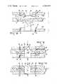
- FIG. 6is a section through the lines 6--6 of FIG. 3.
- FIG. 7is a section through the lines 7--7 of FIG. 3.
- FIG.8is a fragmentary sectional view of before application to a conductor.
- FIG. 9is a fragmentary sectional view during application to a conductor.
- FIG. 10is a fragmentary sectional view after application to a conductor.
- FIG. 11is a three dimensional view of a flat to round conductor connector according to the instant invention.
- FIG. 12is an illustration of the connector of FIG. 11 as applied to a three conductor cable.
- FIG. 13is an illustration of the butt splice of FIG. 2A as applied to a three conductor cable.
- FIG. 14is an illustration of the tap splice of FIG. 1 as applied to a three conductor cable.
- Cable 2has a flat conductor 4 with a thickness of approximately 0.009 in. (0.2286 mm) and two layers of insulation 6 of approximately 0.006 in. (0.1524mm) thick Mylar.
- the presently preferred material for use in the fabrication of terminal 10is 0.016 in. (0.4064mm) thick quarter hard brass.
- FIGS. 2A and 2Billustrate a butt splice and butt splice-tap respectively; however, it is obvious that other configurations are possible.
- the connector 10has a web 12 which electrically connects and is integral with the termination means 14.
- Termination means 14has a first plate which has four contact rings 16 which surround sawtooth lances 18 and a second plate which has four contact rings 16 which surround counterbores 20.
- Centerholes or pilot holes 22are located at the intersection of centerlines through contact rings 16 and on centerlines with each other. Centerholes 22 serve as manufacturing aides to assure centerline positioning among the plurality of contact rings.
- contact ring 16is formed by coining the material of termination means 14 upward to form a ridge.
- Edge 22 of contact ring 16has a maximum flat of 0.002 in. (0.0508mm) and a height of approximately 0.008 in. (0.2032mm) above flat 38.
- Surfaces 24are sloped from edge 22 at an angle of 60°.
- Coining void 26is approximately 0.009 in. (0.2286mm) wide and 0.021 in. (0.5334mm) deep; surface 28 has an 48° angle as measured from tip 30.
- Counterbore 20is formed by prepunching the material of terminating means 14 upward with a tapered punch to form taper 32 and then counterboring downward to obtain counterbore 20 with flat 34 being sharp to approximately 0.002 in. (0.0508mm). Ridge 36 is formed at the union of counterbore 20 and taper 32.
- contact ring 16is formed as previously described.
- Sawtooth lance 18is stamped and formed from the material of termnation means 14, with a width approximately equal to a diameter across flat 34 of counterbore 20 and a height of approximately 0.052 in. (1.3208mm) above flat 38. Tips 40 are located approximately 0.010 in. (0.254mm) in from the edges of the lance 18.
- termination means 14is folded back on itself to approximately a 20° angle to generally align counterbores 20 over sawtooth lances 18.
- a ribbon conductoris located in the fold of termination means 14 as shown in FIG. 8.
- Termination means 14is then pressed together with suitable flat surfaced tooling such as a simple handpress.
- the sawtooth lance 18will locate in counterbore 20 and establish precise alignment of opposing contact rings 16.
- the flat 34is in interference contact with the outer edge of lance 18.
- contact ring 16pierces the insulation over conductor and establishes an interference electrical contact therewith.
- Termination means 14is compressed to a total connection height of approximately 0.055 in. (1.397mm).
- Sawtooth lance 18is of sufficient height to penetrate through the stacked height of the connector material and cable and provide sufficient material for deformation as a mechanical locking means for the connector.
- FIG. 10shows a completed termination. Given a 0.009 in (0.2286mm) conductor 4 with insulation 6 of 0.006 in. (0.1524mm) on either side thereof it can be seen that the termination of the instant invention increases the height of the connection only by the thickness of the material used to fabricate termination means 14. It should also be recognized that contact rings 16 will sever the insulation 6 and embed themselves into the conductor approximately 0.002 in. (0.0508mm) on either side thereof, hence the conductor will not be served as electrical termination is achieved.
- the termination shown in FIG. 10is then bandaged with Mylar or other suitable insulation and waterproofing.
- FIG. 11illustrates a transition connection 40 for interconnecting flat and round conductors.
- Flat conductor termination means 14is a previously described hereinabove.
- Round conductor termination means 42is a preinsulated-insulation piercing barrel connector which in the preferred embodiment incorporates means to prevent overinsertion of the conductor in the wire barrel.
- a suitable round conductor terminating means 42is disclosed in U.S. Pat. No. 3,605,077.
Landscapes
- Multi-Conductor Connections (AREA)
- Coupling Device And Connection With Printed Circuit (AREA)
- Connections By Means Of Piercing Elements, Nuts, Or Screws (AREA)
Abstract
Description
1. Field of the Invention
The present invention is for use with flat conductor cable which generally comprises a tape-like strip of suitable insulation in which there are embedded a plurality fo ribbon-like conductors extending parallel to each other. Conductor cable of this type has been widely available for some years although conventional terminating and crimping techniques as are commonly applied to round wires are not applicable to this type of cable. As a result, a wide variety of specialized types of connecting devices has been developed for flat conductor cable. This invention lies in the broad field of flat conductor cable connectors.
2. Description of the Prior Art
The prior art shows a number of connectors for flat conductor cables; however, the prior art devices generally are unsatisfactory due to their height of termination, multiple parts and/or special tooling required for termination. The present invention solves the prior art problems by providing a minimum termination profile and simplified termination.
In accordance with a preferred embodiment of the invention, the connector has a plurality of contact rings located on opposed surfaces for establishing electrical contact with a flat conductor. One surface of said connector has a plurality of guide holes located within the contact rings and the other surface has a plurality of lance means located within the contact rings. The lances pierce the flat conductor and pass through the guide holes of the opposing surface. A simple press means is utilized to deform the lances behind the guide holes and establish a mechanical connection to secure the electrical termination.
It is an object of this invention to provide a minimum profile connector for flat conductors.
It is an object of this invention to provide a mimimum profile connector for flat conductors which is independent of the spring quality of the material used to fabricate the connector.
It is an object of this invention to provide a connector for making the transition from a flat conductor to a round conductor.
It is an object of this invention to provide a connector which is easily manufactured.
It is an object of this invention to provide a connector having a minimum profile which is compatible with the space occupied by conductor in a flat conductor cable.
FIG. 1 is a three dimensional view of a tap splice connector before application to a cable.
FIG. 2A is a three dimensional view of a butt splice connector before application to the cables.
FIG. 2B is a three dimensional view of a combination butt-tap splice connector.
FIG. 3 is a plan view of a butt splice connector before folding.
FIG. 4 is a three dimensional view of the contact ring and guide hole fragmented from a connector according to the instant invention.
FIG. 5 is a three dimensional view of the contact ring and lance fragmented from a connector according to the instant invention.
FIG. 6 is a section through thelines 6--6 of FIG. 3.
FIG. 7 is a section through thelines 7--7 of FIG. 3.
FIG.8 is a fragmentary sectional view of before application to a conductor.
FIG. 9 is a fragmentary sectional view during application to a conductor.
FIG. 10 is a fragmentary sectional view after application to a conductor.
FIG. 11 is a three dimensional view of a flat to round conductor connector according to the instant invention.
FIG. 12 is an illustration of the connector of FIG. 11 as applied to a three conductor cable.
FIG. 13 is an illustration of the butt splice of FIG. 2A as applied to a three conductor cable.
FIG. 14 is an illustration of the tap splice of FIG. 1 as applied to a three conductor cable.
Referring to FIG. 1, there is shown a 90°tap connector 10 according to the instant invention with thecables 2 exploded out.Cable 2 has aflat conductor 4 with a thickness of approximately 0.009 in. (0.2286 mm) and two layers ofinsulation 6 of approximately 0.006 in. (0.1524mm) thick Mylar. The presently preferred material for use in the fabrication ofterminal 10 is 0.016 in. (0.4064mm) thick quarter hard brass.
FIGS. 2A and 2B illustrate a butt splice and butt splice-tap respectively; however, it is obvious that other configurations are possible.
Referring now to FIG. 3, theconnector 10 has aweb 12 which electrically connects and is integral with the termination means 14. Termination means 14 has a first plate which has fourcontact rings 16 which surroundsawtooth lances 18 and a second plate which has fourcontact rings 16 which surroundcounterbores 20. Centerholes orpilot holes 22 are located at the intersection of centerlines throughcontact rings 16 and on centerlines with each other. Centerholes 22 serve as manufacturing aides to assure centerline positioning among the plurality of contact rings.
Referring now to FIGS. 4 and 5, there is shown respectively asingle contact ring 16 surroundingcounterbore 20 and lance 18. Referring to FIG. 6,contact ring 16 is formed by coining the material of termination means 14 upward to form a ridge.Edge 22 ofcontact ring 16 has a maximum flat of 0.002 in. (0.0508mm) and a height of approximately 0.008 in. (0.2032mm) aboveflat 38.Surfaces 24 are sloped fromedge 22 at an angle of 60°. Coiningvoid 26 is approximately 0.009 in. (0.2286mm) wide and 0.021 in. (0.5334mm) deep;surface 28 has an 48° angle as measured fromtip 30.
Referring now to FIGS. 5 and 7,contact ring 16 is formed as previously described.Sawtooth lance 18 is stamped and formed from the material of termnation means 14, with a width approximately equal to a diameter across flat 34 ofcounterbore 20 and a height of approximately 0.052 in. (1.3208mm) above flat 38.Tips 40 are located approximately 0.010 in. (0.254mm) in from the edges of thelance 18.
Referring again to FIG. 1, it can be seen that in practice the termination means 14 is folded back on itself to approximately a 20° angle to generally aligncounterbores 20 over sawtooth lances 18. In use a ribbon conductor is located in the fold of termination means 14 as shown in FIG. 8. Termination means 14 is then pressed together with suitable flat surfaced tooling such as a simple handpress. As shown in FIG. 9, thesawtooth lance 18 will locate incounterbore 20 and establish precise alignment of opposing contact rings 16. Notice that the flat 34 is in interference contact with the outer edge oflance 18. As termination means 14 is compressedlance 18 becomes deformed behindridge 36,contact ring 16 pierces the insulation over conductor and establishes an interference electrical contact therewith. Termination means 14 is compressed to a total connection height of approximately 0.055 in. (1.397mm).Sawtooth lance 18 is of sufficient height to penetrate through the stacked height of the connector material and cable and provide sufficient material for deformation as a mechanical locking means for the connector.
FIG. 10 shows a completed termination. Given a 0.009 in (0.2286mm)conductor 4 withinsulation 6 of 0.006 in. (0.1524mm) on either side thereof it can be seen that the termination of the instant invention increases the height of the connection only by the thickness of the material used to fabricate termination means 14. It should also be recognized that contact rings 16 will sever theinsulation 6 and embed themselves into the conductor approximately 0.002 in. (0.0508mm) on either side thereof, hence the conductor will not be served as electrical termination is achieved.
The termination shown in FIG. 10 is then bandaged with Mylar or other suitable insulation and waterproofing.
FIG. 11 illustrates atransition connection 40 for interconnecting flat and round conductors. Flat conductor termination means 14 is a previously described hereinabove. Round conductor termination means 42 is a preinsulated-insulation piercing barrel connector which in the preferred embodiment incorporates means to prevent overinsertion of the conductor in the wire barrel. A suitable round conductor terminating means 42 is disclosed in U.S. Pat. No. 3,605,077.
Although preferred embodiments of the present invention are disclosed and shown in detail, other modifications and embodiments which would be apparent to one having ordinary skill in the art, are intended to be covered by the spirit and scope of the claims.
Claims (10)
1. An electrical connector comprising:
first and second electrically connected termination means,
said first and second termination means being comprised of first and second opposed surfaces,
said first opposed surface having a plurality of contact rings thereon and a guide hole located within each of said plurality of contact rings,
said second opposed surface having a plurality of contact rings, equal to said plurality of contact rings on said first opposed surface, thereon and a lance means located within each of said plurality of contact rings, whereby upon moving said opposed surfaces together, said lances pass through said guide holes and said plurality of contact rings on said first surfaces are in alignment with said plurality of contact rings on said second surface.
2. A stamped and formed electrical connector comprising:
first and second termination means electrically connected by an integral web,
said first and second termination means further comprising first and second opposed surfaces having a pilot hole on centerline with each other,
said first opposed surface having a plurality of contact rings radiated about said pilot hole and a pluraity of guide holes radiated about said pilot hole,
said second opposed surface having a plurality of contact rings, equal in number to said contact rings on said first surface, radiated about said pilot hole, at a distance equal to said contact rings on said first surface, and a plurality of lance means equal in number to and on center with said plurality of guide holes in said first opposed surface.
3. A stamped and formed electrical connector according to claim 3 wherein:
said plurality of guide holes in said first opposed surface are equal in number to said contact rings thereon and are centered within said contact rings, and
said plurality of lance means on said second opposed surface are equal in number to said guide holes and are centered within said contact rings on said second surface.
4. A connector for electrical connection to a flat conductor, comprising:
one or more pairs of flat metal plates, with said plates of each pair integrally joined along a fold,
each of said plates having one or more ridges projecting outwardly toward and in alignment with respective said one or more ridges of the other plate of the same pair,
a first plate of each said pair being provided with one or more lances bent out of the thickness of said first plate and projecting toward a respective second plate of the same pair,
said second plate of each said pair being provided with one or more apertures, each of a diameter less than the width of a respective one of said lances, and each being encircled by a lip projecting outwardly toward a respective said first plate of the same pair,
each said pair of plates being constructed for being folded against opposite surfaces of a respective, insulation covered, flat conductor, with said ridges of said pair of plates penetrating through said insulation and penetrating partially into said flat conductor for establishing a completed electrical connection therewith, and
with each said lance projecting through said flat conductor and wedgingly retaining in a respective aperture, lockingly retaining a respective said pair of plates against said flat conductor, and aligning said ridges on a respective pair of plates directly opposite one another across the thickness of said flat conductor.
5. The structure as recited in claim 4, wherein, the height of said completed electrical connection is the sum of thicknesses of said metal plates and said insulation covered flat conductor.
6. The structure as recited in claim 4, wherein, each said lance is bounded by a respective said ridge of a respective said first plate, and each said aperture is bounded by a respective said ridge of a respective said second plate.
7. The structure as recited in claim 4, wherein, at least one of said metal plates of each said pair is provided with means projecting outwardly of said pair when folded against said flat conductor for electrically connecting to an electrical wire.
8. The structure as recited in claim 4, wherein, each said first plate includes a first pilot hole therethrough precisely spaced from each said lance, and
each said second plate includes a second pilot hole therethrough precisely spaced from each said aperture.
9. The structure as recited in claim 8, wherein, each said first pilot hole is equidistant from each said lances provided on the same said first plate, and each said second pilot hole is equidistant from each said apertures provided through the same said second plate.
10. The structure as recited in claim 6, wherein, each said lip provides a tapered counterbore for a respective said aperture, and each said lance free end thereof is of reduced width to enter a respective said tapered counterbore.
Priority Applications (8)
| Application Number | Priority Date | Filing Date | Title |
|---|---|---|---|
| US06/043,966US4263474A (en) | 1979-05-30 | 1979-05-30 | Under carpet cable connector |
| EP80301447AEP0020031B1 (en) | 1979-05-30 | 1980-05-02 | Electrical connector for flat cable |
| DE8080301447TDE3062111D1 (en) | 1979-05-30 | 1980-05-02 | Electrical connector for flat cable |
| CA351,692ACA1125400A (en) | 1979-05-30 | 1980-05-12 | Electrical connector |
| BR8003302ABR8003302A (en) | 1979-05-30 | 1980-05-27 | ELECTRICAL CONNECTOR TO END A FLAT CABLE |
| JP7214480AJPS55161382A (en) | 1979-05-30 | 1980-05-29 | Electric connector for flat cable |
| ES1980251045UES251045Y (en) | 1979-05-30 | 1980-05-29 | AN ELECTRICAL CONNECTOR |
| HK31/87AHK3187A (en) | 1979-05-30 | 1987-01-08 | Electrical connector for flat cable |
Applications Claiming Priority (1)
| Application Number | Priority Date | Filing Date | Title |
|---|---|---|---|
| US06/043,966US4263474A (en) | 1979-05-30 | 1979-05-30 | Under carpet cable connector |
Publications (1)
| Publication Number | Publication Date |
|---|---|
| US4263474Atrue US4263474A (en) | 1981-04-21 |
Family
ID=21929842
Family Applications (1)
| Application Number | Title | Priority Date | Filing Date |
|---|---|---|---|
| US06/043,966Expired - LifetimeUS4263474A (en) | 1979-05-30 | 1979-05-30 | Under carpet cable connector |
Country Status (8)
| Country | Link |
|---|---|
| US (1) | US4263474A (en) |
| EP (1) | EP0020031B1 (en) |
| JP (1) | JPS55161382A (en) |
| BR (1) | BR8003302A (en) |
| CA (1) | CA1125400A (en) |
| DE (1) | DE3062111D1 (en) |
| ES (1) | ES251045Y (en) |
| HK (1) | HK3187A (en) |
Cited By (43)
| Publication number | Priority date | Publication date | Assignee | Title |
|---|---|---|---|---|
| US4417096A (en)* | 1981-01-26 | 1983-11-22 | Amp Incorporated | Method for splicing a flat conductor cable enclosed within a sealed envelope |
| US4433890A (en) | 1981-07-06 | 1984-02-28 | Marino Vincent E | Connectors for flexible printed circuits and method therefor |
| US4446330A (en)* | 1981-10-26 | 1984-05-01 | Burndy Corporation | Electrical service module with strain relief member |
| US4490904A (en)* | 1982-05-03 | 1985-01-01 | Burndy Corporation | Apparatus and method for installing electrical connectors on flat conductor cable |
| US4498715A (en)* | 1983-03-29 | 1985-02-12 | Amp Incorporated | Cable shield grounding clamp |
| US4543716A (en)* | 1983-09-23 | 1985-10-01 | The Wiremold Company | Method and apparatus for electrical connection of flat cables |
| US4560224A (en)* | 1982-01-15 | 1985-12-24 | Amp Incorporated | Flat cable termination |
| US4560225A (en)* | 1983-05-24 | 1985-12-24 | Servocavi S.P.A. | Electrical connector for flat cables and assembly thereof with a flat cable |
| US4571019A (en)* | 1981-12-17 | 1986-02-18 | Mitsubishi Denki Kabushiki Kaisha | Connecting terminal |
| US4630362A (en)* | 1981-10-26 | 1986-12-23 | Burndy Corporation | Apparatus for installing electrical on flat conductor cable |
| US4676850A (en)* | 1985-08-19 | 1987-06-30 | Thomas & Betts Corporation | Method of making an electrical cable for undercarpet wiring systems |
| US4695679A (en)* | 1985-08-19 | 1987-09-22 | Thomas & Betts Corporation | Flat multiconductor cable for undercarpet wiring system |
| US4783579A (en)* | 1986-04-29 | 1988-11-08 | Amp Incorporated | Flat multi-conductor power cable with two insulating layers |
| US4806121A (en)* | 1986-07-11 | 1989-02-21 | N.E.D. Nicomatic Electronic Department | Contact socket element, strip comprising it and its manufacturing |
| US4821409A (en)* | 1981-10-26 | 1989-04-18 | Burndy Corporation | Electrical connection apparatus for flat conductor cables and similar articles |
| US4834673A (en)* | 1987-05-14 | 1989-05-30 | Amp Incorporated | Flat cable power distribution system |
| US4963699A (en)* | 1988-04-12 | 1990-10-16 | Sumitomo Electric Industries, Ltd. | Apparatus for connecting sets of electric wires to lead wires |
| US4975080A (en)* | 1988-05-13 | 1990-12-04 | Amp Incorporated | Locking means for electrical interconnecting structures |
| US5242313A (en)* | 1989-02-21 | 1993-09-07 | Amphenol Socapex | Connection assembly between a common multiconductor bundle and a branched multiconductor bundle |
| EP0926764A3 (en)* | 1997-12-26 | 2000-08-30 | The Whitaker Corporation | Electrical contact for flexible flat cable |
| US6730848B1 (en)* | 2001-06-29 | 2004-05-04 | Antaya Technologies Corporation | Techniques for connecting a lead to a conductor |
| US20050178577A1 (en)* | 2004-02-12 | 2005-08-18 | Duesterhoeft Scott S. | Electrical contact and connector |
| DE202004012418U1 (en)* | 2004-08-06 | 2005-12-15 | Lear Corp., Southfield | Multi-layered electrical contact unit for flexible film conductors, has rivet contact comprising rivet head, and two dump irons at cavity, where irons stretch radially outward and are bent in obtuse angle in direction of rivet head |
| DE102009028618A1 (en)* | 2009-08-18 | 2011-02-24 | Telsonic Holding Ag | Gripping element for connection with a conductor such as cable or conductor rail surrounded by an electrically insulated plastic layer by friction welding, has a cutting tool-like structure for permeating the plastic layer, and thread bolt |
| US8353650B2 (en) | 2006-04-21 | 2013-01-15 | Hubbell Incorporated | Bonding washer |
| US8888431B2 (en) | 2013-03-15 | 2014-11-18 | Hubbell Incorporated | Adjustable bonding washer |
| US9065191B2 (en) | 2013-02-25 | 2015-06-23 | Hubbell Incorporated | Single fastener electrical connector |
| US9520657B2 (en) | 2014-07-31 | 2016-12-13 | Hubbell Incorporated | Electrical terminal |
| US20170141488A1 (en)* | 2014-06-19 | 2017-05-18 | Fujikura Ltd. | Crimp terminal |
| US11035126B2 (en) | 2011-02-25 | 2021-06-15 | Rmh Tech Llc | Mounting device for building surfaces having elongated mounting slot |
| US11041310B1 (en) | 2020-03-17 | 2021-06-22 | Rmh Tech Llc | Mounting device for controlling uplift of a metal roof |
| US11085188B2 (en)* | 2016-10-31 | 2021-08-10 | Rmh Tech Llc | Metal panel electrical bonding clip |
| US11333179B2 (en) | 2011-12-29 | 2022-05-17 | Rmh Tech Llc | Mounting device for nail strip panels |
| US11352793B2 (en) | 2020-03-16 | 2022-06-07 | Rmh Tech Llc | Mounting device for a metal roof |
| US20220263256A1 (en)* | 2019-07-18 | 2022-08-18 | Valeo Systemes Thermiques | Metal electrical connector for flexible electrically conductive strip and related conductive strip connector assembly |
| US11441596B2 (en) | 2018-10-29 | 2022-09-13 | Hubbell Incorporated | Bonding washer |
| US11573033B2 (en) | 2016-07-29 | 2023-02-07 | Rmh Tech Llc | Trapezoidal rib mounting bracket with flexible legs |
| US11616468B2 (en) | 2018-03-21 | 2023-03-28 | Rmh Tech Llc | PV module mounting assembly with clamp/standoff arrangement |
| US11668332B2 (en) | 2018-12-14 | 2023-06-06 | Rmh Tech Llc | Mounting device for nail strip panels |
| US11774143B2 (en) | 2017-10-09 | 2023-10-03 | Rmh Tech Llc | Rail assembly with invertible side-mount adapter for direct and indirect mounting applications |
| US12203496B2 (en) | 2020-07-09 | 2025-01-21 | Rmh Tech Llc | Mounting system, device, and method |
| USD1075493S1 (en) | 2022-07-06 | 2025-05-20 | Rmh Tech Llc | Clamp for a photovoltaic module mounting assembly |
| US12372107B2 (en) | 2019-12-30 | 2025-07-29 | Hubbell Incorporated | Bonding clips |
Families Citing this family (10)
| Publication number | Priority date | Publication date | Assignee | Title |
|---|---|---|---|---|
| ATE19151T1 (en)* | 1981-09-28 | 1986-04-15 | Ici Plc | ARRANGEMENT TO ELECTRIC FINISH. |
| JPS58155681A (en)* | 1982-03-10 | 1983-09-16 | 松下電工株式会社 | Connector |
| JPS58155680A (en)* | 1982-03-10 | 1983-09-16 | 松下電工株式会社 | Connector |
| JPS5957867U (en)* | 1982-10-08 | 1984-04-16 | 松下電工株式会社 | Flat cable connection structure |
| JPS5957866U (en)* | 1982-10-08 | 1984-04-16 | 松下電工株式会社 | Structure of flat cable connection |
| JPS5971273A (en)* | 1982-10-15 | 1984-04-21 | 松下電工株式会社 | Connector connecting flat wire |
| GB2192101A (en)* | 1986-06-30 | 1987-12-31 | Johnson Electric Ind Mfg | Insulation piercing crimp terminal |
| US4902245A (en)* | 1989-04-21 | 1990-02-20 | Amp Incorporated | Methods and apparatus for terminating and interconnecting flat power cables |
| JP2547712Y2 (en)* | 1991-02-27 | 1997-09-17 | 矢崎総業株式会社 | Flat cable branch connection device |
| JP2510603Y2 (en)* | 1991-03-06 | 1996-09-18 | 矢崎総業株式会社 | Flat cable branch terminal |
Citations (8)
| Publication number | Priority date | Publication date | Assignee | Title |
|---|---|---|---|---|
| US2020408A (en)* | 1935-11-12 | Condenser foil terminal | ||
| US2250280A (en)* | 1940-05-14 | 1941-07-22 | Maurice M Starbird | Electrical bond |
| US3138658A (en)* | 1961-09-27 | 1964-06-23 | Amp Inc | Electrical connector for very thin sheet metal member |
| US3247316A (en)* | 1964-04-22 | 1966-04-19 | Amp Inc | Electrical connector for terminating aluminum foil |
| US3541226A (en)* | 1968-12-02 | 1970-11-17 | Amp Inc | Electrical connector for terminating multilayer conductive foil and corrugated insulation therefor |
| US3541227A (en)* | 1968-11-13 | 1970-11-17 | Amp Inc | Terminal for interconnecting foil conductor and wire conductor |
| US3662089A (en)* | 1969-11-13 | 1972-05-09 | Post Office | Modifications of wire connectors |
| US3752901A (en)* | 1971-08-23 | 1973-08-14 | Thomas & Betts Corp | Foil connector |
Family Cites Families (2)
| Publication number | Priority date | Publication date | Assignee | Title |
|---|---|---|---|---|
| US3197729A (en)* | 1962-08-09 | 1965-07-27 | Burndy Corp | Semi-rivet connector |
| BE757965A (en)* | 1969-11-06 | 1971-04-23 | Amp Inc | ELECTRICAL CONNECTOR |
- 1979
- 1979-05-30USUS06/043,966patent/US4263474A/ennot_activeExpired - Lifetime
- 1980
- 1980-05-02DEDE8080301447Tpatent/DE3062111D1/ennot_activeExpired
- 1980-05-02EPEP80301447Apatent/EP0020031B1/ennot_activeExpired
- 1980-05-12CACA351,692Apatent/CA1125400A/ennot_activeExpired
- 1980-05-27BRBR8003302Apatent/BR8003302A/ennot_activeIP Right Cessation
- 1980-05-29JPJP7214480Apatent/JPS55161382A/enactiveGranted
- 1980-05-29ESES1980251045Upatent/ES251045Y/ennot_activeExpired
- 1987
- 1987-01-08HKHK31/87Apatent/HK3187A/enunknown
Patent Citations (8)
| Publication number | Priority date | Publication date | Assignee | Title |
|---|---|---|---|---|
| US2020408A (en)* | 1935-11-12 | Condenser foil terminal | ||
| US2250280A (en)* | 1940-05-14 | 1941-07-22 | Maurice M Starbird | Electrical bond |
| US3138658A (en)* | 1961-09-27 | 1964-06-23 | Amp Inc | Electrical connector for very thin sheet metal member |
| US3247316A (en)* | 1964-04-22 | 1966-04-19 | Amp Inc | Electrical connector for terminating aluminum foil |
| US3541227A (en)* | 1968-11-13 | 1970-11-17 | Amp Inc | Terminal for interconnecting foil conductor and wire conductor |
| US3541226A (en)* | 1968-12-02 | 1970-11-17 | Amp Inc | Electrical connector for terminating multilayer conductive foil and corrugated insulation therefor |
| US3662089A (en)* | 1969-11-13 | 1972-05-09 | Post Office | Modifications of wire connectors |
| US3752901A (en)* | 1971-08-23 | 1973-08-14 | Thomas & Betts Corp | Foil connector |
Cited By (72)
| Publication number | Priority date | Publication date | Assignee | Title |
|---|---|---|---|---|
| US4417096A (en)* | 1981-01-26 | 1983-11-22 | Amp Incorporated | Method for splicing a flat conductor cable enclosed within a sealed envelope |
| US4433890A (en) | 1981-07-06 | 1984-02-28 | Marino Vincent E | Connectors for flexible printed circuits and method therefor |
| US4821409A (en)* | 1981-10-26 | 1989-04-18 | Burndy Corporation | Electrical connection apparatus for flat conductor cables and similar articles |
| US4446330A (en)* | 1981-10-26 | 1984-05-01 | Burndy Corporation | Electrical service module with strain relief member |
| US4630362A (en)* | 1981-10-26 | 1986-12-23 | Burndy Corporation | Apparatus for installing electrical on flat conductor cable |
| US4571019A (en)* | 1981-12-17 | 1986-02-18 | Mitsubishi Denki Kabushiki Kaisha | Connecting terminal |
| US4560224A (en)* | 1982-01-15 | 1985-12-24 | Amp Incorporated | Flat cable termination |
| US4490904A (en)* | 1982-05-03 | 1985-01-01 | Burndy Corporation | Apparatus and method for installing electrical connectors on flat conductor cable |
| US4498715A (en)* | 1983-03-29 | 1985-02-12 | Amp Incorporated | Cable shield grounding clamp |
| US4560225A (en)* | 1983-05-24 | 1985-12-24 | Servocavi S.P.A. | Electrical connector for flat cables and assembly thereof with a flat cable |
| US4543716A (en)* | 1983-09-23 | 1985-10-01 | The Wiremold Company | Method and apparatus for electrical connection of flat cables |
| US4676850A (en)* | 1985-08-19 | 1987-06-30 | Thomas & Betts Corporation | Method of making an electrical cable for undercarpet wiring systems |
| US4695679A (en)* | 1985-08-19 | 1987-09-22 | Thomas & Betts Corporation | Flat multiconductor cable for undercarpet wiring system |
| US4783579A (en)* | 1986-04-29 | 1988-11-08 | Amp Incorporated | Flat multi-conductor power cable with two insulating layers |
| US4806121A (en)* | 1986-07-11 | 1989-02-21 | N.E.D. Nicomatic Electronic Department | Contact socket element, strip comprising it and its manufacturing |
| US4834673A (en)* | 1987-05-14 | 1989-05-30 | Amp Incorporated | Flat cable power distribution system |
| US4963699A (en)* | 1988-04-12 | 1990-10-16 | Sumitomo Electric Industries, Ltd. | Apparatus for connecting sets of electric wires to lead wires |
| US4975080A (en)* | 1988-05-13 | 1990-12-04 | Amp Incorporated | Locking means for electrical interconnecting structures |
| US5242313A (en)* | 1989-02-21 | 1993-09-07 | Amphenol Socapex | Connection assembly between a common multiconductor bundle and a branched multiconductor bundle |
| EP0926764A3 (en)* | 1997-12-26 | 2000-08-30 | The Whitaker Corporation | Electrical contact for flexible flat cable |
| US6730848B1 (en)* | 2001-06-29 | 2004-05-04 | Antaya Technologies Corporation | Techniques for connecting a lead to a conductor |
| US20040158981A1 (en)* | 2001-06-29 | 2004-08-19 | Antaya Technologies Corporation | Techniques for connecting a lead to a conductor |
| US20050178577A1 (en)* | 2004-02-12 | 2005-08-18 | Duesterhoeft Scott S. | Electrical contact and connector |
| US6933445B1 (en)* | 2004-02-12 | 2005-08-23 | Tyco Electronics Corporation | Electrical contact and connector |
| DE202004012418U1 (en)* | 2004-08-06 | 2005-12-15 | Lear Corp., Southfield | Multi-layered electrical contact unit for flexible film conductors, has rivet contact comprising rivet head, and two dump irons at cavity, where irons stretch radially outward and are bent in obtuse angle in direction of rivet head |
| US9074616B2 (en) | 2006-04-21 | 2015-07-07 | Hubbell Incorporated | Bonding washer |
| US9447813B2 (en) | 2006-04-21 | 2016-09-20 | Hubbell Incorporated | Bonding washer |
| US8353650B2 (en) | 2006-04-21 | 2013-01-15 | Hubbell Incorporated | Bonding washer |
| US8608418B2 (en) | 2006-04-21 | 2013-12-17 | Hubbell Incorporated | Bonding washer |
| US11542978B2 (en) | 2006-04-21 | 2023-01-03 | Hubbell Incorporated | Bonding washer |
| US10036414B2 (en) | 2006-04-21 | 2018-07-31 | Hubbell Incorporated | Bonding washer |
| US10180158B2 (en) | 2006-04-21 | 2019-01-15 | Hubbell Incorporated | Bonding washer |
| US10655668B2 (en) | 2006-04-21 | 2020-05-19 | Hubbell Incorporated | Bonding washer |
| US10823221B2 (en) | 2006-04-21 | 2020-11-03 | Hubbell Incorporated | Bonding washer |
| US9500220B2 (en) | 2006-04-21 | 2016-11-22 | Hubbell Incorporated | Bonding washer |
| DE102009028618A1 (en)* | 2009-08-18 | 2011-02-24 | Telsonic Holding Ag | Gripping element for connection with a conductor such as cable or conductor rail surrounded by an electrically insulated plastic layer by friction welding, has a cutting tool-like structure for permeating the plastic layer, and thread bolt |
| DE102009028618B4 (en)* | 2009-08-18 | 2011-07-28 | Telsonic Holding Ag | Method of making an electrical tap on an insulated conductor |
| US11035126B2 (en) | 2011-02-25 | 2021-06-15 | Rmh Tech Llc | Mounting device for building surfaces having elongated mounting slot |
| US11885139B2 (en) | 2011-02-25 | 2024-01-30 | Rmh Tech Llc | Mounting device for building surfaces having elongated mounting slot |
| US12018861B2 (en) | 2011-12-29 | 2024-06-25 | Rmh Tech Llc | Mounting device for nail strip panels |
| US11333179B2 (en) | 2011-12-29 | 2022-05-17 | Rmh Tech Llc | Mounting device for nail strip panels |
| US9472864B2 (en) | 2013-02-25 | 2016-10-18 | Hubbell Incorporated | Single fastener electrical connector |
| US9853370B2 (en) | 2013-02-25 | 2017-12-26 | Hubbell Incorporated | Single fastener electrical connector |
| US9065191B2 (en) | 2013-02-25 | 2015-06-23 | Hubbell Incorporated | Single fastener electrical connector |
| US9595772B2 (en) | 2013-03-15 | 2017-03-14 | Hubbell Incorporated | Adjustable bonding washer |
| US8888431B2 (en) | 2013-03-15 | 2014-11-18 | Hubbell Incorporated | Adjustable bonding washer |
| US20170141488A1 (en)* | 2014-06-19 | 2017-05-18 | Fujikura Ltd. | Crimp terminal |
| US10128581B2 (en)* | 2014-06-19 | 2018-11-13 | Fujikura Ltd. | Crimp terminal |
| US9520657B2 (en) | 2014-07-31 | 2016-12-13 | Hubbell Incorporated | Electrical terminal |
| US12044443B2 (en) | 2016-07-29 | 2024-07-23 | Rmh Tech Llc | Trapezoidal rib mounting bracket with flexible legs |
| US11573033B2 (en) | 2016-07-29 | 2023-02-07 | Rmh Tech Llc | Trapezoidal rib mounting bracket with flexible legs |
| US11085188B2 (en)* | 2016-10-31 | 2021-08-10 | Rmh Tech Llc | Metal panel electrical bonding clip |
| US11808043B2 (en)* | 2016-10-31 | 2023-11-07 | Rmh Tech Llc | Metal panel electrical bonding clip |
| US20210363755A1 (en)* | 2016-10-31 | 2021-11-25 | Rmh Tech Llc | Metal panel electrical bonding clip |
| US11774143B2 (en) | 2017-10-09 | 2023-10-03 | Rmh Tech Llc | Rail assembly with invertible side-mount adapter for direct and indirect mounting applications |
| US12231081B2 (en) | 2018-03-21 | 2025-02-18 | Rmh Tech Llc | PV module mounting assembly with clamp/standoff arrangement |
| US11616468B2 (en) | 2018-03-21 | 2023-03-28 | Rmh Tech Llc | PV module mounting assembly with clamp/standoff arrangement |
| US11441596B2 (en) | 2018-10-29 | 2022-09-13 | Hubbell Incorporated | Bonding washer |
| US11976682B2 (en) | 2018-10-29 | 2024-05-07 | Hubbell Incorporated | Bonding washer |
| US11668332B2 (en) | 2018-12-14 | 2023-06-06 | Rmh Tech Llc | Mounting device for nail strip panels |
| US12320375B2 (en) | 2018-12-14 | 2025-06-03 | Rmh Tech Llc | Mounting device for nail strip panels |
| US20220263256A1 (en)* | 2019-07-18 | 2022-08-18 | Valeo Systemes Thermiques | Metal electrical connector for flexible electrically conductive strip and related conductive strip connector assembly |
| US12372107B2 (en) | 2019-12-30 | 2025-07-29 | Hubbell Incorporated | Bonding clips |
| US11739529B2 (en) | 2020-03-16 | 2023-08-29 | Rmh Tech Llc | Mounting device for a metal roof |
| US11965337B2 (en) | 2020-03-16 | 2024-04-23 | Rmh Tech Llc | Mounting device for a metal roof |
| US12305397B2 (en) | 2020-03-16 | 2025-05-20 | Rmh Tech Llc | Mounting device for a metal roof |
| US11512474B2 (en) | 2020-03-16 | 2022-11-29 | Rmh Tech Llc | Mounting device for a metal roof |
| US11352793B2 (en) | 2020-03-16 | 2022-06-07 | Rmh Tech Llc | Mounting device for a metal roof |
| US11041310B1 (en) | 2020-03-17 | 2021-06-22 | Rmh Tech Llc | Mounting device for controlling uplift of a metal roof |
| US11788291B2 (en) | 2020-03-17 | 2023-10-17 | Rmh Tech Llc | Mounting device for controlling uplift of a metal roof |
| US12203496B2 (en) | 2020-07-09 | 2025-01-21 | Rmh Tech Llc | Mounting system, device, and method |
| USD1075493S1 (en) | 2022-07-06 | 2025-05-20 | Rmh Tech Llc | Clamp for a photovoltaic module mounting assembly |
Also Published As
| Publication number | Publication date |
|---|---|
| JPS55161382A (en) | 1980-12-15 |
| CA1125400A (en) | 1982-06-08 |
| BR8003302A (en) | 1980-12-30 |
| JPS6258112B2 (en) | 1987-12-04 |
| EP0020031A3 (en) | 1981-02-04 |
| EP0020031B1 (en) | 1983-02-23 |
| ES251045Y (en) | 1981-05-16 |
| DE3062111D1 (en) | 1983-03-31 |
| HK3187A (en) | 1987-01-16 |
| EP0020031A2 (en) | 1980-12-10 |
| ES251045U (en) | 1980-12-01 |
Similar Documents
| Publication | Publication Date | Title |
|---|---|---|
| US4263474A (en) | Under carpet cable connector | |
| JP2993644B2 (en) | Flat cable connector | |
| US4261629A (en) | Slotted plate terminal | |
| US6394833B1 (en) | Flat flexible cable connector | |
| US4240687A (en) | Transition block for terminating flat conductors | |
| US4775337A (en) | Conductive wire with integral electrical terminal | |
| US3395381A (en) | Crimpable connecting device for flat conductor cable | |
| US4040702A (en) | Solderless termination system | |
| US3881796A (en) | Terminal for flat conductor | |
| CA1039374A (en) | Method and apparatus for flat conductor cable termination | |
| US4836803A (en) | Wire holding device in an electrical connector | |
| JPS5824908B2 (en) | electrical connectors | |
| JPS6051789B2 (en) | electrical terminals | |
| JPS5936386B2 (en) | electrical terminals | |
| US5078617A (en) | Piercing insulation displacement board terminal | |
| US4113338A (en) | Insulation-piercing contact | |
| GB2076601A (en) | Assembly method for flat cable connector | |
| US4573752A (en) | Flat cable connection system | |
| US4373769A (en) | Electrical connector including insulation-opening contact | |
| US3243757A (en) | Electrical connections | |
| JPH05144484A (en) | Insulation rejecting type probe and connector using this probe | |
| US3768062A (en) | Terminal for flexible circuits | |
| US4125311A (en) | Insulation-piercing contact member and connector | |
| US20080242139A1 (en) | Connector and Line Connecting Method Thereof | |
| US4600259A (en) | Electrical terminal having wire-receiving slot for relatively small diameter wires and connectors containing such terminals |
Legal Events
| Date | Code | Title | Description |
|---|---|---|---|
| STCF | Information on status: patent grant | Free format text:PATENTED CASE |